EP0442038A2 - Method and device for automatically replacing a full roll by a new winding core - Google Patents
Method and device for automatically replacing a full roll by a new winding core Download PDFInfo
- Publication number
- EP0442038A2 EP0442038A2 EP90119865A EP90119865A EP0442038A2 EP 0442038 A2 EP0442038 A2 EP 0442038A2 EP 90119865 A EP90119865 A EP 90119865A EP 90119865 A EP90119865 A EP 90119865A EP 0442038 A2 EP0442038 A2 EP 0442038A2
- Authority
- EP
- European Patent Office
- Prior art keywords
- web
- roller
- winding
- support
- roll
- Prior art date
- Legal status (The legal status is an assumption and is not a legal conclusion. Google has not performed a legal analysis and makes no representation as to the accuracy of the status listed.)
- Granted
Links
- 238000004804 winding Methods 0.000 title claims abstract description 73
- 238000000034 method Methods 0.000 title claims description 17
- 239000000463 material Substances 0.000 claims abstract description 14
- 239000000853 adhesive Substances 0.000 claims abstract description 7
- 230000001070 adhesive effect Effects 0.000 claims abstract description 7
- 230000003313 weakening effect Effects 0.000 claims abstract description 5
- 239000002390 adhesive tape Substances 0.000 claims description 18
- 238000003780 insertion Methods 0.000 abstract description 6
- 230000037431 insertion Effects 0.000 abstract description 6
- 230000000717 retained effect Effects 0.000 abstract description 2
- 239000000123 paper Substances 0.000 description 13
- 239000011111 cardboard Substances 0.000 description 4
- 239000011087 paperboard Substances 0.000 description 4
- 239000003292 glue Substances 0.000 description 2
- 238000000926 separation method Methods 0.000 description 2
- 238000010276 construction Methods 0.000 description 1
Images
Classifications
-
- B—PERFORMING OPERATIONS; TRANSPORTING
- B65—CONVEYING; PACKING; STORING; HANDLING THIN OR FILAMENTARY MATERIAL
- B65H—HANDLING THIN OR FILAMENTARY MATERIAL, e.g. SHEETS, WEBS, CABLES
- B65H19/00—Changing the web roll
- B65H19/22—Changing the web roll in winding mechanisms or in connection with winding operations
- B65H19/2238—The web roll being driven by a winding mechanism of the nip or tangential drive type
- B65H19/2246—The web roll being driven by a winding mechanism of the nip or tangential drive type and the roll being supported on two rollers
-
- B—PERFORMING OPERATIONS; TRANSPORTING
- B65—CONVEYING; PACKING; STORING; HANDLING THIN OR FILAMENTARY MATERIAL
- B65H—HANDLING THIN OR FILAMENTARY MATERIAL, e.g. SHEETS, WEBS, CABLES
- B65H19/00—Changing the web roll
- B65H19/22—Changing the web roll in winding mechanisms or in connection with winding operations
- B65H19/28—Attaching the leading end of the web to the replacement web-roll core or spindle
- B65H19/286—Attaching the leading end of the web to the replacement web-roll core or spindle by applying adhesive to the web
-
- B—PERFORMING OPERATIONS; TRANSPORTING
- B65—CONVEYING; PACKING; STORING; HANDLING THIN OR FILAMENTARY MATERIAL
- B65H—HANDLING THIN OR FILAMENTARY MATERIAL, e.g. SHEETS, WEBS, CABLES
- B65H2301/00—Handling processes for sheets or webs
- B65H2301/40—Type of handling process
- B65H2301/41—Winding, unwinding
- B65H2301/417—Handling or changing web rolls
- B65H2301/418—Changing web roll
- B65H2301/4182—Core or mandrel insertion, e.g. means for loading core or mandrel in winding position
- B65H2301/41826—Core or mandrel insertion, e.g. means for loading core or mandrel in winding position by gripping or pushing means, mechanical or suction gripper
Definitions
- the invention relates to a method for automatically changing a full winding roll against a new winding tube in support roller winding machines and a support roller winding machine for carrying out the method.
- a device On support roller winding machines for heavier types of paper, a device is known from DE-OS 31 51 256 which consists of a structural unit which can be pivoted about the axis of one of the support rollers by means of pivoting levers and comprises a stapling and cutting device.
- the cutting device is an active knife that can be moved across the web width and cuts the web on the winding tube, with the newly formed beginning of the web being stapled or glued to the winding tube.
- the device for cutting and tacking the web is very complex in construction and takes a relatively long time.
- DE-OS 36 11 895 describes a generic method in a back-up roll winding machine in which the web of material is first weakened before reaching the back-up roll, a trace of glue is applied to both sides of the weakening and the web is separated by braking on the back-up roll.
- the web ends stick to the surface due to the negative pressure prevailing in the support roller until they have reached the winding roll and stick to it.
- the newly created web beginnings remain braked during this movement, so that the support roller spins under the suctioned web start until the unloaded finished rolls and release of the brake, the glued web start is transported from the support roller to the sleeves and glued.
- the invention has for its object to improve a generic method so that it can be used in support roller winding machines even when winding heavy paper (greater than 120 g / m2) for the fastest and most reliable roll change.
- claim 2 contains a particularly advantageous variant of a method according to claim 1, claims 3 to 5 support roller winding machines for carrying out a method according to the invention are claimed.
- the particularly advantageous embodiment according to claim 5 enables the processing of paper or cardboard webs of the entire basis weight range with very little downtime for a roll change.
- the carrier roller winding machine has two driven carrier rollers 1, 2, between which a roller bed 3 is formed, in which the winding rollers 4 rest on the carrier rollers 1, 2 during winding.
- Such double carrier roll winding machines are widely known and z. B. described in DE-OS 32 07 461, so that individual parts, insofar as they do not relate to the invention, are not dealt with.
- the wrapped support roller 1 is designed as a suction roller, it can be subjected to a vacuum to hold the web 5.
- a machine-wide support 6 which can be raised and lowered and which, at its upper end, carries a separating knife 7 which can be folded in the direction of the support roller 1 and extends over the entire working width and which thus passes through the gap between the Carrier rollers 1, 2 moved into the upper gusset between the two carrier rollers 1, 2 (roller bed 3) and at the same time can be lowered into a position that does not interfere with the winding.
- rollers 8 are freely rotating and resiliently mounted on the support 6 over the working width in such a way that they abut the circumference of the supporting roller 1 in a position slightly above the narrowest point between the two supporting rollers 1, 2.
- a perforating device 10 and two adhesive tape dispensers 11, 12 are arranged on the inlet side, just before the web 5 touches the support roller 1.
- the perforating device 10 consists of a toothed knife which extends over the working width and which can be moved into the groove of a counter-holder 13 arranged on the other side of the web.
- the counter-holder 13 has, in addition to the groove, support surfaces for the web 5, so that it cannot deflect when perforating and applying the double-sided adhesive tapes.
- adhesive tape dispensers 11, 12 for narrow adhesive tapes which are glued across the web 5 are arranged on both sides of the perforating device 10.
- a large number of adhesive tape dispensers 11.1 are arranged across the working width and release their adhesive tapes in the direction of web travel. This has the advantage that the adhesive tapes can be attached by means of the moving web. The downtime of the winding machine can be further reduced if the tape is applied when the machine is restarted after perforating.
- the counter-holder 13 can be attached to the bottom of the swivel arms 14.1, so that it can be moved against the web 5 by pivoting the ejection roller 14.
- a sleeve insertion device 15 is attached to the swivel arms 14.1 in the area between the ejection roller 14 and the support roller 1, for. B. a sleeve pliers or a sleeve trough, with which a set of new sleeves 16 can be inserted into the roller bed 3.
- the sleeve insertion device 17 can also be fastened in a known manner separately from the ejection roller 14 to swivel arms 17.1 which can be pivoted about the support roller 2, in order to insert a set of new sleeves 16 into the roller bed 3 via the support roller 2. It is also possible to provide a winding machine with both core insertion devices 15, 17. Then the device 15 pivoting about the support roller 1 is used for inserting sleeves with a small diameter, the device 17 for inserting sleeves with a large diameter.
- the roll change is carried out as follows: When the winding roll 4 has reached a predetermined web length or a predetermined diameter, the carrier roller winding machine is stopped; ie the drives of the support rollers 1, 2 are braked. The web 5 comes under the braking force that is applied by the unrolling device, not shown Train to stand. In the area in front of the wrapped support roller 1, two adjacent double-sided adhesive tapes are now applied by the adhesive tape dispensers 11, 12 across the width of the web 5. Simultaneously or immediately thereafter, the material web 5 is weakened with the perforating device 10 over its entire width. The degree of weakening is set depending on the type of material, so that the force required to separate the web 5 is always approximately the same regardless of the type of material.
- the machine is then started again until the weakened web site with the two adhesive strips 18, 19 is in the roller bed 3, but still below the line of contact of the new sleeves 16 still to be inserted on the support roller 1.
- the web 5 is stopped again and the brake on the unwinding device is locked so that the web 5 is retained with maximum force.
- the support 6 is raised so that the rollers 8 clamp the web 5 at a short distance below the weakened point on the support roller 1.
- the separating knife 7 is not used, and is therefore not folded in the direction of the supporting roller 1. If necessary, the holding of the web 5 on the support roller 1 can be supported by applying a vacuum.
- the full winding roll 4 is raised slightly with the ejection roll 14 and the support roller 2 is driven in the direction of arrow 20 counterclockwise. It thus rotates the roller 4 in a clockwise direction (arrow 21), so that a tension is exerted on the weakened web site, which leads to the web 5 being severed at this location.
- the winding roller 4 is rotated until the adhesive tape 18 located at the end of the web has been forced through the gap between the ejection roller 14 and the winding roller 4, so that the end of the web 5 is firmly connected to the winding roller 4.
- the ejection roller 14 is then pivoted further in the direction of the support roller 2 and the full winding roller 4 is ejected from the roller bed 3.
- a set of new sleeves 16 is inserted into the Roll bed 3 inserted.
- the support rollers 1, 2 are set in motion again in order to bring the newly created beginning of the web into contact with the sleeves 16 with the adhesive strip 19.
- the support 6 with the roller 8 is lowered into a non-disturbing position and the Carrier roll winding machine can be accelerated to full winding speed.
- the support 6 is raised so far that the rollers 8 do not support the roller 1 touch more.
- the web 5 is held exclusively by the negative pressure in the support roller 1 on its surface.
- the knife 7 pivots in the direction of the support roller 1, a small distance being maintained in order to avoid damage.
- the web 5 is severed by ejecting the full winding roll 4 via the support roller 2 by means of the ejection roll 14, the separating knife 7 acting as a passive tear-off edge.
- the support 6 is lowered again with the separating knife 7 and a set of new sleeves 16 is inserted.
- Adhesive tapes or traces of glue are attached to the sleeves 16 in a known manner in order to fasten the newly created path start to them.
- the winding of the start of the web on the sleeves 16 takes place automatically after the pressure roller 22 has been put on when the carrier roller machine is restarted by rotating the two carrier rollers 1, 2.
Landscapes
- Replacement Of Web Rolls (AREA)
- Diaphragms For Electromechanical Transducers (AREA)
- Compounds Of Unknown Constitution (AREA)
- Preparation Of Compounds By Using Micro-Organisms (AREA)
- Winding, Rewinding, Material Storage Devices (AREA)
- Spinning Or Twisting Of Yarns (AREA)
- Electrical Discharge Machining, Electrochemical Machining, And Combined Machining (AREA)
Abstract
Description
Die Erfindung betrifft ein Verfahren zum automatischen Wechseln einer vollen Wickelrolle gegen eine neue Wickelhülse bei Tragwalzen-Wickelmaschinen und eine Tragwalzen-Wickelmaschine zur Durchführung des Verfahrens.The invention relates to a method for automatically changing a full winding roll against a new winding tube in support roller winding machines and a support roller winding machine for carrying out the method.
Bei Wickelmaschinen zum Aufwickeln von Materialbahnen, insbesondere von Papier- oder Kartonbahnen, ist man bestrebt, die durch einen Rollenwechsel bedingten Maschinenstillstandszeiten möglichst gering zu halten. Dabei muß gewährleistet sein, daß der beim Durchtrennen geschaffene neue Bahnanfang sicher an der neuen Wickelhülse befestigt wird.In the case of winding machines for winding material webs, in particular paper or cardboard webs, efforts are made to keep the machine downtimes caused by a roll change as short as possible. It must be ensured that the new web start created when cutting is securely attached to the new winding tube.
Für einen automatisierten Rollenwechsel bei Tragwalzen-Wickelmaschinen ist aus der DE-OS 29 20 707 ein Verfahren bekannt, bei dem die zwischen den Tragwalzen hindurchgeführte Warenbahn während des Trennens durch Unterdruck an dem Umfang einer Tragwalze angesaugt wird. Das Durchtrennen der Bahn erfolgt mittels einer durch den Tragwalzenspalt hochfahrenden Trenneinrichtung, an deren Abreißklinge die Bahn beim Ausstoßen der vollen Wickelrolle abreißt. Dieses Verfahren ist nur bei leichten Papiersorten (bis ca. 120 g/m²) problemlos einsetzbar, bei schwereren Papiersorten bereitet das Durchtrennen der Bahn mit dem inaktiven Trennmesser und das Festhalten durch Unterdruck an der Tragwalze Probleme.For an automated roll change in support roller winding machines, a method is known from DE-OS 29 20 707 in which the web of material passed between the support rollers is sucked in by vacuum under the circumference of a support roller. The web is cut by means of a separating device which rises through the nip, on the tear-off blade of which the web is ejected when the full winding roll is ejected tears off. This method can only be used without problems with light paper types (up to approx. 120 g / m²). With heavier paper types, cutting the web with the inactive cutting knife and holding it down due to negative pressure on the carrier roller are problematic.
An Tragwalzen-Wickelmaschinen für schwerere Papiersorten ist aus der DE-OS 31 51 256 eine Vorrichtung bekannt, die aus einer um die Achse einer der Tragwalzen mittels Schwenkhebeln schwenkbaren baulichen Einheit aus einer Heft- und Schneidvorrichtung besteht. Die Schneidvorrichtung ist ein aktives, über die Bahnbreite bewegbares Messer, das die Bahn auf der Wickelhülse durchschneidet, wobei der neugebildete Warenbahnanfang an der Wickelhülse festgeheftet oder festgeklebt wird. Die Vorrichtung zum Durchschneiden und Anheften der Bahn ist konstruktiv sehr aufwendig und benötigt relativ viel Zeit.On support roller winding machines for heavier types of paper, a device is known from DE-OS 31 51 256 which consists of a structural unit which can be pivoted about the axis of one of the support rollers by means of pivoting levers and comprises a stapling and cutting device. The cutting device is an active knife that can be moved across the web width and cuts the web on the winding tube, with the newly formed beginning of the web being stapled or glued to the winding tube. The device for cutting and tacking the web is very complex in construction and takes a relatively long time.
Die DE-OS 36 11 895 beschreibt ein gattungsgemäßes Verfahren bei einer Stützwalzen-Wickelmaschine, bei dem die Warenbahn vor Erreichen der Stützwalze zunächst geschwächt, beiderseits der Schwächung je eine Leimspur aufgetragen und die Warenbahn durch Abbremsen auf der Stützwalze getrennt wird. Die Bahnenden haften aufgrund des in der Stützwalze herrschenden Unterdrucks an deren Oberfläche bis sie die Wickelrolle erreicht haben und mit dieser verkleben. Die neugeschaffenen Bahnanfänge bleiben bei dieser Bewegung gebremst, so daß die Stützwalze unter dem angesaugten Bahnanfang durchdreht bis nach dem Entladen der Fertigrollen und Lösen der Bremse der geleimte Bahnanfang von der Stützwalze zu den Hülsen transportiert und angeklebt wird.DE-OS 36 11 895 describes a generic method in a back-up roll winding machine in which the web of material is first weakened before reaching the back-up roll, a trace of glue is applied to both sides of the weakening and the web is separated by braking on the back-up roll. The web ends stick to the surface due to the negative pressure prevailing in the support roller until they have reached the winding roll and stick to it. The newly created web beginnings remain braked during this movement, so that the support roller spins under the suctioned web start until the unloaded finished rolls and release of the brake, the glued web start is transported from the support roller to the sleeves and glued.
Der Erfindung liegt die Aufgabe zugrunde, ein gattungsgemäßes Verfahren so zu verbessern, daß es bei Tragwalzen-Wickelmaschinen auch beim Aufwickeln von schweren Papiersorten (größer 120 g/m²) für einen möglichst schnellen und zuverlässigen Rollenwechsel eingesetzt werden kann.The invention has for its object to improve a generic method so that it can be used in support roller winding machines even when winding heavy paper (greater than 120 g / m²) for the fastest and most reliable roll change.
Diese Aufgabe wird mit den Merkmalen des Patentanspruchs 1 gelöst. Als wesentlicher weiterer Vorteil tritt hinzu, daß es möglich ist, Tragwalzen-Wickelmaschine mit Rollenwechselvorrichtungen für leichte Papiersorten - wie in der DE-OS 29 20 707 und DE-OS 29 48 877 beschrieben - so aus- oder nachzurüsten, daß sie zusätzlich schwere Papiersorten verarbeiten können. Die so aus- oder nachgerüsteten Tragwalzen-Wickelmaschinen können somit Papier- oder Kartonbahnen des gesamten Flächengewichtsbereichs verarbeiten, wobei auch bei der Verarbeitung von schweren Papiersorten die bekannt kürzeren Rollenwechselzeiten von leichten Papiersorten annähernd erreicht werden.This object is achieved with the features of
Während Patentanspruch 2 eine besonders vorteilhafte Variante eines Verfahrens nach Anspruch 1 enthält, sind in den Ansprüchen 3 bis 5 Tragwalzen-Wickelmaschinen zur Durchführung eines erfindungsgemäßen Verfahrens beansprucht.While
Die besonders vorteilhafte Ausgestaltung nach Anspruch 5 ermöglicht die Verarbeitung von Papier- oder Kartonbahnen des gesamten Flächengewichtsbereichs bei sehr geringen Stillstandszeiten für einen Rollenwechsel.The particularly advantageous embodiment according to
Nachfolgend wird die Erfindung anhand eines vereinfacht dargestellten Ausführungsbeispiels einer Tragwalzen-Wickelmaschine beschrieben.
- Fig. 1
- zeigt grob schematisch eine Seitenansicht einer Tragwalzen-Wickelmaschine, wobei der Rollenwechsel bei schweren Papiersorten durchgezogen, bei leichten Papiersorten gestrichelt gezeichnet ist.
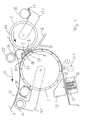
- Fig. 1
- shows, roughly schematically, a side view of a support roller winding machine, the roll change being drawn through for heavy paper types and drawn with dashed lines for light paper types.
Die Tragwalzen-Wickelmaschine weist zwei angetriebene Tragwalzen 1, 2 auf, zwischen denen ein Walzenbett 3 ausgebildet ist, in dem die Wickelrollen 4 während des Aufwickelns auf den Tragwalzen 1, 2 aufliegen. Die in Längsrichtung in Einzelbahnen aufgeteilte Materialbahn 5, vorzugsweise eine Papier- oder Kartonbahn, wird von unten, von der Tragwalze 1 umgelenkt, zwischen den Tragwalzen 1, 2 in das Walzenbett 3 geführt und auf fluchtend aufgereihte Hülsen gewickelt. Derartige Doppeltragwalzen-Wickelmaschinen sind vielfach bekannt und z. B. in der DE-OS 32 07 461 beschrieben, so daß auf Einzelteile, soweit sie nicht die Erfindung betreffen, nicht eingegangen wird.The carrier roller winding machine has two driven
Die umschlungene Tragwalze 1 ist als Saugwalze ausgebildet, sie kann zum Festhalten der Bahn 5 mit Unterdruck beaufschlagt werden. Im Bereich zwischen den beiden Tragwalzen 1, 2 ist eine maschinenbreite heb- und senkbare Stütze 6 angeordnet, die an ihrem oberen Ende ein in Richtung zur Tragwalze 1 klappbares, sich über die gesamte Arbeitsbreite erstreckendes Trennmesser 7 trägt, das so durch den Spalt zwischen den Tragwalzen 1, 2 bis in den oberen Zwickel zwischen den beiden Tragwalzen 1, 2 (Walzenbett 3) bewegt und zugleich in eine das Aufwickeln nicht störende Position abgesenkt werden kann. Unterhalb des Gelenks des Trennmessers 7 sind an der Stütze 6 über die Arbeitsbreite eine Vielzahl Rollen 8 freidrehend und federnd so gelagert, daß sie in einer Position etwas oberhalb der engsten Stelle zwischen den beiden Tragwalzen 1, 2 am Umfang der Tragwalze 1 anliegen.The wrapped
An der Einlaufseite, kurz bevor die Bahn 5 die Tragwalze 1 berührt, sind eine Perforiereinrichtung 10 und beidseits von dieser zwei Klebebandspender 11, 12 angeordnet. Die Perforiereinrichtung 10 besteht aus einem gezahnten, sich über die Arbeitsbreite erstreckenden Messer, das in die Nut eines auf der anderen Bahnseite angeordneten Gegenhalters 13 einfahrbar ist. Der Gegenhalter 13 weist neben der Nut Abstützflächen für die Bahn 5 auf, damit diese beim Perforieren und Auftragen der doppelseitig klebenden Klebebänder nicht ausweichen kann. Im vorliegenden Ausführungsbeispiel sind zu beiden Seiten der Perforiereinrichtung 10 Klebebandspender 11, 12 für schmale Klebebänder, die quer über die Bahn 5 geklebt werden, angeordnet. Alternativ dazu ist es ebenfalls möglich, ein breites, doppelseitig klebendes Klebeband zunächst aufzutragen und anschließend die Bahn 5 mittels der Perforiereinrichtung 10 durch das breite Klebeband hindurch zu schwächen.A perforating
Nach einer anderen Ausführungsform (- in Fig. 1 gestrichelt gezeichnet -) sind quer über die Arbeitsbreite eine Vielzahl von Klebebandspendern 11.1 angeordnet, die ihre Klebebänder in Bahnlaufrichtung abgeben. Dies hat den Vorteil, daß das Anbringen der Klebebänder mittels der bewegten Bahn erfolgen kann. Die Stillstandszeit der Wickelmaschine läßt sich so weiter verkürzen, falls der Klebebandauftrag beim Wiederanfahren der Maschine nach dem Perforieren durchgeführt wird.According to another embodiment (shown in dashed lines in FIG. 1), a large number of adhesive tape dispensers 11.1 are arranged across the working width and release their adhesive tapes in the direction of web travel. This has the advantage that the adhesive tapes can be attached by means of the moving web. The downtime of the winding machine can be further reduced if the tape is applied when the machine is restarted after perforating.
Zum Ausstoßen der vollen Wickelrollen 4 dient ein um die Tragwalze 1 schwenkbare Ausstoßrolle 14, die an seitlichen, um die Achse der Tragwalze 1 schwenkbaren Schwenkarmen 14.1 frei drehbar gelagert ist. Konstruktiv vorteilhaft läßt sich der Gegenhalter 13 unten an den Schwenkarmen 14.1 befestigen, so daß er durch Abschwenken der Ausstoßrolle 14 gegen die Bahn 5 bewegt werden kann. Auf bekannte Weise ist an den Schwenkarmen 14.1 im Bereich zwischen Ausstoßrolle 14 und Tragwalze 1 eine Hülseneinlegeeinrichtung 15 befestigt, z. B. eine Hülsenzange oder eine Hülsenrinne, mit der ein Satz neuer Hülsen 16 in das Walzenbett 3 eingelegt werden kann. Alternativ kann die Hülseneinlegeeinrichtung 17 auch auf bekannte Weise getrennt von der Ausstoßrolle 14 an um die Tragwalze 2 schwenkbaren Schwenkarmen 17.1 befestigt sein, um einen Satz neuer Hülsen 16 über die Tragwalze 2 in das Walzenbett 3 einzulegen. Ebenso ist es möglich, eine Wickelmaschine mit beiden Hülseneinlegeeinrichtungen 15, 17 zu versehen. Dann dient die um die Tragwalze 1 schwenkende Einrichtung 15 zum Einlegen von Hülsen mit kleinem Durchmesser, die Einrichtung 17 zum Einlegen von Hülsen mit großem Durchmesser.For ejecting the full winding rolls 4 is used a pivoting about the
Beim Aufwickeln von schweren Papiersorten wird der Rollenwechsel wie folgt durchgeführt:
Wenn die Wickelrolle 4 eine vorgegebene Bahnlänge oder einen vorgegebenen Durchmesser erreicht hat, wird die Tragwalzen-Wickelmaschine angehalten; d.h. die Antriebe der Tragwalzen 1, 2 werden abgebremst. Die Bahn 5 kommt durch die Bremskraft, die von der nicht dargestellten Abrolleinrichtung aufgebracht wird, unter Bahnzug zum Stehen. Im Bereich vor der umschlungenen Tragwalze 1 werden nun quer über die Breite der Bahn 5 zwei nebeneinanderliegende doppelseitig klebende Klebebänder von den Klebebandspendern 11, 12 aufgebracht. Gleichzeitig oder direkt anschließend wird die Materialbahn 5 mit der Perforiereinrichtung 10 über ihre gesamte Breite geschwächt. Der Grad der Schwächung wird in Abhängigkeit von der Materialsorte eingestellt, so daß die benötigte Kraft zum Trennen der Bahn 5 unabhängig von der Materialsorte immer annähernd gleich groß ist. Anschließend wird die Maschine wieder gestartet, bis die geschwächte Bahnstelle mit den beiden Klebstreifen 18, 19 sich im Walzenbett 3, jedoch noch unterhalb der Berührungslinie der noch einzulegenden neuen Hülsen 16 an der Tragwalze 1 befindet. Dort wird die Bahn 5 wieder abgestoppt und die Bremse an der Abrollvorrichtung wird arretiert, so daß die Bahn 5 mit maximaler Kraft zurückgehalten wird. Gleichfalls wird die Stütze 6 hochgefahren, so daß die Rollen 8 die Bahn 5 mit kurzem Abstand unterhalb der geschwächten Stelle auf der Tragwalze 1 festklemmen. Bei dieser Verfahrensweise wird das Trennmesser 7 nicht benutzt, daher auch nicht in Richtung zur Tragwalze 1 geklappt. Falls erforderlich, kann das Halten der Bahn 5 auf der Tragwalze 1 durch Beaufschlagen mit Unterdruck unterstützt werden.When winding heavy paper types, the roll change is carried out as follows:
When the winding roll 4 has reached a predetermined web length or a predetermined diameter, the carrier roller winding machine is stopped; ie the drives of the
Anschließend wird die volle Wickelrolle 4 mit der Ausstoßrolle 14 etwas angehoben und die Tragwalze 2 in Richtung des Pfeils 20 gegen den Uhrzeigersinn angetrieben. Sie dreht die Rolle 4 somit im Uhrzeigersinn (Pfeil 21), es wird so auf die geschwächte Bahnstelle ein Zug ausgeübt, der zum Durchtrennen der Bahn 5 an dieser Stelle führt. Die Wickelrolle 4 wird solange gedreht, bis das sich am Bahnende befindliche Klebeband 18 durch den Spalt zwischen der Ausstoßrolle 14 und der Wickelrolle 4 gezwängt wurde, so daß das Ende der Bahn 5 fest mit der Wickelrolle 4 verbunden ist. Anschließend wird die Ausstoßrolle 14 weiter in Richtung zur Tragwalze 2 geschwenkt und so die volle Wickelrolle 4 aus dem Walzenbett 3 ausgestoßen. Entweder gleichzeitig - mittels der Hülseneinlegevorrichtung 15 - oder anschließend - mittels der Hülseneinlegevorrichtung 17 - wird ein Satz neuer Hülsen 16 in das Walzenbett 3 eingelegt. Nach dem Auflegen der Druckwalze 22 werden die Tragwalzen 1, 2 erneut in Bewegung gesetzt, um den neugeschaffenen Bahnanfang mit dem Klebestreifen 19 in Kontakt mit den Hülsen 16 zu bringen. Nachdem der Bahnanfang mit dem Klebeband 19 den Spalt zwischen den Hülsen 16 und der Tragwalze 1 durchlaufen hat und so eine haltbare Klebeverbindung der Bahn 5 mit den Hülsen 16 hergestellt wurde, wird die Stütze 6 mit der Rolle 8 in eine nicht störende Position abgesenkt und die Tragwalzen-Wickelmaschine kann auf volle Wickelgeschwindigkeit beschleunigt werden.
Es ist auch möglich, vor dem Ausstoßen der vollen Rolle 4 ohne Anheben der Wickelrolle 4 zum Durchtrennen der Bahn beide Tragwalzen 1, 2 anzutreiben. Die Klebeverbindung des Endes der Bahn 5 mit der Wickelrolle 4 wird dann beim Durchlauf des Klebebandes 18 durch den Spalt zwischen der Tragwalze 1 und der Wickelrolle 4 erzeugt. Diese Verfahrensweise hat jedoch den Nachteil, daß sich die Tragwalze 1 unter der von den Rollen 8 festgeklemmten Bahn 5 durchdrehen muß und ein Zeitverlust durch ein zusätzliches Starten der Maschine auftritt.Then the full winding roll 4 is raised slightly with the
It is also possible to drive both
Beim Aufwickeln von leichten Papiersorten wird ein Rollenwechsel entsprechend, jedoch mit folgenden Änderungen durchgeführt:
Da bei leichten Papiersorten eine Schwächung der Bahn 5 nicht erforderlich ist, bleibt die Perforiereinrichtung 10 inaktiv. Falls das Bahnende an der vollen Wickelrolle 4 angeklebt werden soll, kann mit den Klebebandspendern 11 oder 12 ein Klebeband 18.1 angebracht werden. Dies erfolgt vorteilhafterweise während des Auslaufens der Maschine, während sie für den Trennvorgang abgestoppt wird. Der Bremsvorgang ist so gesteuert, daß sich nach dem Anhalten das Klebeband 18.1 im Walzenbett 3 oberhalb der Arbeitsposition 7.1 des Trennmessers 7 befindet. Zum Durchtrennen der Bahn wird die Stütze 6 soweit durch den Spalt zwischen den beiden Tragwalzen 1, 2 hochgefahren, daß sich nach dem Trennen ein ausreichend langer Bahnanfang im Tragwalzenbett 3 befindet, um den Satz neuer Hülsen 16 problemlos anzuwickeln. Die Stütze 6 wird dabei soweit hochgefahren, daß die Rollen 8 die Tragwalze 1 nicht mehr berühren. Die Bahn 5 wird ausschließlich von dem Unterdruck in der Tragwalze 1 auf deren Oberfläche gehalten. Zum Trennen der Bahn schwenkt das Messer 7 in Richtung zur Tragwalze 1, wobei um Beschädigungen zu vermeiden, ein geringer Abstand eingehalten wird. Das Durchtrennen der Bahn 5 erfolgt durch Ausstoßen der vollen Wickelrolle 4 über die Tragwalze 2 mittels der Ausstoßrolle 14, dabei wirkt das Trennmesser 7 als passive Abreißkante.
Nach dem Ausstoßen der vollen Wickelrolle 4 wird die Stütze 6 mit dem Trennmesser 7 wieder abgesenkt und ein Satz neuer Hülsen 16 eingelegt. An den Hülsen 16 sind auf bekannte Weise Klebebänder oder Leimspuren angebracht, um den neugeschaffenen Bahnanfang an ihnen zu befestigen. Das Anwickeln des Bahnanfangs an den Hülsen 16 erfolgt nach Aufsetzen der Druckwalze 22 automatisch beim Wiederanfahren der Tragwalzenmaschine durch Drehung der beiden Tragwalzen 1, 2.When winding light paper types, a roll change is carried out accordingly, but with the following changes:
Since a weakening of the
After the full winding roll 4 has been ejected, the
Claims (5)
Applications Claiming Priority (2)
| Application Number | Priority Date | Filing Date | Title |
|---|---|---|---|
| DE4003504A DE4003504A1 (en) | 1990-02-07 | 1990-02-07 | Machine for winding continuous strip of material into roll - has extractor to remove full rolls and insert new roll core |
| DE4003504 | 1990-02-07 |
Publications (3)
| Publication Number | Publication Date |
|---|---|
| EP0442038A2 true EP0442038A2 (en) | 1991-08-21 |
| EP0442038A3 EP0442038A3 (en) | 1992-03-18 |
| EP0442038B1 EP0442038B1 (en) | 1995-10-11 |
Family
ID=6399543
Family Applications (1)
| Application Number | Title | Priority Date | Filing Date |
|---|---|---|---|
| EP90119865A Expired - Lifetime EP0442038B1 (en) | 1990-02-07 | 1990-10-17 | Method and device for automatically replacing a full roll by a new winding core |
Country Status (9)
| Country | Link |
|---|---|
| US (1) | US5222679A (en) |
| EP (1) | EP0442038B1 (en) |
| JP (1) | JP3053878B2 (en) |
| AT (1) | ATE128943T1 (en) |
| BR (1) | BR9100273A (en) |
| CA (1) | CA2033615C (en) |
| DE (2) | DE4003504A1 (en) |
| ES (1) | ES2081892T3 (en) |
| FI (1) | FI103878B1 (en) |
Cited By (9)
| Publication number | Priority date | Publication date | Assignee | Title |
|---|---|---|---|---|
| WO1992006912A1 (en) * | 1990-10-15 | 1992-04-30 | Beloit Corporation | Method for effecting a set change in a winder |
| EP0585092A1 (en) * | 1992-08-26 | 1994-03-02 | Ykk Corporation | Automatic winding machine for tape-like articles |
| EP0733569A2 (en) * | 1995-03-23 | 1996-09-25 | Maschinenfabrik GOEBEL GmbH | Winding device with housing |
| EP0934895A2 (en) * | 1998-02-05 | 1999-08-11 | Voith Sulzer Papiertechnik Patent GmbH | Method of guiding a material web from a winding roll to a winding core and winding device |
| DE19808041A1 (en) * | 1998-02-26 | 1999-09-09 | Voith Sulzer Papiertech Patent | Method for transferring web of material, e.g. paper, from reel to roll core using double sided adhesive tape |
| US6199476B1 (en) | 1998-04-06 | 2001-03-13 | Voith Sulzer Papiertechnik Patent Gmbh | Roll machine and process for operating the same |
| EP1652803A2 (en) | 2004-10-29 | 2006-05-03 | Voith Paper Patent GmbH | Winding machine |
| DE202014003408U1 (en) | 2013-09-03 | 2014-07-03 | Raumaster Paper Oy | Apparatus for applying adhesive to the roll and sleeve |
| WO2015024682A1 (en) * | 2013-08-23 | 2015-02-26 | Voith Patent Gmbh | Winding device for fiber webs |
Families Citing this family (30)
| Publication number | Priority date | Publication date | Assignee | Title |
|---|---|---|---|---|
| DE4029180A1 (en) * | 1990-09-14 | 1992-03-19 | Jagenberg Ag | METHOD AND DEVICE FOR CHANGING REELS |
| US5413656A (en) * | 1990-09-14 | 1995-05-09 | Jagenberg Aktiengesellschaft | Method and device for exchanign windings rolls |
| DE4029914A1 (en) * | 1990-09-21 | 1992-03-26 | Jagenberg Ag | CARRIER ROLLING MACHINE |
| DE4115406A1 (en) * | 1991-05-10 | 1992-11-12 | Jagenberg Ag | WINDING MACHINE FOR WINDING MATERIALS |
| IT1265841B1 (en) * | 1993-02-15 | 1996-12-12 | Perini Fabio Spa | REWINDING MACHINE PERFECTED FOR WINDING WITHOUT CENTRAL CORE WITH SUPPORT SURFACE FOR THE ROLL IN FORMATION. |
| DE4334029C2 (en) * | 1993-10-06 | 1998-01-22 | Jagenberg Papiertech Gmbh | Carrier roll winding machine |
| DE4415316C2 (en) * | 1994-05-02 | 1998-03-12 | Kleinewefers Gmbh | Roll winding machine |
| DE19519306A1 (en) * | 1995-05-26 | 1996-11-28 | Voith Sulzer Papiermasch Gmbh | Method and device for the automatic cutting and winding of a paper web |
| US5950958A (en) * | 1995-10-04 | 1999-09-14 | Valmet Corporation | Method in winding of a web, in particular of a paper or board web |
| CA2239185C (en) * | 1995-10-04 | 2002-07-02 | Valmet Corporation | Method in winding of a web, in particular of a paper or board web |
| DE29610199U1 (en) | 1996-06-13 | 1997-10-16 | Beloit Technologies, Inc., Wilmington, Del. | Cross cutting device for winding machines |
| DE19624716A1 (en) * | 1996-06-21 | 1996-11-21 | Voith Sulzer Papiermasch Gmbh | Winding machine for coiling moving paper web |
| DE19653006B4 (en) * | 1996-12-19 | 2004-04-29 | Voith Sulzer Papiermaschinen Gmbh | Winding machine for winding a material web |
| DE29710225U1 (en) * | 1997-06-13 | 1998-10-22 | Beloit Technologies, Inc., Wilmington, Del. | Web insertion arrangement for a winding machine |
| DE19743070A1 (en) * | 1997-09-30 | 1999-04-01 | Jagenberg Papiertech Gmbh | Carrier roll winding machine |
| DE19801599A1 (en) * | 1998-01-17 | 1999-07-22 | Voith Sulzer Papiertech Patent | Carrier roller winding device |
| DE19839916A1 (en) * | 1998-09-02 | 2000-03-09 | Jagenberg Papiertech Gmbh | Method and apparatus for reducing the volume or pressure of a fluid being dragged into a gap by moving surfaces |
| DE19848814A1 (en) * | 1998-10-22 | 2000-04-27 | Voith Sulzer Papiertech Patent | Paper web winding machine with web perforation unit reduces the time taken to change drums |
| DE10030582C1 (en) * | 2000-06-21 | 2002-01-10 | Voith Paper Patent Gmbh | Method for winding a material web and winding device |
| US6629662B2 (en) * | 2001-06-20 | 2003-10-07 | Tuftco Finishing Systems, Inc. | Method and apparatus for rolling carpet |
| US6877689B2 (en) * | 2002-09-27 | 2005-04-12 | C.G. Bretting Mfg. Co., Inc. | Rewinder apparatus and method |
| US7175127B2 (en) * | 2002-09-27 | 2007-02-13 | C.G. Bretting Manufacturing Company, Inc. | Rewinder apparatus and method |
| US7114675B1 (en) * | 2003-05-22 | 2006-10-03 | Kohler Herbert B | Dual-drum winding machine |
| DE10329690B4 (en) * | 2003-07-02 | 2006-03-09 | Voith Paper Patent Gmbh | Method for introducing a web, in particular a paper or board web, into a reel winder and reel winder |
| US7900673B2 (en) * | 2004-09-28 | 2011-03-08 | Valco Cincinnati, Inc. | Tissue manufacturing/handling device |
| US20080223975A1 (en) * | 2007-03-14 | 2008-09-18 | Miroslav Planeta | Reversible surface winder |
| US20090250544A1 (en) * | 2008-04-08 | 2009-10-08 | Pasquale Robert A | Tail Free Transfer Winder |
| US10427903B2 (en) | 2016-03-04 | 2019-10-01 | The Procter & Gamble Company | Leading edge device for a surface winder |
| US10427902B2 (en) | 2016-03-04 | 2019-10-01 | The Procter & Gamble Company | Enhanced introductory portion for a surface winder |
| US10442649B2 (en) | 2016-03-04 | 2019-10-15 | The Procter & Gamble Company | Surface winder for producing logs of convolutely wound web materials |
Citations (4)
| Publication number | Priority date | Publication date | Assignee | Title |
|---|---|---|---|---|
| GB2065081A (en) * | 1979-12-05 | 1981-06-24 | Jagenberg Werke Ag | Apparatus for accurately inserting winding cores in winding machines |
| DE8107184U1 (en) * | 1981-03-13 | 1982-07-01 | J.M. Voith Gmbh, 7920 Heidenheim | Device for separating a web of material in a double roller winding machine |
| GB2183610A (en) * | 1985-11-28 | 1987-06-10 | Waertsilae Oy Ab | Web winding method and winder |
| GB2188911A (en) * | 1986-04-09 | 1987-10-14 | Jagenberg Ag | Automatic separating and winding of a material web |
Family Cites Families (6)
| Publication number | Priority date | Publication date | Assignee | Title |
|---|---|---|---|---|
| DE2920707C2 (en) * | 1979-05-22 | 1990-05-31 | Jagenberg-Werke AG, 4000 Düsseldorf | Process and double roller winding machine for automatically separating and winding a web of material |
| DE3151256C2 (en) * | 1981-01-09 | 1983-10-06 | Jagenberg-Werke Ag, 4000 Duesseldorf | Device on shaftless winding machines |
| US4422588A (en) * | 1981-09-28 | 1983-12-27 | The Black Clawson Company | Slitter-rewinder system |
| AT376950B (en) * | 1981-12-24 | 1985-01-25 | Jagenberg Werke Ag | DEVICE ON AXLE WRAPPING MACHINES |
| DE3207461A1 (en) * | 1982-03-02 | 1983-09-22 | Jagenberg-Werke AG, 4000 Düsseldorf | Rolling machine |
| FI69819C (en) * | 1983-05-03 | 1986-05-26 | Waertsilae Oy Ab | ANORDINATION FOER BANRULLNING |
-
1990
- 1990-02-07 DE DE4003504A patent/DE4003504A1/en not_active Withdrawn
- 1990-10-17 DE DE59009768T patent/DE59009768D1/en not_active Expired - Fee Related
- 1990-10-17 AT AT90119865T patent/ATE128943T1/en not_active IP Right Cessation
- 1990-10-17 ES ES90119865T patent/ES2081892T3/en not_active Expired - Lifetime
- 1990-10-17 EP EP90119865A patent/EP0442038B1/en not_active Expired - Lifetime
-
1991
- 1991-01-04 CA CA002033615A patent/CA2033615C/en not_active Expired - Fee Related
- 1991-01-23 BR BR919100273A patent/BR9100273A/en not_active IP Right Cessation
- 1991-02-06 JP JP3015372A patent/JP3053878B2/en not_active Expired - Fee Related
- 1991-02-06 US US07/653,352 patent/US5222679A/en not_active Expired - Fee Related
- 1991-02-06 FI FI910574A patent/FI103878B1/en not_active IP Right Cessation
Patent Citations (4)
| Publication number | Priority date | Publication date | Assignee | Title |
|---|---|---|---|---|
| GB2065081A (en) * | 1979-12-05 | 1981-06-24 | Jagenberg Werke Ag | Apparatus for accurately inserting winding cores in winding machines |
| DE8107184U1 (en) * | 1981-03-13 | 1982-07-01 | J.M. Voith Gmbh, 7920 Heidenheim | Device for separating a web of material in a double roller winding machine |
| GB2183610A (en) * | 1985-11-28 | 1987-06-10 | Waertsilae Oy Ab | Web winding method and winder |
| GB2188911A (en) * | 1986-04-09 | 1987-10-14 | Jagenberg Ag | Automatic separating and winding of a material web |
Cited By (17)
| Publication number | Priority date | Publication date | Assignee | Title |
|---|---|---|---|---|
| WO1992006912A1 (en) * | 1990-10-15 | 1992-04-30 | Beloit Corporation | Method for effecting a set change in a winder |
| EP0585092A1 (en) * | 1992-08-26 | 1994-03-02 | Ykk Corporation | Automatic winding machine for tape-like articles |
| US5419511A (en) * | 1992-08-26 | 1995-05-30 | Yoshida Kogyo K.K. | Automatic winding machine for tape-like articles |
| EP0733569A2 (en) * | 1995-03-23 | 1996-09-25 | Maschinenfabrik GOEBEL GmbH | Winding device with housing |
| EP0733569A3 (en) * | 1995-03-23 | 1997-05-21 | Goebel Gmbh Maschf | Winding device with housing |
| US6230998B1 (en) | 1998-02-05 | 2001-05-15 | Voith Sulzer Papiertechnik Patent Gmbh | Method for transferring a web of material from a wound roll onto a winding tube, and winding apparatus |
| DE19804411A1 (en) * | 1998-02-05 | 1999-08-19 | Voith Sulzer Papiertech Patent | Method for transferring a material web from a winding roll to a winding tube and winding device |
| EP0934895A3 (en) * | 1998-02-05 | 2000-02-09 | Voith Sulzer Papiertechnik Patent GmbH | Method of guiding a material web from a winding roll to a winding core and winding device |
| EP0934895A2 (en) * | 1998-02-05 | 1999-08-11 | Voith Sulzer Papiertechnik Patent GmbH | Method of guiding a material web from a winding roll to a winding core and winding device |
| DE19808041A1 (en) * | 1998-02-26 | 1999-09-09 | Voith Sulzer Papiertech Patent | Method for transferring web of material, e.g. paper, from reel to roll core using double sided adhesive tape |
| EP0945380A1 (en) * | 1998-02-26 | 1999-09-29 | Voith Sulzer Papiertechnik Patent GmbH | Method for transferring a material web from a winding roll to a core and winding unit |
| US6086010A (en) * | 1998-02-26 | 2000-07-11 | Voith Sulzer Papiertechnik Patent Gmbh | Process for transferring a material web from a winding roll to a winding sleeve and winding device |
| US6199476B1 (en) | 1998-04-06 | 2001-03-13 | Voith Sulzer Papiertechnik Patent Gmbh | Roll machine and process for operating the same |
| EP1652803A2 (en) | 2004-10-29 | 2006-05-03 | Voith Paper Patent GmbH | Winding machine |
| EP1652803A3 (en) * | 2004-10-29 | 2007-11-07 | Voith Patent GmbH | Winding machine |
| WO2015024682A1 (en) * | 2013-08-23 | 2015-02-26 | Voith Patent Gmbh | Winding device for fiber webs |
| DE202014003408U1 (en) | 2013-09-03 | 2014-07-03 | Raumaster Paper Oy | Apparatus for applying adhesive to the roll and sleeve |
Also Published As
| Publication number | Publication date |
|---|---|
| ES2081892T3 (en) | 1996-03-16 |
| FI103878B (en) | 1999-10-15 |
| CA2033615C (en) | 2000-10-10 |
| JP3053878B2 (en) | 2000-06-19 |
| ATE128943T1 (en) | 1995-10-15 |
| FI910574A (en) | 1991-08-08 |
| CA2033615A1 (en) | 1991-08-08 |
| EP0442038B1 (en) | 1995-10-11 |
| DE59009768D1 (en) | 1995-11-16 |
| FI910574A0 (en) | 1991-02-06 |
| US5222679A (en) | 1993-06-29 |
| FI103878B1 (en) | 1999-10-15 |
| EP0442038A3 (en) | 1992-03-18 |
| JPH04213540A (en) | 1992-08-04 |
| BR9100273A (en) | 1991-10-22 |
| DE4003504A1 (en) | 1991-08-08 |
Similar Documents
| Publication | Publication Date | Title |
|---|---|---|
| EP0442038B1 (en) | Method and device for automatically replacing a full roll by a new winding core | |
| DE60012144T2 (en) | RAILWAY DEVICE WITH SEPARATION AND DELIVERY DEVICE | |
| DE69720214T2 (en) | WINDING DEVICE FOR A MATERIAL RAIL TO BE REWINDED | |
| AT399856B (en) | METHOD AND DEVICE FOR AUTOMATICALLY SEPARATING AND REWINDING A MATERIAL | |
| EP0500841B1 (en) | Process and device for changing winding rollers | |
| EP0299181B1 (en) | Unwinding device for paper or cardboard web reels or similar | |
| DE2638368C2 (en) | Process and double roller winding machine for changing laps after winding webs | |
| DE4141242C2 (en) | ||
| EP0672015B1 (en) | King roll winding machine | |
| DE4115406A1 (en) | WINDING MACHINE FOR WINDING MATERIALS | |
| DE4336298A1 (en) | Unwinding apparatus with a splice device | |
| DE2909736C3 (en) | Process and double drum roller for rolling up endlessly fed webs | |
| EP1163178B1 (en) | Device for connecting material webs | |
| EP0506896B1 (en) | King roll reeler | |
| DE3308059C2 (en) | ||
| DE4436719A1 (en) | Splicer for packaging material webs wound in a bobbin-like manner | |
| DE4122411C2 (en) | Process for replacing and adjusting pre-printed strip material in a production machine | |
| EP0379861B1 (en) | Device for joining sheets together | |
| WO1992007783A1 (en) | Device for cutting through a strip of material | |
| EP0683122A1 (en) | Pasting means for splicing webs wound into driven rolls | |
| DE2344870B2 (en) | Device for end-to-end connection of two tracks | |
| DE69903008T2 (en) | HIGH-SPEED CUTTING DEVICE | |
| DE4415316C2 (en) | Roll winding machine | |
| DE4222880C2 (en) | Splicevorrichtung | |
| EP0930261B1 (en) | Method and device for winding of a slitted web to rolls |
Legal Events
| Date | Code | Title | Description |
|---|---|---|---|
| PUAI | Public reference made under article 153(3) epc to a published international application that has entered the european phase |
Free format text: ORIGINAL CODE: 0009012 |
|
| AK | Designated contracting states |
Kind code of ref document: A2 Designated state(s): AT CH DE ES FR GB IT LI NL SE |
|
| PUAL | Search report despatched |
Free format text: ORIGINAL CODE: 0009013 |
|
| AK | Designated contracting states |
Kind code of ref document: A3 Designated state(s): AT CH DE ES FR GB IT LI NL SE |
|
| 17P | Request for examination filed |
Effective date: 19920215 |
|
| 17Q | First examination report despatched |
Effective date: 19940505 |
|
| GRAA | (expected) grant |
Free format text: ORIGINAL CODE: 0009210 |
|
| AK | Designated contracting states |
Kind code of ref document: B1 Designated state(s): AT CH DE ES FR GB IT LI NL SE |
|
| PG25 | Lapsed in a contracting state [announced via postgrant information from national office to epo] |
Ref country code: NL Free format text: LAPSE BECAUSE OF NON-PAYMENT OF DUE FEES Effective date: 19951011 |
|
| REF | Corresponds to: |
Ref document number: 128943 Country of ref document: AT Date of ref document: 19951015 Kind code of ref document: T |
|
| ITF | It: translation for a ep patent filed | ||
| PG25 | Lapsed in a contracting state [announced via postgrant information from national office to epo] |
Ref country code: LI Effective date: 19951031 Ref country code: CH Effective date: 19951031 |
|
| ET | Fr: translation filed | ||
| REF | Corresponds to: |
Ref document number: 59009768 Country of ref document: DE Date of ref document: 19951116 |
|
| GBT | Gb: translation of ep patent filed (gb section 77(6)(a)/1977) |
Effective date: 19951024 |
|
| NLV1 | Nl: lapsed or annulled due to failure to fulfill the requirements of art. 29p and 29m of the patents act | ||
| REG | Reference to a national code |
Ref country code: ES Ref legal event code: FG2A Ref document number: 2081892 Country of ref document: ES Kind code of ref document: T3 |
|
| REG | Reference to a national code |
Ref country code: CH Ref legal event code: PL |
|
| PLBE | No opposition filed within time limit |
Free format text: ORIGINAL CODE: 0009261 |
|
| STAA | Information on the status of an ep patent application or granted ep patent |
Free format text: STATUS: NO OPPOSITION FILED WITHIN TIME LIMIT |
|
| 26N | No opposition filed | ||
| REG | Reference to a national code |
Ref country code: GB Ref legal event code: IF02 |
|
| PGFP | Annual fee paid to national office [announced via postgrant information from national office to epo] |
Ref country code: GB Payment date: 20020924 Year of fee payment: 13 |
|
| PGFP | Annual fee paid to national office [announced via postgrant information from national office to epo] |
Ref country code: FR Payment date: 20021017 Year of fee payment: 13 |
|
| PGFP | Annual fee paid to national office [announced via postgrant information from national office to epo] |
Ref country code: AT Payment date: 20021018 Year of fee payment: 13 |
|
| PGFP | Annual fee paid to national office [announced via postgrant information from national office to epo] |
Ref country code: ES Payment date: 20031006 Year of fee payment: 14 |
|
| PG25 | Lapsed in a contracting state [announced via postgrant information from national office to epo] |
Ref country code: GB Free format text: LAPSE BECAUSE OF NON-PAYMENT OF DUE FEES Effective date: 20031017 Ref country code: AT Free format text: LAPSE BECAUSE OF NON-PAYMENT OF DUE FEES Effective date: 20031017 |
|
| GBPC | Gb: european patent ceased through non-payment of renewal fee |
Effective date: 20031017 |
|
| PG25 | Lapsed in a contracting state [announced via postgrant information from national office to epo] |
Ref country code: FR Free format text: LAPSE BECAUSE OF NON-PAYMENT OF DUE FEES Effective date: 20040630 |
|
| REG | Reference to a national code |
Ref country code: FR Ref legal event code: ST |
|
| PG25 | Lapsed in a contracting state [announced via postgrant information from national office to epo] |
Ref country code: ES Free format text: LAPSE BECAUSE OF NON-PAYMENT OF DUE FEES Effective date: 20041018 |
|
| PGFP | Annual fee paid to national office [announced via postgrant information from national office to epo] |
Ref country code: SE Payment date: 20051013 Year of fee payment: 16 |
|
| PG25 | Lapsed in a contracting state [announced via postgrant information from national office to epo] |
Ref country code: IT Free format text: LAPSE BECAUSE OF NON-PAYMENT OF DUE FEES;WARNING: LAPSES OF ITALIAN PATENTS WITH EFFECTIVE DATE BEFORE 2007 MAY HAVE OCCURRED AT ANY TIME BEFORE 2007. THE CORRECT EFFECTIVE DATE MAY BE DIFFERENT FROM THE ONE RECORDED. Effective date: 20051017 |
|
| REG | Reference to a national code |
Ref country code: ES Ref legal event code: FD2A Effective date: 20041018 |
|
| PG25 | Lapsed in a contracting state [announced via postgrant information from national office to epo] |
Ref country code: SE Free format text: LAPSE BECAUSE OF NON-PAYMENT OF DUE FEES Effective date: 20061018 |
|
| EUG | Se: european patent has lapsed | ||
| PGFP | Annual fee paid to national office [announced via postgrant information from national office to epo] |
Ref country code: DE Payment date: 20071025 Year of fee payment: 18 |
|
| PG25 | Lapsed in a contracting state [announced via postgrant information from national office to epo] |
Ref country code: DE Free format text: LAPSE BECAUSE OF NON-PAYMENT OF DUE FEES Effective date: 20090501 |