EP0442036B1 - Leaf spring cambering method and apparatus - Google Patents
Leaf spring cambering method and apparatus Download PDFInfo
- Publication number
- EP0442036B1 EP0442036B1 EP90119182A EP90119182A EP0442036B1 EP 0442036 B1 EP0442036 B1 EP 0442036B1 EP 90119182 A EP90119182 A EP 90119182A EP 90119182 A EP90119182 A EP 90119182A EP 0442036 B1 EP0442036 B1 EP 0442036B1
- Authority
- EP
- European Patent Office
- Prior art keywords
- mold
- leaf spring
- cambering
- molds
- fingers
- Prior art date
- Legal status (The legal status is an assumption and is not a legal conclusion. Google has not performed a legal analysis and makes no representation as to the accuracy of the status listed.)
- Expired - Lifetime
Links
Images


Classifications
-
- B—PERFORMING OPERATIONS; TRANSPORTING
- B21—MECHANICAL METAL-WORKING WITHOUT ESSENTIALLY REMOVING MATERIAL; PUNCHING METAL
- B21D—WORKING OR PROCESSING OF SHEET METAL OR METAL TUBES, RODS OR PROFILES WITHOUT ESSENTIALLY REMOVING MATERIAL; PUNCHING METAL
- B21D53/00—Making other particular articles
- B21D53/88—Making other particular articles other parts for vehicles, e.g. cowlings, mudguards
- B21D53/886—Making other particular articles other parts for vehicles, e.g. cowlings, mudguards leaf springs
-
- B—PERFORMING OPERATIONS; TRANSPORTING
- B21—MECHANICAL METAL-WORKING WITHOUT ESSENTIALLY REMOVING MATERIAL; PUNCHING METAL
- B21F—WORKING OR PROCESSING OF METAL WIRE
- B21F37/00—Manufacture of rings from wire
-
- Y—GENERAL TAGGING OF NEW TECHNOLOGICAL DEVELOPMENTS; GENERAL TAGGING OF CROSS-SECTIONAL TECHNOLOGIES SPANNING OVER SEVERAL SECTIONS OF THE IPC; TECHNICAL SUBJECTS COVERED BY FORMER USPC CROSS-REFERENCE ART COLLECTIONS [XRACs] AND DIGESTS
- Y10—TECHNICAL SUBJECTS COVERED BY FORMER USPC
- Y10T—TECHNICAL SUBJECTS COVERED BY FORMER US CLASSIFICATION
- Y10T29/00—Metal working
- Y10T29/49—Method of mechanical manufacture
- Y10T29/49609—Spring making
- Y10T29/49611—Spring making for vehicle or clutch
Definitions
- This invention relates to a method of cambering a leaf spring according to the preamble of claim 1 and an apparatus according to the preamble of claim 2.
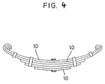
- Land transportation vehicles such as railway trains and trucks are provided with suitable suspension devices made by a plurality of leaf springs 10 as shown in Fig. 4.
- leaf spring 10 is made of a rolled material with a necessary thickness which is, after the process of opening an eyeend at one or both ends of a plate material, or tapering the other end thereof, given a necessary "deflection", or camber, in the state where the whole material is heated.
- cambers There are various types of cambers: the curvature gradually reduces or increases from the center toward both ends; the central part is formed flat, etc., depending on the use or load stress applied.
- Fig. 5 shows an example of prior art apparatus 12 for cambering leaf springs 10.
- the apparatus 12 basically consists of an upper mold 14 and a lower mold 16, and the upper mold 14 is of a female or concave shape, while the lower mold 16 of a male or convex shape.
- a leaf spring 10 immediately after being heated to the hot process temperature is inserted between these upper mold 14 and the lower mold 16, and then the upper mold 14 is forced to approach the lower mold 16 to give the plate 10 the camber in accordance with the shape of the molds 14 and 16.
- This cambered leaf spring 10 is then tempered by immersing it in a tempering oil carried within an oil tank.
- cambered leaf spring 10 is immersed in the oil without any constraint for carrying out tempering, it is distorted during the cooling process.
- a countermeasure for it is proposed in which the cambered leaf spring 10 is constrained as it is, and immersed in the oil in this state to prevent the distortion which may occur by the cooling.
- the distortion preventive means shown in Fig. 6 has a plurality of movable claw members 22 provided on a conveyor 20 circulatable in an oil tank 18, which are designed to mechanically hold a leaf spring material 10 at strategic positions.
- the leaf spring 10 to which the required camber has been given by said cambering apparatus 12 is held by a group of claws 22 locating at the carry-in side of the oil tank 18, and the conveyor 20 is then circulated with the leaf spring 10 as held thereon immersing them in the oil to carry out tempering.
- the distortion preventive means shown in Fig. 7 rotatably supports therein an octagonal column-shaped main body 24.
- the main body 24 has a cambering apparatus 12 on each surface and the lower part of the main body 24 is designed to be immersed into the oil tank 18.
- a heated straight leaf spring material 10 is loaded on the cambering apparatus 12 locating above the oil level and held between the upper mold 14 and the lower mold 16 to carry out cambering. Then, the main body 24 is rotated in the above state to immerse the cambered leaf spring 10 into the oil carried in the oil tank 18 as it is held between the upper mold 14 and the lower mold 16.
- the leaf spring material 10 is cambered by pressing it between an upper mold 14 and a lower mold 16 of the cambering apparatus 12, and then the cambering apparatus 12 is immersed into the oil carried in an oil tank 18.
- the cambering apparatus 12 within the oil tank 18 is circulatably fed by an appropriate carrying means to carry out tempering of the cambered leaf spring 10 loaded in the cambering apparatus 12.
- cambered leaf springs 10 For manufacturing such cambered leaf springs 10, there are two kinds of methods; 1 to effect cambering of leaf springs 10 of the same shape and specification continuously by the group (the industry calls this method “Group making”), and 2 a family of leaf springs 10 from the main leaf 10 to the smaller leaves 10 constituting a suspension device are cambered (the industry calls this method "Family making”). It depends on the users' choice considering the application and other factors which method is used for cambering leaf springs. In the Group making method, a required number of leaf springs of the same shape are cambered by the lot, and only when the shape of camber is changed, the upper mold 14 and the lower mold 16 of the cambering apparatus 12 are replaced.
- the Family making method the family of leaves are all allowed to have slightly different cambers, so that the upper mold 14 and the lower mold 16 have to be replaced each time one leaf 10 is cambered. Therefore, the latter method involves an extremely troublesome replacement work and increased loss time.
- the conventional cambering systems failed to meet the needs of the industry in this respect. Whether the Group making method or the Family making method it may be, many kinds of upper molds 14 and lower molds 16 corresponding to a variety of camber size requirements are necessary, leading to great increase in the production cost. Moreover, these molds have to be stored in groups of the same type, requiring an enormous storage space, giving rise to problems that their storage and maintenance are complicated and so on.
- the method mentioned referring to Fig. 9 has a merit of minimizing distortion compared with the methods shown in Figs. 6 through 8, but suffers a disadvantage of extremely low productivity. Further, the methods shown in Figs. 6 through 9 involve such common demerit that they require very troublesome work including adjustment of the claw members 22 for properly constraining the leaf springs 10 and for replacing the molds 14 and 16 according to the order changes of the leaf spring 10, and such setup procedures require much time. Moreover, the methods mentioned referring to Figs. 6 through 9 also suffer problems that, since the cambering apparatus 12 itself is immersed in the oil for carrying out tempering of the leaf springs, a number of molds 14 and 16 corresponding to the respective camber specifications have to be prepared, leading to increased production cost.
- the mold fingers can automatically be positioned based on the numerical data inputted beforehand, change of mold shape in accordance with the order changes can be carried out speedily. Moreover, the mold adjustment requires no direct intervention of operators, leading to labor and power saving.
- Fig. 1 shows schematically the constitution of an embodiment of the cambering/tempering apparatus according to this invention.
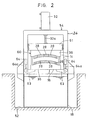
- Fig. 2 shows schematically a partially cutaway view of the hydraulic press shown in Fig. 1.
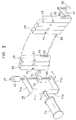
- Fig. 3 shows schematically a perspective view of the mold finger adjuster disposed in the setup unit shown in Fig. 1.
- Fig. 4 illustrates a suspension device comprising leaf springs.
- Fig. 5 illustrates a prior art cambering apparatus.
- Fig. 6 shows schematically a perspective view of a prior art tempering apparatus.
- Fig. 7 shows schematically a perspective view of a prior art cambering/tempering apparatus.
- Fig. 8 shows schematically a perspective view of another prior art cambering/tempering apparatus.
- Fig. 9 shows schematically a perspective view of still another prior art cambering/tempering apparatus.
- Fig. 1 shows schematically a constitution of an examplary cambering/tempering apparatus in which the cambering method can suitably be practiced.
- the cambering/tempering apparatus 50 basically comprises an oil tank 18 installed in a pit 52 dug to a required depth from the installation surface, a hydraulic press 54 provided above said oil tank 18 at one longitudinal end protion, an unloading device 56 provided above said oil tank 18 at the other longitudinal end portion, and a setup unit 58 disposed at an appropriate position.
- the process of cambering and tempering a leaf spring 10 and changing of the shapes of the upper mold 14 and the lower mold 16 is performed by circulating the independent unit of cambering cassette 60 consisting of the upper mold 14 and the lower mold 16 within the cambering/tempering apparatus 50.
- a base frame 26 having a rectangular shape is installed on the top of the oil tank 18, and a hydraulic cylinder 32 is inversely provided on the top of this base frame 26 with the piston rod 32a thereof extending into the base frame 26.
- a head 61 is disposed to be ascendable or descendable, to which said piston rod 32a is connected. Accordingly, when the hydraulic cylinder 32 is driven in the positive or negative direction, the head 61 can be ascended or descended within the base frame 26.
- the head 61 of the hydraulic press 54 functions to descend the upper mold 14 in the cambering cassette 60 as described later,while the head 61 of the unloading device 56 functions to ascend said upper mold 14.
- each of the support members 63 is adapted to extend its one end into the passage 62, while the other end thereof is connected to the piston rod 64a of the cylinder 64 installed within the base frame 26.
- the cambering cassette 60 consists of an upper mold 14 and a lower mold 16 which can be brought closer or farther relative to each other, and each mold comprises a multiplicity of mold fingers 28 disposed in each holder 36 in the same manner as in the foregoing embodiment.
- said cambering cassette 60 itself is immersed into the oil, so that the adjustment of the mold fingers is designed to be performed in a setup unit 58 to be described later.
- a slot 65 is defined in each of the mold fingers 28, as shown in Fig. 3, and pivotal shafts 66 are inserted through the slots of all the mold fingers 28 disposed to the lower mold 16 and the upper mold 14, respectively.
- These pivotal shafts 66 are each designed to be turned within a predetermined angle range by means of a cam 67 and a cylinder 68 provided at one end thereof.
- an eccentric cam 69 is fixed on said pivotal shaft 66 at each position corresponding to the slot 65 of each finger 28.
- this eccentric cam 69 abuts against the inner wall of the slot 65 to prevent shifting off of the mold finger 28, whereas when the pivotal shaft 66 is turned counterclockwise, the finger 28 is designed to be shiftable.
- a hole 70 is formed at an appropriate position of each mold finger 28, which is used when the mold finger 28 is adjusted in the setup unit 58 to be described later.
- the setup unit 58 is for adjusting the protruding length of each mold finger 28 of the upper mold 14 and the lower mold 16 from the holder 36 to change the cambering mold shape to be formed thereby. While this apparatus has adjusters 75, as shown in Fig. 3, provided for each of the respective mold fingers 28 of the upper mold 14 and the lower mold 16, only one adjuster 75 is shown in the drawing.
- a threaded shaft 38 is rotatably supported between the upper and lower horizontal members 71, 71a thereof, and a servo motor 42 is attached on the upper end of said threaded shaft 38.
- a nut 73 On the threaded shaft 38, screwed is a nut 73 having a pin 72 screwed therein which can be inserted into the hole 70 formed in each mold finger 28.
- This nut 73 is designed to be free from the rotation of the threaded shaft 38 by an appropriate means (not shown), so that the nut 73 can be ascended or descended along the threaded shaft 38 by rotating said servo motor 42 normally or reversely.
- a piston rod 74a of a cylinder 74 By driving said cylinder 74 in the positive or negative direction, the support frame 71 can be advanced or retracted correspondingly. Namely, when said cambering cassette 60 is set in the setup unit 58, said cylinder 74 is driven in the direction so as to extend the piston rod 74a to insert the pin 72 of the nut 73 provided on said threaded shaft 38 into the hole 70 of the mold finger 28. The servo motor 42 is then driven normally or reversely to advance or retract the mold finger 28.
- a position detector 48 is provided for each servo motor 42 to monitor constantly the accurate position of the mold finger 28 in the same manner as in the foregoing embodiment.
- the signal from the position detector 48 concerning the current position of the mold finger 28 is designed to be inputted to the control means (not shown).
- the effect of the cambering method resulted from the operation of the cambering/tempering apparatus having the aforesaid constitution will be explained.
- the upper mold 14 and the lower mold 16 are separated and the cambering cassette 60 is set in place in the setup unit 58 with all the mold fingers 28 thereof being released from the locking by the eccentric cams 69.
- the cylinder 74 of the adjuster 75 is driven to bring the support frame 71 closer to the mold finger 28 until said pin 72 is inserted into the hole 70 of the finger 28.
- the operation of said servo motor 42 is controlled based on the data concerning the cambering mold shape preliminarily inputted to the control means to effect adjustment of the mold finger 28.
- said cylinder 68 is driven in the desired direction to turn the eccentric cams 69 and lock the mold fingers 28 at predetermined positions, respectively.
- the adjuster 75 is with drawn from the mould fingers 28.
- the cambering cassette 60 is forwarded to the hydraulic press 54 and set therein by the support members 63, as shown in Fig. 2.
- the hydraulic cylinder 32 is driven so as to descend the upper mold 14 through the head 61, whereby the leaf spring material 10 is allowed to have the desired camber by the tight pressing between the upper mold 14 and the lower mold 16.
- an appropriate means is used to keep both molds 14 and 16 holding the leaf spring 10 therebetween.
- the cambering cassette 60 descends through the passage 62 and is immersed into the oil in the oil tank 18, whereby the leaf spring 10 is tempered as the cambering cassette 60 is carried through the oil tank 18 by an appropriate means (not shown). In this process, since the leaf spring 10 is entirely held between the upper mold 14 and the lower mold 16, any distortion which may otherwise occur can be prevented.
- the cambering cassette 60 After carried to the position immediately below the unloading device 56, the cambering cassette 60, as shown in Fig. 4, is taken out from the oil tank 18 and set in the unloading apparatus 56 by the support members 63, wherein the head 61 is holding the upper mold 14, while the lower mold 16 is immobilized with an appropriate means.
- the upper mold 14 ascends to release the leaf spring 10.
- the leaf spring 10 subjected to cambering and tempering is taken out of the cambering cassette 60 by means of a take-out device (not shown) and forwarded to the subsequent process.
- the cambering cassette 60 is forwarded from the unloading device 56 to the setup unit 58 and is set in place there, wherein the upper mold 14 and the lower mold 16 are already separated from each other, so the cylinder 68 is driven in the predetermined direction to release the mold fingers 28 from the locking by the eccentric cams 69. Then, each mold finger 28 of the upper mold 14 and the lower mold 16 is adjusted in the setup unit 58 in the aforesaid manner, and the desired cambering mold shape is formed on the opposing surfaces of the molds 14 and 16. After the adjustment of the mold fingers 28, the cambering cassette 60 is forwarded again into the hydraulic press 54, the aforesaid cycle is repeated to form leaf springs 10 of the different camber shape.
- the adjustment of the mold fingers 28 made by controlling the operation of the servo motors 42 based on the data preliminarily inputted to the control means causes to reduce the operation loss time associated with the order changes. Since the leaf spring 10 is immersed in the oil as it is constrained in the cambering cassette 60, any distortion which may otherwise occur during tempering can be prevented.
Abstract
Description
- This invention relates to a method of cambering a leaf spring according to the preamble of claim 1 and an apparatus according to the preamble of claim 2.
- Land transportation vehicles such as railway trains and trucks are provided with suitable suspension devices made by
a plurality ofleaf springs 10 as shown in Fig. 4.Such leaf spring 10 is made of a rolled material with a necessary thickness which is, after the process of opening an eyeend at one or both ends of a plate material, or tapering the other end thereof, given a necessary "deflection", or camber, in the state where the whole material is heated. There are various types of cambers: the curvature gradually reduces or increases from the center toward both ends; the central part is formed flat, etc., depending on the use or load stress applied. - Fig. 5 shows an example of
prior art apparatus 12 for camberingleaf springs 10. Theapparatus 12 basically consists of anupper mold 14 and alower mold 16, and theupper mold 14 is of a female or concave shape, while thelower mold 16 of a male or convex shape. Aleaf spring 10 immediately after being heated to the hot process temperature is inserted between theseupper mold 14 and thelower mold 16, and then theupper mold 14 is forced to approach thelower mold 16 to give theplate 10 the camber in accordance with the shape of themolds leaf spring 10 is then tempered by immersing it in a tempering oil carried within an oil tank. - By the way, there is a serious problem that, if such cambered
leaf spring 10 is immersed in the oil without any constraint for carrying out tempering, it is distorted during the cooling process. A countermeasure for it is proposed in which the camberedleaf spring 10 is constrained as it is, and immersed in the oil in this state to prevent the distortion which may occur by the cooling. - For example, the distortion preventive means shown in Fig. 6 has a plurality of
movable claw members 22 provided on aconveyor 20 circulatable in anoil tank 18, which are designed to mechanically hold aleaf spring material 10 at strategic positions. Namely, theleaf spring 10 to which the required camber has been given by said camberingapparatus 12 is held by a group ofclaws 22 locating at the carry-in side of theoil tank 18, and theconveyor 20 is then circulated with theleaf spring 10 as held thereon immersing them in the oil to carry out tempering. - The distortion preventive means shown in Fig. 7 rotatably supports therein an octagonal column-shaped
main body 24. Themain body 24 has a camberingapparatus 12 on each surface and the lower part of themain body 24 is designed to be immersed into theoil tank 18. A heated straightleaf spring material 10 is loaded on the camberingapparatus 12 locating above the oil level and held between theupper mold 14 and thelower mold 16 to carry out cambering. Then, themain body 24 is rotated in the above state to immerse the camberedleaf spring 10 into the oil carried in theoil tank 18 as it is held between theupper mold 14 and thelower mold 16. - Further, in the distortion preventive means shown in Fig. 8, 6 the
leaf spring material 10 is cambered by pressing it between anupper mold 14 and alower mold 16 of thecambering apparatus 12, and then thecambering apparatus 12 is immersed into the oil carried in anoil tank 18. The camberingapparatus 12 within theoil tank 18 is circulatably fed by an appropriate carrying means to carry out tempering of the camberedleaf spring 10 loaded in thecambering apparatus 12. By the way, after the camberingapparatus 12 is taken out from theoil tank 18, theupper mold 14 and thelower mold 16 are separated from each other to remove the temperedleaf spring 10. Further, the distortion preventive means shown in Fig. 9 comprises asingle cambering apparatus 12 which is designed to hold theplate spring 10 tightly between theupper mold 14 and thelower mold 16 and to immerse the thus heldleaf spring 10 in theoil tank 18. Theoil tank 18 is rocked by an appropriate rocking means so that theleaf Spring 10 held by the camberingapparatus 12 may properly be tempered. - For manufacturing such cambered
leaf springs 10, there are two kinds of methods; ① to effect cambering ofleaf springs 10 of the same shape and specification continuously by the group (the industry calls this method "Group making"), and ② a family ofleaf springs 10 from themain leaf 10 to thesmaller leaves 10 constituting a suspension device are cambered (the industry calls this method "Family making"). It depends on the users' choice considering the application and other factors which method is used for cambering leaf springs. In the Group making method, a required number of leaf springs of the same shape are cambered by the lot, and only when the shape of camber is changed, theupper mold 14 and thelower mold 16 of thecambering apparatus 12 are replaced. The setup for replacing these molds usually takes much time, which has been a major factor significantly lowering the efficiency in the leaf spring cambering work. Especially today when small lot production has pervaded, makers have to respond to frequent order changes in such production system, and how to reduce the setup time required for the replacement of the molds is of a highly important concern in the industry. - Further, in the Family making method, the family of leaves are all allowed to have slightly different cambers, so that the
upper mold 14 and thelower mold 16 have to be replaced each time oneleaf 10 is cambered. Therefore, the latter method involves an extremely troublesome replacement work and increased loss time. The conventional cambering systems failed to meet the needs of the industry in this respect. Whether the Group making method or the Family making method it may be, many kinds ofupper molds 14 andlower molds 16 corresponding to a variety of camber size requirements are necessary, leading to great increase in the production cost. Moreover, these molds have to be stored in groups of the same type, requiring an enormous storage space, giving rise to problems that their storage and maintenance are complicated and so on. - From another viewpoint, there have been the following problems in those proposed methods of preventing distortions suffered by the
leaf springs 10 when they are subjected to the tempering process subsequent to the cambering process. - Namely, in the method mentioned referring to Fig. 6, although the degree of distortion can be reduced compared with the case when the
leaf spring 10 is not constrained, distortion still occurs at the unconstrained portions since theleaf spring 10 is constrained not entirely but partly. In the method explained referring to Fig. 7, the camberedleaf spring 10 is immersed into the oil as it is entirely constrained in the cambering apparatus, so that the occurrence of distortion can be prevented. However, such distortion preventive system tends to be complicated in the structure and expensive. In this method, since themain body 24 rotates, theleaf springs 10 are immersed into the oil as they are inclined, which may cause another problem that a different kind of distortion is liable to be caused in the leaf spring from the one caused by the other methods described above. - The method mentioned referring to Fig. 9 has a merit of minimizing distortion compared with the methods shown in Figs. 6 through 8, but suffers a disadvantage of extremely low productivity. Further, the methods shown in Figs. 6 through 9 involve such common demerit that they require very troublesome work including adjustment of the
claw members 22 for properly constraining theleaf springs 10 and for replacing themolds leaf spring 10, and such setup procedures require much time. Moreover, the methods mentioned referring to Figs. 6 through 9 also suffer problems that, since the camberingapparatus 12 itself is immersed in the oil for carrying out tempering of the leaf springs, a number ofmolds - From DE-C-533 238 a method of cambering a leaf spring and an apparatus for cambering a leaf spring according to the preamble of claims 1 and 2, respectively, are known. In the known process of cambering the leaf spring the drive means are embodied by screws, which have to be adjusted manually. Furthermore, the full set of the two molds together with the drive means are immersed into the tempering liquid. Therefore, the tank for the tempering liquid has to be very large. The adjustment of the screws is very cumbersome.
- From US-A-4,212,188 it is known to adjust mold fingers to form a required mold shape depending on a predetermined command given from control means.
- Therefore, it is an object of the present invention to provide a method and an apparatus for cambering a leaf spring wherein the productivity and the effectivity can be improved, in particular, by reducing the time required for the set-up of replacing the molds.
- This object is solved by a method for cambering a leaf spring comprising the features of claim 1.
- Furthermore, this object is solved by an apparatus for cambering a leaf spring comprising the features of claim 2.
- As explained above, according to the leaf spring cambering methods and apparatus of this invention, since a plurality of mold fingers constitute the mold for cambering leaf springs, arbitrary camber shapes can be formed by adjusting the height of each mold finger, thus shortening the time required for the setup of mold in accordance with the order changes to greatly improve the production efficiency. Further, according to this invention, there is no need of manufacturing or keeping many types of molds corresponding to various camber shapes, mold production cost or storage and maintenance costs can advantageously be saved.
- Further, since the mold fingers can automatically be positioned based on the numerical data inputted beforehand, change of mold shape in accordance with the order changes can be carried out speedily. Moreover, the mold adjustment requires no direct intervention of operators, leading to labor and power saving.
- Fig. 1 shows schematically the constitution of an embodiment of the cambering/tempering apparatus according to this invention.
- Fig. 2 shows schematically a partially cutaway view of the hydraulic press shown in Fig. 1.
- Fig. 3 shows schematically a perspective view of the mold finger adjuster disposed in the setup unit shown in Fig. 1.
- Fig. 4 illustrates a suspension device comprising leaf springs.
- Fig. 5 illustrates a prior art cambering apparatus.
- Fig. 6 shows schematically a perspective view of a prior art tempering apparatus.
- Fig. 7 shows schematically a perspective view of a prior art cambering/tempering apparatus.
- Fig. 8 shows schematically a perspective view of another prior art cambering/tempering apparatus.
- Fig. 9 shows schematically a perspective view of still another prior art cambering/tempering apparatus.
- Next, the method of cambering a leaf spring and an apparatus therefore according to this invention will be described below in detail by way of preferred embodiments referring to the attached drawings.
- Fig. 1 shows schematically a constitution of an examplary cambering/tempering apparatus in which the cambering method can suitably be practiced. As shown in the drawing, the cambering/
tempering apparatus 50 basically comprises anoil tank 18 installed in apit 52 dug to a required depth from the installation surface, ahydraulic press 54 provided above saidoil tank 18 at one longitudinal end protion, anunloading device 56 provided above saidoil tank 18 at the other longitudinal end portion, and asetup unit 58 disposed at an appropriate position. The process of cambering and tempering aleaf spring 10 and changing of the shapes of theupper mold 14 and thelower mold 16 is performed by circulating the independent unit ofcambering cassette 60 consisting of theupper mold 14 and thelower mold 16 within the cambering/temperingapparatus 50. - Since the
hydraulic press 54 and theunloading device 56 are not much different from each other in the structure, only thehydraulic press 54 will be explained here. As for theunloading device 56, the corresponding members to those of thehydraulic press 54 will be indicated with the identical reference numbers. - As shown in Fig. 2, a
base frame 26 having a rectangular shape is installed on the top of theoil tank 18, and ahydraulic cylinder 32 is inversely provided on the top of thisbase frame 26 with thepiston rod 32a thereof extending into thebase frame 26. Within thebase frame 26, ahead 61 is disposed to be ascendable or descendable, to which saidpiston rod 32a is connected. Accordingly, when thehydraulic cylinder 32 is driven in the positive or negative direction, thehead 61 can be ascended or descended within thebase frame 26. By the way, thehead 61 of thehydraulic press 54 functions to descend theupper mold 14 in thecambering cassette 60 as described later,while thehead 61 of theunloading device 56 functions to ascend saidupper mold 14. - Further at the bottom of the base frame 26 a
passage 62 for permitting saidcambering cassette 60 is formed as shown in Fig. 1, and a pair of opposingsupport members 63 are pivotally disposed on each side of thepassage 62. Thesesupport members 63 function to set and hold thecambering cassette 60 within thehydraulic press 54 and also to release saidcassette 60 from saidpress 54 permitting it to descend into theoil tank 18. Namely, as shown in Fig. 2, each of thesupport members 63 is adapted to extend its one end into thepassage 62, while the other end thereof is connected to thepiston rod 64a of thecylinder 64 installed within thebase frame 26. By driving eachcylinder 64 in the positive or negative direction thesupport member 63 can be rotated to hold or release thecambering cassette 60. - The
cambering cassette 60 consists of anupper mold 14 and alower mold 16 which can be brought closer or farther relative to each other, and each mold comprises a multiplicity ofmold fingers 28 disposed in eachholder 36 in the same manner as in the foregoing embodiment. In this cambering/temperingapparatus 50, however, saidcambering cassette 60 itself is immersed into the oil, so that the adjustment of the mold fingers is designed to be performed in asetup unit 58 to be described later. - A
slot 65 is defined in each of themold fingers 28, as shown in Fig. 3, andpivotal shafts 66 are inserted through the slots of all themold fingers 28 disposed to thelower mold 16 and theupper mold 14, respectively. Thesepivotal shafts 66 are each designed to be turned within a predetermined angle range by means of acam 67 and acylinder 68 provided at one end thereof. Further, aneccentric cam 69 is fixed on saidpivotal shaft 66 at each position corresponding to theslot 65 of eachfinger 28. When thepivotal shaft 66 is turned, for example, clockwise, thiseccentric cam 69 abuts against the inner wall of theslot 65 to prevent shifting off of themold finger 28, whereas when thepivotal shaft 66 is turned counterclockwise, thefinger 28 is designed to be shiftable. Further, ahole 70 is formed at an appropriate position of eachmold finger 28, which is used when themold finger 28 is adjusted in thesetup unit 58 to be described later. - The
setup unit 58 is for adjusting the protruding length of eachmold finger 28 of theupper mold 14 and thelower mold 16 from theholder 36 to change the cambering mold shape to be formed thereby. While this apparatus hasadjusters 75, as shown in Fig. 3, provided for each of therespective mold fingers 28 of theupper mold 14 and thelower mold 16, only oneadjuster 75 is shown in the drawing. - In a
U-shaped support frame 71 of theadjuster 75, a threadedshaft 38 is rotatably supported between the upper and lowerhorizontal members servo motor 42 is attached on the upper end of said threadedshaft 38. On the threadedshaft 38, screwed is anut 73 having apin 72 screwed therein which can be inserted into thehole 70 formed in eachmold finger 28. Thisnut 73 is designed to be free from the rotation of the threadedshaft 38 by an appropriate means (not shown), so that thenut 73 can be ascended or descended along the threadedshaft 38 by rotating saidservo motor 42 normally or reversely. - To the
vertical member 71b of saidsupport frame 71 attached is a piston rod 74a of acylinder 74. By driving saidcylinder 74 in the positive or negative direction, thesupport frame 71 can be advanced or retracted correspondingly. Namely, when saidcambering cassette 60 is set in thesetup unit 58, saidcylinder 74 is driven in the direction so as to extend the piston rod 74a to insert thepin 72 of thenut 73 provided on said threadedshaft 38 into thehole 70 of themold finger 28. Theservo motor 42 is then driven normally or reversely to advance or retract themold finger 28. - It should be noted that a
position detector 48 is provided for eachservo motor 42 to monitor constantly the accurate position of themold finger 28 in the same manner as in the foregoing embodiment. The signal from theposition detector 48 concerning the current position of themold finger 28 is designed to be inputted to the control means (not shown). - Next, the effect of the cambering method resulted from the operation of the cambering/tempering apparatus having the aforesaid constitution will be explained. First, the
upper mold 14 and thelower mold 16 are separated and thecambering cassette 60 is set in place in thesetup unit 58 with all themold fingers 28 thereof being released from the locking by theeccentric cams 69. Thecylinder 74 of theadjuster 75 is driven to bring thesupport frame 71 closer to themold finger 28 until saidpin 72 is inserted into thehole 70 of thefinger 28. Subsequently, the operation of saidservo motor 42 is controlled based on the data concerning the cambering mold shape preliminarily inputted to the control means to effect adjustment of themold finger 28. Upon completion of the adjustment of all themold fingers 28, saidcylinder 68 is driven in the desired direction to turn theeccentric cams 69 and lock themold fingers 28 at predetermined positions, respectively. Thereafter theadjuster 75 is with drawn from themould fingers 28. - After completion of the adjustment of said mold fingers, the
cambering cassette 60 is forwarded to thehydraulic press 54 and set therein by thesupport members 63, as shown in Fig. 2. After a heatedleaf spring material 10 is loaded between theupper mold 14 and thelower mold 16, thehydraulic cylinder 32 is driven so as to descend theupper mold 14 through thehead 61, whereby theleaf spring material 10 is allowed to have the desired camber by the tight pressing between theupper mold 14 and thelower mold 16. Incidentally, an appropriate means is used to keep bothmolds leaf spring 10 therebetween. - When the
cylinders 64 are driven to turn saidsupport members 63 in the predetermined direction, thecambering cassette 60 descends through thepassage 62 and is immersed into the oil in theoil tank 18, whereby theleaf spring 10 is tempered as thecambering cassette 60 is carried through theoil tank 18 by an appropriate means (not shown). In this process, since theleaf spring 10 is entirely held between theupper mold 14 and thelower mold 16, any distortion which may otherwise occur can be prevented. - After carried to the position immediately below the
unloading device 56, thecambering cassette 60, as shown in Fig. 4, is taken out from theoil tank 18 and set in theunloading apparatus 56 by thesupport members 63, wherein thehead 61 is holding theupper mold 14, while thelower mold 16 is immobilized with an appropriate means. In this state, when saidhydraulic cylinder 32 is driven in the direction so as to withdraw itspiston rod 32a into the casing, theupper mold 14 ascends to release theleaf spring 10. Theleaf spring 10 subjected to cambering and tempering is taken out of thecambering cassette 60 by means of a take-out device (not shown) and forwarded to the subsequent process. - When a lot of
leaf springs 10 of the same camber shape are formed successively, saidcambering cassette 60 is carried directly to saidhydraulic press 54, and the same cycle of leaf spring cambering and tempering is repeated in the same manner as described above. - Next, when leaf springs 10 of a different camber shape are formed in accordance with the order change, the
cambering cassette 60 is forwarded from theunloading device 56 to thesetup unit 58 and is set in place there, wherein theupper mold 14 and thelower mold 16 are already separated from each other, so thecylinder 68 is driven in the predetermined direction to release themold fingers 28 from the locking by theeccentric cams 69. Then, eachmold finger 28 of theupper mold 14 and thelower mold 16 is adjusted in thesetup unit 58 in the aforesaid manner, and the desired cambering mold shape is formed on the opposing surfaces of themolds mold fingers 28, thecambering cassette 60 is forwarded again into thehydraulic press 54, the aforesaid cycle is repeated to formleaf springs 10 of the different camber shape. - According to this embodiment, the adjustment of the
mold fingers 28 made by controlling the operation of theservo motors 42 based on the data preliminarily inputted to the control means causes to reduce the operation loss time associated with the order changes. Since theleaf spring 10 is immersed in the oil as it is constrained in thecambering cassette 60, any distortion which may otherwise occur during tempering can be prevented. - In the above embodiments, while the constitution where
servo motors 42 are used as the drive means for themold fingers 28 have been explained, this invention is not limited thereto but a fluid pressure cylinder and other systems may be used for this purpose.
Claims (2)
- A method of cambering a leaf spring which uses a pair of molds (14, 16) separably from each other installed so as to oppose each other to effect cambering of a heated leaf spring material (10) loaded therebetween after bringing the opposing surfaces of said molds (14, 16) closer to each other to press the leaf spring material tightly therebetween, wherein
said pair of molds (14, 16) each comprises a plurality of mold fingers (28) each of which can be advanced or retracted relative to the opposite mold;
comprising the steps:a) connecting each one of a plurality of drive means (42) separably to each of the corresponding of said plurality of mold fingers (28);b) immobilizing each of said mold fingers (28) with a locking mechanism (69, 67, 68);c) loading the leaf spring material (10) between said pair of molds (14, 16) and pressing it tightly therebetween to effect required cambering thereof;d) immersing said pair of molds (14, 16), together with the cambered leaf spring (10), in a tempering liquid carried in a liquid tank (18) to effect tempering of the cambered leaf spring (10);e) drawing up said pair of molds (14, 16) from said liquid tank (18) and separating them to take out said leaf spring (10);
characterized bya1) after step a) operating said plurality of mold fingers (28) under a predetermined control command given from a control means to advance or retract the mold fingers (28) to required heights so that the free ends of the mold fingers (28) as a whole may form a required continuous mold surface;b1) after step b) separating said drive means (42) from said mold fingers (28);f) after step e) connecting each of the mold fingers (28) of said pair of molds (14, 16) again to the corresponding drive means (42), under a new command for cambering leaf springs (10) with a different camber specification; andg) operating said drive means (42) under the control command from said control means so that the free ends of the mold fingers (28) as a whole may form a continuous mold surface in accordance with said different specification. - An apparatus for cambering a leaf spring having a pair of molds (14, 16) retractably from each other and disposed so as to oppose each other, wherein each mold (14, 16) comprises:
a plurality of mold fingers (28) constituting each of the molds (14, 16) wherein each of the mold fingers (28) can be advanced or retracted relative to the opposite mold (14, 16);
a plurality of releasable locking means (69) which immobilize the respective mold fingers (28) after they are adjusted to required heights;
characterized in that said apparatus comprises:
an independent cassette unit (60) consisting of said pair of molds (14, 16);
a setup unit (58) comprising a plurality of drive means (42) each of which being connectable to a corresponding of said plurality of mold fingers (18) for advancing or retracting them to said required heights; and
a control means which gives control commands to the respective drive means (42) to advance or retract said mold fingers (28) so that the free ends of the mold fingers (28) as a whole may form a required continuous mold surface.
Applications Claiming Priority (2)
| Application Number | Priority Date | Filing Date | Title |
|---|---|---|---|
| JP32020/90 | 1990-02-13 | ||
| JP2032020A JP2774976B2 (en) | 1990-02-13 | 1990-02-13 | Method and apparatus for camber forming leaf spring |
Publications (3)
| Publication Number | Publication Date |
|---|---|
| EP0442036A2 EP0442036A2 (en) | 1991-08-21 |
| EP0442036A3 EP0442036A3 (en) | 1991-10-16 |
| EP0442036B1 true EP0442036B1 (en) | 1995-01-11 |
Family
ID=12347182
Family Applications (1)
| Application Number | Title | Priority Date | Filing Date |
|---|---|---|---|
| EP90119182A Expired - Lifetime EP0442036B1 (en) | 1990-02-13 | 1990-10-05 | Leaf spring cambering method and apparatus |
Country Status (9)
| Country | Link |
|---|---|
| US (1) | US5187969A (en) |
| EP (1) | EP0442036B1 (en) |
| JP (1) | JP2774976B2 (en) |
| KR (1) | KR0169973B1 (en) |
| AT (1) | ATE116881T1 (en) |
| AU (1) | AU5716690A (en) |
| CA (1) | CA2018903C (en) |
| DE (1) | DE69015995T2 (en) |
| ES (1) | ES2069646T3 (en) |
Families Citing this family (40)
| Publication number | Priority date | Publication date | Assignee | Title |
|---|---|---|---|---|
| JPH06108151A (en) * | 1992-09-24 | 1994-04-19 | Morita & Co:Kk | Device for restricting leaf spring |
| JPH06106278A (en) * | 1992-09-24 | 1994-04-19 | Morita & Co:Kk | Camber forming equipment of leaf spring |
| JP3353077B2 (en) * | 1994-07-13 | 2002-12-03 | 株式会社モリタアンドカンパニー | Leaf spring camber molding equipment |
| US5546784A (en) * | 1994-12-05 | 1996-08-20 | Grumman Aerospace Corporation | Adjustable form die |
| US6012314A (en) * | 1997-07-30 | 2000-01-11 | Northrop Grumman Corporation | Individual motor pin module |
| US5954175A (en) * | 1997-09-02 | 1999-09-21 | Northrop Grumman Corporation | Modularized parallel drivetrain |
| US6053026A (en) * | 1998-10-07 | 2000-04-25 | Northrop Grumman Corporation | Block-set form die assembly |
| US6089061A (en) * | 1999-05-12 | 2000-07-18 | Northrop Grumman Corporation | Modularized reconfigurable heated forming tool |
| US6035691A (en) * | 1999-08-10 | 2000-03-14 | Lin; Ruey-Mo | Adjustable rod bending device for a corrective spinal rod which is used in a surgical operation |
| US6578399B1 (en) | 1999-09-09 | 2003-06-17 | Northrop Grumman Corporation | Single-die modularized, reconfigurable honeycomb core forming tool |
| US6660114B2 (en) * | 2000-01-24 | 2003-12-09 | Pacific Coast Composites | Method for producing a hybrid leaf spring |
| US6209380B1 (en) | 2000-02-28 | 2001-04-03 | Northrop Grumman Corporation | Pin tip assembly in tooling apparatus for forming honeycomb cores |
| US6363767B1 (en) | 2000-02-29 | 2002-04-02 | Northrop Grumman Corporation | System and method for forming sheet metal using a reconfigurable tool |
| US6435485B1 (en) * | 2001-01-29 | 2002-08-20 | Visteon Global Technologies, Inc. | Composite bow mono-leaf spring |
| GB0329983D0 (en) | 2003-12-24 | 2004-01-28 | Surface Generation Ltd | Improved tooling system |
| KR100813643B1 (en) * | 2005-11-30 | 2008-03-14 | 에이디엠이십일 주식회사 | Wiper blade |
| DE102007009597B4 (en) | 2007-02-26 | 2015-12-17 | Adrian Holzhauser | Method and device for deforming sheets and plastics |
| KR101034592B1 (en) | 2008-05-30 | 2011-05-12 | 부산대학교 산학협력단 | Flexible sheet forming apparatus with multiple forming punches and forming method using the same |
| US8322176B2 (en) * | 2009-02-11 | 2012-12-04 | Ford Global Technologies, Llc | System and method for incrementally forming a workpiece |
| US8210020B2 (en) * | 2009-02-25 | 2012-07-03 | Rti International Metals, Inc. | Hot stretch forming die having distortion-minimizing characteristics |
| CN102135224A (en) * | 2011-03-23 | 2011-07-27 | 吉林大学 | Multi-point shape-adjusting device |
| JP5797049B2 (en) * | 2011-07-28 | 2015-10-21 | ダイハツ工業株式会社 | Hot press forming method |
| JP6128983B2 (en) * | 2013-06-21 | 2017-05-17 | 中央発條株式会社 | Plate spring camber molding equipment |
| CN103464541B (en) * | 2013-09-06 | 2016-08-17 | 山东硕力机械制造有限公司 | Attachment means for shaped three dimensional panel forming mill pressure head telescoping cylinder |
| US9664265B2 (en) | 2013-09-12 | 2017-05-30 | Massachusetts Institute Of Technology | Methods and apparatus for selective rod actuation |
| US10828799B2 (en) * | 2014-08-19 | 2020-11-10 | University-Industry Cooperation Group Of Kyung Hee University | Atypical molded body manufacturing device, molding material casting form using same, and rod-type mold |
| US9981302B2 (en) * | 2014-09-30 | 2018-05-29 | Apple Inc. | Versatile dynamic stamping/restriking tool |
| US9481026B2 (en) * | 2014-10-27 | 2016-11-01 | Tyco Electronics Corporation | Press device with adjustment mechanism |
| CN105618568B (en) * | 2014-10-30 | 2017-09-15 | 东莞承光五金制品有限公司 | The preparation method of cambered surface casing |
| GB2535497B (en) * | 2015-02-18 | 2021-05-05 | Avic Beijing Aeronautical Mfg | A die mechanism, an apparatus, and a method for shaping a component for creep-age forming |
| JP6069385B2 (en) * | 2015-02-27 | 2017-02-01 | アイダエンジニアリング株式会社 | Plate metal material bending apparatus and method |
| DE102015011633A1 (en) | 2015-09-07 | 2017-03-09 | Jürgen Bast | Method and device for generating multifunctional 3-D surfaces formed directly from CAD data and their fixation by a magnetorheological effect |
| US11370014B2 (en) | 2016-09-26 | 2022-06-28 | Sharif University Of Technology | System and method for passive pin positioning and locking for reconfigurable forming dies |
| CN106541563B (en) * | 2016-10-31 | 2019-03-29 | 上海航天精密机械研究所 | Resin plate multiple spot hot forming even temperature control and loading method |
| CN109550839B (en) * | 2018-12-27 | 2023-10-31 | 佛山科学技术学院 | Fine adjustment mechanism based on leaf spring |
| US11001016B2 (en) | 2019-04-22 | 2021-05-11 | Massachusetts Institute Of Technology | Methods and apparatus for reconfigurable heated mold |
| WO2020262676A1 (en) * | 2019-06-28 | 2020-12-30 | 川崎重工業株式会社 | Press brake |
| WO2020262669A1 (en) * | 2019-06-28 | 2020-12-30 | 川崎重工業株式会社 | Press brake, and method for manufacturing two-dimensionally curved product |
| DE102019123307A1 (en) * | 2019-08-30 | 2021-03-04 | Universität Siegen | Die bending machine and method for forming a workpiece |
| CN111730350B (en) * | 2020-06-20 | 2021-11-23 | 山东博莱特汽车零部件有限公司 | Leaf spring production line |
Family Cites Families (13)
| Publication number | Priority date | Publication date | Assignee | Title |
|---|---|---|---|---|
| US1019073A (en) * | 1909-08-04 | 1912-03-05 | John Nazel | Forming-machine. |
| US1105982A (en) * | 1914-02-18 | 1914-08-04 | Byron A Litchfield | Device for forming springs. |
| US1465152A (en) * | 1922-05-16 | 1923-08-14 | Charles J Williams | Spring-forming device |
| US1776082A (en) * | 1926-07-26 | 1930-09-16 | George Lawrence | Spring-forming device |
| DE533238C (en) * | 1927-12-15 | 1931-09-10 | Agnes Hobracht Geb Gregorc | Machine for bending and hardening leaf springs |
| US2334520A (en) * | 1942-05-13 | 1943-11-16 | Walters Tom | Press |
| US2783815A (en) * | 1952-12-11 | 1957-03-05 | Virginia P Tegarden | Forming machine |
| FR1190697A (en) * | 1957-12-07 | 1959-10-14 | L Morane Ets | Machine for the manufacture of leaf springs |
| SE309401B (en) * | 1965-06-10 | 1969-03-24 | Ursvikens Mek Verk | |
| US3426569A (en) * | 1967-01-31 | 1969-02-11 | Cyril Bath Co | Stretch forming machine and segmental adjustable die combination |
| US4212188A (en) * | 1979-01-18 | 1980-07-15 | The Boeing Company | Apparatus for forming sheet metal |
| DE2912364C2 (en) * | 1979-03-29 | 1982-02-18 | Proll & Lohmann Betriebs Gmbh, 5800 Hagen | Device for bending and hardening or for the sole hardening of rod-shaped workpieces, in particular leaf springs |
| US4572250A (en) * | 1981-05-28 | 1986-02-25 | Sperry Corporation | Ribbon cable wire end forming tool |
-
1990
- 1990-02-13 JP JP2032020A patent/JP2774976B2/en not_active Expired - Lifetime
- 1990-06-12 US US07/536,917 patent/US5187969A/en not_active Expired - Fee Related
- 1990-06-13 CA CA002018903A patent/CA2018903C/en not_active Expired - Fee Related
- 1990-06-14 AU AU57166/90A patent/AU5716690A/en not_active Abandoned
- 1990-06-30 KR KR1019900009978A patent/KR0169973B1/en not_active IP Right Cessation
- 1990-10-05 AT AT90119182T patent/ATE116881T1/en not_active IP Right Cessation
- 1990-10-05 EP EP90119182A patent/EP0442036B1/en not_active Expired - Lifetime
- 1990-10-05 DE DE69015995T patent/DE69015995T2/en not_active Expired - Fee Related
- 1990-10-05 ES ES90119182T patent/ES2069646T3/en not_active Expired - Lifetime
Also Published As
| Publication number | Publication date |
|---|---|
| CA2018903C (en) | 2000-02-08 |
| DE69015995T2 (en) | 1995-08-31 |
| JP2774976B2 (en) | 1998-07-09 |
| DE69015995D1 (en) | 1995-02-23 |
| KR910015344A (en) | 1991-09-30 |
| US5187969A (en) | 1993-02-23 |
| ATE116881T1 (en) | 1995-01-15 |
| EP0442036A2 (en) | 1991-08-21 |
| EP0442036A3 (en) | 1991-10-16 |
| KR0169973B1 (en) | 1999-02-18 |
| ES2069646T3 (en) | 1995-05-16 |
| JPH03238127A (en) | 1991-10-23 |
| CA2018903A1 (en) | 1991-08-13 |
| AU5716690A (en) | 1991-08-22 |
Similar Documents
| Publication | Publication Date | Title |
|---|---|---|
| EP0442036B1 (en) | Leaf spring cambering method and apparatus | |
| DE69836603T2 (en) | Method and device for bending glass sheets | |
| EP0370328B1 (en) | Support for quick mold changing | |
| KR100427926B1 (en) | Grass Sheet Conveying and Bending Apparatus | |
| EP1604803A1 (en) | Apparatus for manufacturing a web of labelled containers from a heated thermoplastic film | |
| US4511386A (en) | Deformable vacuum holder used to shape glass sheets | |
| US4511387A (en) | Vacuum holder with anti-bulging means used to shape glass sheets | |
| KR900005386B1 (en) | Glass sheet press bending system | |
| US4360189A (en) | Quench press | |
| EP0945240B1 (en) | Segmented mold for pneumatic tires | |
| US4483702A (en) | Multiple chamber vacuum holder used to shape glass sheets with means to isolate adjacent vacuum chambers | |
| DE4434406A1 (en) | Tyre-vulcanising system | |
| DE69531129T2 (en) | Flexible ring die for bending glass sheets | |
| US6949213B1 (en) | Vulcanizing mold for pneumatic tires | |
| JP4264132B2 (en) | Glass plate bending method | |
| JPS5997540A (en) | Deformable vacuum mold and glass pane bending method | |
| GB2025310A (en) | Press having two diesdefining a mould cavity | |
| US5224370A (en) | Leaf spring cambering apparatus | |
| WO1998009746A1 (en) | Modular pressure set and system for stamping press | |
| US4848125A (en) | Wheel rim forming machine | |
| KR100370298B1 (en) | Camber Forming Device for Flat Springs | |
| JP3948228B2 (en) | Glass element molding die and glass element molding apparatus | |
| JP4386461B2 (en) | Glass plate bending apparatus and method | |
| KR102159579B1 (en) | forging press device and forging method using the same | |
| US5186958A (en) | Industrial equipment for manufacturing compression moldings |
Legal Events
| Date | Code | Title | Description |
|---|---|---|---|
| PUAI | Public reference made under article 153(3) epc to a published international application that has entered the european phase |
Free format text: ORIGINAL CODE: 0009012 |
|
| AK | Designated contracting states |
Kind code of ref document: A2 Designated state(s): AT BE CH DE DK ES FR GB GR IT LI LU NL SE |
|
| PUAL | Search report despatched |
Free format text: ORIGINAL CODE: 0009013 |
|
| AK | Designated contracting states |
Kind code of ref document: A3 Designated state(s): AT BE CH DE DK ES FR GB GR IT LI LU NL SE |
|
| 17P | Request for examination filed |
Effective date: 19920414 |
|
| 17Q | First examination report despatched |
Effective date: 19920824 |
|
| GRAA | (expected) grant |
Free format text: ORIGINAL CODE: 0009210 |
|
| AK | Designated contracting states |
Kind code of ref document: B1 Designated state(s): AT BE CH DE DK ES FR GB GR IT LI LU NL SE |
|
| PG25 | Lapsed in a contracting state [announced via postgrant information from national office to epo] |
Ref country code: GR Free format text: LAPSE BECAUSE OF FAILURE TO SUBMIT A TRANSLATION OF THE DESCRIPTION OR TO PAY THE FEE WITHIN THE PRESCRIBED TIME-LIMIT Effective date: 19950111 Ref country code: DK Effective date: 19950111 |
|
| REF | Corresponds to: |
Ref document number: 116881 Country of ref document: AT Date of ref document: 19950115 Kind code of ref document: T |
|
| EAL | Se: european patent in force in sweden |
Ref document number: 90119182.5 |
|
| REF | Corresponds to: |
Ref document number: 69015995 Country of ref document: DE Date of ref document: 19950223 |
|
| ET | Fr: translation filed | ||
| ITF | It: translation for a ep patent filed |
Owner name: SAIC BREVETTI S.R.L. |
|
| REG | Reference to a national code |
Ref country code: ES Ref legal event code: FG2A Ref document number: 2069646 Country of ref document: ES Kind code of ref document: T3 |
|
| PG25 | Lapsed in a contracting state [announced via postgrant information from national office to epo] |
Ref country code: LU Free format text: LAPSE BECAUSE OF NON-PAYMENT OF DUE FEES Effective date: 19951031 |
|
| PLBE | No opposition filed within time limit |
Free format text: ORIGINAL CODE: 0009261 |
|
| STAA | Information on the status of an ep patent application or granted ep patent |
Free format text: STATUS: NO OPPOSITION FILED WITHIN TIME LIMIT |
|
| 26N | No opposition filed | ||
| PGFP | Annual fee paid to national office [announced via postgrant information from national office to epo] |
Ref country code: ES Payment date: 19981021 Year of fee payment: 9 |
|
| PGFP | Annual fee paid to national office [announced via postgrant information from national office to epo] |
Ref country code: SE Payment date: 19981022 Year of fee payment: 9 Ref country code: BE Payment date: 19981022 Year of fee payment: 9 Ref country code: AT Payment date: 19981022 Year of fee payment: 9 |
|
| PGFP | Annual fee paid to national office [announced via postgrant information from national office to epo] |
Ref country code: NL Payment date: 19981026 Year of fee payment: 9 Ref country code: CH Payment date: 19981026 Year of fee payment: 9 |
|
| PG25 | Lapsed in a contracting state [announced via postgrant information from national office to epo] |
Ref country code: AT Free format text: LAPSE BECAUSE OF NON-PAYMENT OF DUE FEES Effective date: 19991005 |
|
| PG25 | Lapsed in a contracting state [announced via postgrant information from national office to epo] |
Ref country code: ES Free format text: LAPSE BECAUSE OF NON-PAYMENT OF DUE FEES Effective date: 19991006 |
|
| PG25 | Lapsed in a contracting state [announced via postgrant information from national office to epo] |
Ref country code: SE Free format text: THE PATENT HAS BEEN ANNULLED BY A DECISION OF A NATIONAL AUTHORITY Effective date: 19991030 |
|
| PG25 | Lapsed in a contracting state [announced via postgrant information from national office to epo] |
Ref country code: LI Free format text: LAPSE BECAUSE OF NON-PAYMENT OF DUE FEES Effective date: 19991031 Ref country code: CH Free format text: LAPSE BECAUSE OF NON-PAYMENT OF DUE FEES Effective date: 19991031 Ref country code: BE Free format text: LAPSE BECAUSE OF NON-PAYMENT OF DUE FEES Effective date: 19991031 |
|
| BERE | Be: lapsed |
Owner name: MORITA IRON WORKS CO. LTD Effective date: 19991031 |
|
| PG25 | Lapsed in a contracting state [announced via postgrant information from national office to epo] |
Ref country code: NL Free format text: LAPSE BECAUSE OF NON-PAYMENT OF DUE FEES Effective date: 20000501 |
|
| REG | Reference to a national code |
Ref country code: CH Ref legal event code: PL |
|
| EUG | Se: european patent has lapsed |
Ref document number: 90119182.5 |
|
| NLV4 | Nl: lapsed or anulled due to non-payment of the annual fee |
Effective date: 20000501 |
|
| PGFP | Annual fee paid to national office [announced via postgrant information from national office to epo] |
Ref country code: FR Payment date: 20011017 Year of fee payment: 12 |
|
| PGFP | Annual fee paid to national office [announced via postgrant information from national office to epo] |
Ref country code: GB Payment date: 20011018 Year of fee payment: 12 |
|
| REG | Reference to a national code |
Ref country code: GB Ref legal event code: IF02 |
|
| PG25 | Lapsed in a contracting state [announced via postgrant information from national office to epo] |
Ref country code: GB Free format text: LAPSE BECAUSE OF NON-PAYMENT OF DUE FEES Effective date: 20021005 |
|
| PGFP | Annual fee paid to national office [announced via postgrant information from national office to epo] |
Ref country code: DE Payment date: 20021024 Year of fee payment: 13 |
|
| GBPC | Gb: european patent ceased through non-payment of renewal fee |
Effective date: 20021005 |
|
| PG25 | Lapsed in a contracting state [announced via postgrant information from national office to epo] |
Ref country code: FR Free format text: LAPSE BECAUSE OF NON-PAYMENT OF DUE FEES Effective date: 20030630 |
|
| REG | Reference to a national code |
Ref country code: FR Ref legal event code: ST |
|
| REG | Reference to a national code |
Ref country code: ES Ref legal event code: FD2A Effective date: 20001113 |
|
| PG25 | Lapsed in a contracting state [announced via postgrant information from national office to epo] |
Ref country code: DE Free format text: LAPSE BECAUSE OF NON-PAYMENT OF DUE FEES Effective date: 20040501 |
|
| PG25 | Lapsed in a contracting state [announced via postgrant information from national office to epo] |
Ref country code: IT Free format text: LAPSE BECAUSE OF NON-PAYMENT OF DUE FEES;WARNING: LAPSES OF ITALIAN PATENTS WITH EFFECTIVE DATE BEFORE 2007 MAY HAVE OCCURRED AT ANY TIME BEFORE 2007. THE CORRECT EFFECTIVE DATE MAY BE DIFFERENT FROM THE ONE RECORDED. Effective date: 20051005 |