KR900005386B1 - Glass sheet press bending system - Google Patents
Glass sheet press bending system Download PDFInfo
- Publication number
- KR900005386B1 KR900005386B1 KR1019870002097A KR870002097A KR900005386B1 KR 900005386 B1 KR900005386 B1 KR 900005386B1 KR 1019870002097 A KR1019870002097 A KR 1019870002097A KR 870002097 A KR870002097 A KR 870002097A KR 900005386 B1 KR900005386 B1 KR 900005386B1
- Authority
- KR
- South Korea
- Prior art keywords
- mold
- glass
- heated
- conveyor
- upper mold
- Prior art date
Links
Images


Classifications
-
- C—CHEMISTRY; METALLURGY
- C03—GLASS; MINERAL OR SLAG WOOL
- C03B—MANUFACTURE, SHAPING, OR SUPPLEMENTARY PROCESSES
- C03B23/00—Re-forming shaped glass
- C03B23/02—Re-forming glass sheets
- C03B23/023—Re-forming glass sheets by bending
- C03B23/03—Re-forming glass sheets by bending by press-bending between shaping moulds
- C03B23/0305—Press-bending accelerated by applying mechanical forces, e.g. inertia, weights or local forces
-
- C—CHEMISTRY; METALLURGY
- C03—GLASS; MINERAL OR SLAG WOOL
- C03B—MANUFACTURE, SHAPING, OR SUPPLEMENTARY PROCESSES
- C03B23/00—Re-forming shaped glass
- C03B23/02—Re-forming glass sheets
- C03B23/023—Re-forming glass sheets by bending
- C03B23/03—Re-forming glass sheets by bending by press-bending between shaping moulds
- C03B23/0302—Re-forming glass sheets by bending by press-bending between shaping moulds between opposing full-face shaping moulds
Abstract
Description
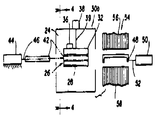
제1도는 본 발명에 따라 구성된 박판유리 압착굴곡 시스템의 개략적인 측면도.1 is a schematic side view of a thin glass press bending system constructed in accordance with the present invention.
제2도는 제1도의 2-2선을 따라 절단하여 나타낸 대략적인 단면도이며 일정하게 굴곡된 형상의 하부모울더가 제1 및 제2위치 사이에서 이동가능하며 상기 제1 및 제2위치는 모두 본 시스템의 가열된 주계내에 위치하고 있는 것을 나타낸 압착굴곡 시스템의 실시예.FIG. 2 is a schematic cross-sectional view taken along the line 2-2 of FIG. 1, in which a lower flexure of a constantly curved shape is movable between the first and second positions, both of which are seen An embodiment of a crimp bend system showing that it is located within the heated circumference of the system.
제3도는 제2도와 같은 방향으로 절단하여 나타낸 대략적인 단면도이며 가열된 주계의 내부와 외부로 이동가능한 일정하게 굴곡된 형상의 하부모울더가 있는 압착굴곡 시스템의 다른 실시예.3 is a schematic cross-sectional view cut in the same direction as in FIG. 2, with another embodiment of a compression bending system having a lower bend in a constant curved shape that is movable in and out of a heated column.
제4도는 제2도 또는 제3도의 4-4선의 방향을 따라 절단하여 나타낸 대략적인 도면이며 본 시스템의 상부모울드가 수평컨베이어에 근접하게 하향 이동하여 가열된 박판유리를 받아들어 압축굴곡 공정의 준비를 하는 방법을 나타내고 있다.4 is a schematic diagram cut along the direction of line 4-4 of FIG. 2 or FIG. 3, and the upper mold of the system is moved downward downward to the horizontal conveyor to receive the heated thin glass to prepare for the compression bending process. It shows how to do this.
제5도는 상부모울드가 상향 이동한 후에 제4도와 같은 방향으로 절단하여 나타낸 대략적인 도면이며 컨베이어 일측의 제1위치에서 상부모울드 아래의 제2위치로 이동한 후의 하부모울더를 나타내고 있다.FIG. 5 is a schematic view showing the upper mold cut in the same direction as FIG. 4 after the upper mold moves upward, and shows the lower mold after moving from the first position on one side of the conveyor to the second position under the upper mold.
제6도는 제5도와 같은 방향으로 절단하여 나타낸 대략적인 도면이며 상부모울드가 하부모울더에 대향하여 박판유리를 압착굴곡 하기 위하여 하향으로 이동한 후의 본 시스템을 나타내고 있다.FIG. 6 is an approximate drawing cut in the same direction as FIG. 5 and shows the present system after the upper mold has moved downward to squeeze the thin glass against the lower mold.
제7도는 제6도와 같은 방향으로 절단하여 대략적으로 나타낸 도면이며 상부모울드는 하부모울더와 분리되어 상향 이동하고 하부모울더는 제1위치로 복귀되어 이송모울드가 가상선으로 표시된 것와 같이 가열된 박판유리를 받기 위하여 상부모울드 아래로 이동한 후의 본 시스템을 나타내고 있다.FIG. 7 is a diagram schematically showing the same direction as in FIG. 6, wherein the upper mold is separated from the lower mold and moved upward, and the lower mold is returned to the first position so that the conveying mold is heated as shown by the virtual line. This system is shown after moving down the upper mold to receive the glass.
제8도는 전술한 제2도의 실시예와 같이 하부모울더가 가열된 주계내에 위치하고 있으나 전술한 실시예와 같은 일정하게 굴곡된 형상의 양끝에 이동가능하도록 된 모울드부분을 구비하고 있는 압착굴곡 시스템의 또 다른 실시예.FIG. 8 is a compression bending system of the compression bending system having a lower part located in a heated main body as in the embodiment of FIG. 2 described above, but having a mold portion that is movable at both ends of a uniformly curved shape as in the embodiment described above. Another embodiment.
제9도는 가열된 주계의 내부와 외부로 이동가능한 전술한 제3도의 실시예와 같고 일정하게 굴곡된 형상 대신에 이동가능한 모울드 부분들을 갖는 제8도의 실시예와 같은 하부모울드가 있는 압착굴곡 시스템의 또 다른 실시예.FIG. 9 is the same as the embodiment of FIG. 3 described above, which is movable inside and outside of the heated column, and has a lower mold as in the embodiment of FIG. 8 having movable mold portions instead of a constantly curved shape. Another embodiment.
제10도는 제8도 또는 제9도의 10-10선을 따라 절단하여 대략적으로 나타낸 도면이며 본 시스템의 상부 모울드가 수평컨베이어 측으로 하향이동하여 가열된 박판유리를 받아 굴곡 공정을 준비하는 방법을 나타냄.FIG. 10 is a diagram schematically showing the cut along lines 10-10 of FIG. 8 or 9, and shows how the upper mold of the system is moved downward to the horizontal conveyor to receive the heated sheet glass and prepare for the bending process.
제11도는 압착굴곡 공정을 위해 상부모울드 아래로 본 시스템의 하부모울더가 이동하고 상부모울드는 상향 이동한 후 제10도와 같은 방향으로 절단하여 대략적으로 도시한 도면.FIG. 11 is a diagram schematically illustrating the lower mold of the present system moved under the upper mold and the upper mold moved upward and then cut in the same direction as FIG. 10 for the compression bending process.
제12도는 상부모울드가 하향이동하여 하부모울더의 제1부분에 대향하여 박판유리를 압착굴곡한 후에 제11도와 같은 방향으로 절단하여 나타낸 대략적인 도면.FIG. 12 is an approximate view of the upper mold being moved downward to cut the thin glass against the first portion of the lower mold and cut in the same direction as in FIG.
제13도는 하부모울더의 한쌍의 제2부분이 상부모울드에 대향하여 박판유리가 완전히 압착굴곡 되도록 하부모울더의 제1부분에 대하여 이동한 후에 제12도와 같은 방향으로 절단하여 나타낸 도면.FIG. 13 is a view showing a cut in the same direction as in FIG. 12 after moving a pair of second portions of the lower moldor relative to the first portion of the lower mold so that the sheet glass is completely pressed against the upper mold.
제14도는 하부모울더가 상부모울드의 아래에서 완전히 이동하여 이송모울드가 가상선으로 나타낸 것같 같이 굴곡된 박판유리를 받기 위해 상부모울드 아래로 이동한 후에 제13도와 같은 방향을 따라 절단하여 나타낸 대략적인 도면.FIG. 14 shows an approximate cut-off along the direction shown in FIG. 13 after the lower mold moves completely below the upper mold so that the transfer mold is moved under the upper mold to receive the curved sheet glass as shown by the imaginary line. drawing.
제15도는 압착굴곡 시스템의 각 실시예에서 사용된 조절가능한 멈춤턱의 구조를 나타내고 있는 부분도.FIG. 15 is a partial view showing the structure of the adjustable stopper used in each embodiment of the compression bending system. FIG.
* 도면의 주요부분에 대한 부호의 설명* Explanation of symbols for main parts of the drawings
20 : 박판유리 압착굴곡 시스템 22 : 용광로(furnace)20: thin glass pressing and bending system 22: furnace (furnace)
24 : 가열실(heating chamber) 26 : 컨베이어(conveyor)24: heating chamber 26: conveyor
28 : 로울(roll)28 roll
30(30a, 30b, 30c, 30d) : 압착굴곡장소(press bending station)30 (30a, 30b, 30c, 30d): press bending station
31 : 압착굴곡기(press bending apparatus)31: press bending apparatus
32 : 상부모울드(upper mold) 34 : 굴곡된 하향면32: upper mold 34: curved downward surface
36, 40 : 가스제트펌프(gas jet pump) 38, 44, 50, 64 : 작동기(actuator)36, 40:
42 : 하부모울더(lower mold) 48 : 이송모울드(transfer mold)42: lower mold 48: transfer mold
54 : 냉각장소(quench station)54: quench station
56, 58 : 상하부블라스트헤드(upper and lower blast heads)56, 58: upper and lower blast heads
60 : 제1모울드부분(first mold portion)60: first mold portion
62 : 제2모울드부분(second mold portion)62: second mold portion
68 : 피봇(pivot) 70 : 멈춤턱(stop)68: pivot 70: stop
72 : 멈춤턱부재(stop member) 74 : 나선축(threaded shank)72: stop member 74: threaded shank
76 : 고정너트(lock nut)76: lock nut
본 발명은 굴곡된 박판유리를 강화하는데 있어서 특별한 유용성을 가진 박판유리 압착굴곡 시스템에 관한 것이다.The present invention relates to sheet glass press bending systems with particular utility in reinforcing curved sheet glass.
굴곡된 박판유리는 차량의 앞유리와 옆뒷 창문에 널리 사용되고 있다.Curved sheet glass is widely used in windshields and side windows of vehicles.
유리의 기계적인 강도를 높이기 위해서 굴곡된 박판유리는 빈번히 강화되는데, 이는 유리가 길고 날카로운 조각이 아닌 작고 무딘 조작으로 깨지게 하기 위해서이다.In order to increase the mechanical strength of the glass, curved sheet glass is often strengthened in order to break the glass by small, blunt operations rather than long, sharp pieces.
미국에서는, 굴곡된 박판강화 유리는 차량의 옆과 뒷창문에 사용되며 폴리비닐 뷰티랄(polyvinyl butyral)이 적층되어 어닐링(annealing)된 굴곡된 박판유리는 앞유리로서 사용한다.In the United States, curved thin tempered glass is used for the side and rear windows of vehicles, and curved thin glass, annealed with polyvinyl butyral laminated, is used as windshield.
다른 나라에서는 굴곡된 박판 강화 유리가 차량의 옆과 뒷유리창에는 물론 앞유리로서도 사용된다.In other countries, bent thin tempered glass is used on the side and rear windows of vehicles as well as windshields.
박판유리의 압착굴곡은 보완적으로 굴곡된 모울드 사이에서 가열된 박판유리를 압착하는 것에 의하여 행해지므로 가열된 박판유리는 굴곡된 모울드의 형상대로 굴곡된다.Pressed bending of the thin glass is performed by pressing the heated thin glass between complementary curved molds so that the heated thin glass is bent in the shape of the curved mold.
압착굴곡 시스템은 일반적으로 박판유리를 수평연장 방향으로 운반하면서 가열하기 위한 수평 컨베이어와 컨베이어 위의 굽힘 장소에 위치한 상부모울드를 구비하고 있다.Press-fit systems generally have a horizontal conveyor for heating and transporting sheet glass in the horizontal direction and an upper mold located at a bending place on the conveyor.
하부모울더는 컨베이어 아래에서 상방향으로 이동하여 가열된 각 박판유리를 위쪽의 상부모울드 쪽으로 끌어올려 압착굴곡 공정을 한 후에 하부모울드가 하방향으로 이동함에 따라 상부모울드는 진공상태를 형성하여 박판유리를 상기 상부모울드에 안전하게 지지한다.The lower molder moves upward from the bottom of the conveyor and pulls each heated sheet glass toward the upper mold upper part to perform the compression bending process. As the lower mold moves downward, the upper mold forms a vacuum state. Securely supports the upper mold.
그 후에 이상모울드는 상부모울드 아래로 수평이동하여 압착굴곡된 박판유리를 받아 이송한다.After that, the abnormal mold moves horizontally under the upper mold and receives the pressed glass sheet.
보통 이송모울드는 중심이 개방된 링(open center ring)형상이며, 압착굴곡된 박판유리를 템퍼링이 행해지는 냉각장소로 이송한다.Usually, the transfer mold has an open center ring shape and transfers the crimped thin sheet glass to a cooling place where tempering is performed.
상기한 바와 같은 형태의 압착굴곡 시스템은 가스단조로나 로울러 형태의 컨베이어에 사용할 수 있다.The compression bending system of the type described above can be used in a gas forging furnace or a roller type conveyor.
그러나, 박층의 압축가스막 상에서 박판유리를 운반하는 가스 단조로 컨베이어는 단조로에 하부모울더를 컨베이어 아래쪽으로 이동시키기 위한 홈(greove)이 있어, 가열된 박판유리가 하부모울드의 상향 이동을 위한 준비과정에서 하부모울드 표면으로 운반되어 압착굴곡 공정이 이루어지도록 한다.However, the gas forging furnace carrying thin glass on a thin compressed gas film conveyor has a groove in the forging furnace for moving the lower moldor below the conveyor, so that the heated thin glass is used for upward movement of the lower mold. In preparation, it is transported to the lower mold surface for the compression bending process.
마찬가지로, 이러한 형태의 압착굴곡 시스템은 로울들 사이의 공간으로 하부모울드를 움직이도록 하기 위하여 하부모울드는 분절되어야 하고, 박판유리의 둘레로 분절된 하부모울드가 모두 결합하여야 하므로, 압착은 불가능하다.Likewise, in this type of compression bending system, in order to move the lower mold into the space between the rolls, the lower mold must be segmented, and the lower mold segmented around the laminated glass must be combined so that the crimping is impossible.
미국특허 3,607,187호, 3,607,200호, 4,092,141호, 4,260,408호, 4,260,409호, 4,265,650호, 4,272,275호, 4,290,786호와 4,430,110호들은 상기한 압착굴곡 시스템과 같은 형태에 대해 기술하고 있다.U.S. Pat.
본 발명의 목적은 수평 컨베이어로부터 가열된 박판유리를 받아들여, 상기한 것과 같은 형태의 압착굴곡 시스템의 경우와 같이 수평 컨베이어를 통과하거나, 수평 컨베이어 안으로 하부모울드의 관입없이 압착굴곡을 수행하면서, 냉각을 위해 이송모울드가 도달하기 이전에 상하부모울더 사이에서 가열된 , 박판유리를 압착굴곡하는 개량된 박판유리 압착굴곡 시스템을 제공하는데 있다.An object of the present invention is to take a sheet of glass heated from a horizontal conveyor and cool it while passing through the horizontal conveyor as in the case of the crimp bending system of the type described above, or performing compression bending without penetration of the lower mold into the horizontal conveyor. To provide an improved sheet glass pressurization system for pressing and bending a heated sheet glass between upper and lower shafts before the transfer mold arrives.
상기한 바와 같은 목적을 수행하기 위해서, 본 발명의 박판유리 압착굴곡 시스템은 박판유리의 가열을 위한 가열된 주계가 있는 가열실을 구비한 용광로와 일반적으로 수평연장 방향으로 가열된 박판유리를 운반하기 위한 컨베이어를 구비하고 있다.In order to accomplish the above object, the sheet glass pressing and bending system of the present invention carries a blast furnace having a heating chamber with a heated column for heating the sheet glass and a sheet glass generally heated in the horizontal extension direction. It is equipped with a conveyor.
본 시스템의 상부모울드는 하향면이 굴곡되어 있고, 컨베이어 위에 위치하고 있다.The upper mold of the system is curved downward and located above the conveyor.
컨베이어 아래로부터 상향으로 분사되는 가스와 상부모울드에서의 진공형성은 상부모울드 아래의 컨베이어상에 있는 가열된 박판유리의 차동의 가스압을 공급하여 컨베이어 위에 위치한 상부모울드의 굴곡된 하향면에 대향하여 박판유리를 지지시킨다The gas blown upwards from below the conveyor and the vacuum formation in the upper mold supply the differential gas pressure of the heated laminated glass on the conveyor below the upper mold to face the curved downward surface of the upper mold located above the conveyor. Support
본 시스템의 하부모울드는 상향면이 굴곡되어 있고, 상부모울드에 인접한 제1위치에서 상부모울드 아래의 제2위치로 컨베이어와 같은 높이에서 수평운동을 하도록 장치되었고, 가열된 박판유리는 상부모울드에 의하여 지지된다.The lower mold of the system is curved upward and has a horizontal motion at the same height as the conveyor from the first position adjacent the upper mold to the second position below the upper mold, and the heated sheet glass is moved by the upper mold. Supported.
작동기는 상부모울드가 상하부모울드 사이에서 수직으로 이동하여 상하부모울드 사이에서 가열된 박판유리를 압착굴곡 할 수 있도록 한다.The actuator allows the upper mold to move vertically between the upper and lower molds to squeeze the heated sheet glass between the upper and lower molds.
본 시스템의 이송모울드는 상부모울드로부터 굴곡된 박판유리를 받아 굴곡된 형상대로 냉각하기 위해 수평이동을 한다.The transfer mold of this system receives the thin sheet glass curved from the upper mold and moves horizontally to cool the curved shape.
구체화된 압착굴곡 시스템의 한 실시예에서, 상부모울드는 컨베이어위에 위치해 가열된 주계내에 있고, 하부모울드는 제1 및 제2위치가 모두 가열된 주계내에 위치하므로, 하부모울드가 올린 온도를 유지하여 압착굴곡 공정 동안에 발생하는 유리의 파손을 감소시킨다.In one embodiment of the embodied compression bending system, the upper mold is located on the conveyor in a heated column, and the lower mold is located in a heated column in both the first and second positions, thus maintaining the temperature raised by the lower mold. Reduces the breakage of the glass that occurs during the bending process.
본 시스템의 이러한 실시예는 긴 압착시간이 요구되는 공정과 얇은 박판유리 공정에 이용할 때 매우 유용한데, 그 이유는 가열된 하부모울드는 박판유리에 결함을 발생시키지 않고, 굴곡시킬 수 있기 때문이다.This embodiment of the present system is very useful when used for processes requiring long pressing times and thin sheet glass processes because the heated lower mold can bend without causing defects in the sheet glass.
따라서 본 시스템의 이러한 실시예는 긴 압착시간이 요구되는 얇은 박판유리의 굴곡공정에 이용할 때 매우 유용하다.Therefore, this embodiment of the present system is very useful when used in the bending process of thin thin glass which requires a long pressing time.
압착굴곡 시스템의 다른 구체적인 실시예에서, 상부모울드는 컨베이어위의 가열된, 주계내에 위치하고 있으나, 하부모울드는 가열된 주계의 외부에 위치한 제1위치에서 냉각된다.In another specific embodiment of the compression bending system, the upper mold is located in a heated, perimeter above the conveyor, while the lower mold is cooled in a first position located outside of the heated perimeter.
압착굴곡 공정 동안에 하부모울드는 가열된 주계내에 있는 상부모울드 아래의 제2위치로 이동하는데, 냉각된 하부모울드는 박판유리에 결합이 발생하는 일없이 압착굴곡이 행해지도록 한다.During the press bending process, the lower mold moves to a second position below the upper mold in the heated column, where the cooled lower mold allows the pressing bend to occur without bonding to the laminated glass.
냉각된, 하부모울드를 사용하는 압착굴곡 시스템의 실시예는 압착공정이 길고, 얇은 박판유리 보다 문제점이 적은 압착굴곡 공정이 짧고, 두꺼운 압착굴곡를 냉각하면서 굴곡하는데, 이용할 때 특별한 유용성이 있다.Embodiments of a cooled, pressurized bending system using a lower mold have particular usefulness when used to cool and bend while cooling the thick crimp bending process, which has a long crimping process, a shorter crimping process that is less problematic than thin laminated glass.
상기한 두 가지 실시예의 압착굴곡 시스템들은 상부모울드에 대향하여 가열된 박판유리를 압착굴곡 하기 위해 상부모울드와 반대로 된 형상의 하부모울드를 구비하고 있다.The press bending systems of the two embodiments described above have a lower mold in the shape opposite to the upper mold for pressing bending the heated sheet glass against the upper mold.
또한 일정한 모양의 하부모울드가 있는 각 실시예의 냉각장소는 제1위치에 있는 하부모울드의 위치로부터 컨베이어와 상부모울드의 맞은 편에 위치하고 있다.In addition, the cooling station of each embodiment with a constant lower mold is located opposite the conveyor and upper mold from the position of the lower mold in the first position.
이송링은 냉각된 하부모울더를 구비한 본 시스템의 발전된 구체적인 실시예에서 하부모울드는 각자에 대하여 이동가능한 제1 및 제2모울드 부분을 구비한 또 다른 형태를 나타내고 있다.The conveying ring represents another form with the first and second mold portions movable relative to each other in the specific embodiment of the present system with the cooled lower molder.
초기에 하부모울드의 제1모울드 부분은 상부모울드에 대향하여, 가열된 박판유리를 압착해 초기 압착굴곡을 수행한다.Initially, the first mold portion of the lower mold opposes the upper mold to squeeze the heated thin glass to perform initial compression bending.
뒤이어, 하부모울드의 작동기는 제1모울드 부분에 대하여 하부모울드의 제2모울드 부분을 움직여 상부모울드에 대향하여 가열된 박판유리가 완전히 압착굴곡 되도록 한다.Subsequently, the actuator of the lower mold moves the second mold portion of the lower mold relative to the first mold portion so that the heated sheet glass is completely pressed against the upper mold.
여기서 나타낸 구체적인 실시예에서, 한쌍의 제2모울드 부분은 제1모울드 부분의 양끝에 위치하여 제1모울드 부분이 초기 압착굴곡을 한 후에 뒤이어 제1모울드 부분에 대하여 회동하여 압착굴곡을 한다.In the specific embodiment shown here, the pair of second mold portions are located at both ends of the first mold portion so that the first mold portion undergoes initial compression bend followed by rotational compression to the first mold portion.
개개의 제2모울드 부분을 움직이는 작동기는 가능한 한 가열된 주계의 외부에 위치하고, 상기 가열된 주계의 내부로 연장된 연결부를 가져 하부모울드를 제어하게 하는 것이 좋다.The actuators that move the individual second mold portions are preferably located outside of the heated column and have a connection extending into the heated column to control the lower mold.
일정한 모양의 하부모울드가 있는 구체적인 실시예에서와 같이, 제1 및 제2모울드 부분이 있는 하부모울드를 구비한 압착굴곡 시스템의 실시예도 템퍼링하기 위한 냉각장소를 구비하고 있다.As in the specific embodiment with the lower mold of a certain shape, the embodiment of the compression bending system having the lower mold with the first and second mold portions also has a cooling place for tempering.
마찬가지로, 냉각장소는 가급적이면 제1위치에 있는 하부모울드로부터 컨베이어와 상부모울드의 맞은 편에 위치하여 이송모울드가 상부모울드로부터 굴곡된 박판유리를 받아 하부모울드가 제1위치에 있는 동안 하부모울드와 직선방향으로 떨어진 냉각 장소로 이송는다.Similarly, the cooling station is preferably located opposite the conveyor and the upper mold from the lower mold in the first position so that the transfer mold receives the laminated glass bent from the upper mold, while the lower mold is in the first position. To a cooling location away from the
또한 조정가능한 멈춤턱은 가급적이면 압착굴곡 하는 동안 상하부모울드가 서로를 향한 움직임을 제한할 수 있도록 하는 것이 좋다.Also, the adjustable stop should preferably allow the upper and lower molds to limit movement towards each other during compression bending.
게다가, 서로에 대하여 움직일 수 있는 제1 및 제2모울드 부분을 가진 구체적인 실시예에서, 제1모울드 부분에 대하여 제2모울드 부분을 움직이는 작동기는 뒤이은 굴록 공정 동안에 최상의 결과를 얻기 위하여 제1모울드 부분에 대한 제2모울드 부분의 움직임을 제어할 수 있다.In addition, in a specific embodiment with first and second mold portions movable relative to each other, the actuator moving the second mold portion relative to the first mold portion may be used to obtain the best result during the subsequent rolling process. It is possible to control the movement of the second mold portion with respect to.
가장 바람직한 압착굴곡 시스템은 하향면이 굴곡된 상부모울드와 상부모울드의 굴곡된 하향면에 진공상태를 형성하여 얼마간의 차동 가스압을 제공함으로써, 컨베이어로부터 가열된 박판유리를 받아 초기에 지지하도록 상부모울드에 가스제트펌프를 구비하고 있다.The most desirable crimping system is to create a vacuum in the upper and the lower downwardly curved upper molds to provide some differential gas pressure, thereby receiving the heated sheet glass from the conveyor and initially supporting the upper mold. A gas jet pump is provided.
앞에서 언급한 바와 같이, 컨베이어 아래에 위치한 가스제트펌프에서 상향으로 분사되는 가스는 상부모울드의 가스제트펌프와 협력하여 상부모울드가 컨베이어로부터 가열된 박판유리를 받아 지지하도록 한다.As mentioned earlier, the gas injected upwards from the gas jet pump located below the conveyor cooperates with the gas jet pump of the upper mold so that the upper mold receives the laminated sheet glass from the conveyor.
상부모울드의 가스제트펌프 제어기는 진공의 정도를 조절하여 가열된 박판유리에 발생하는 결함을 감소시킨다.A gas jet pump controller in the upper mold adjusts the degree of vacuum to reduce defects in the heated sheet glass.
상기한 상부모울드의 가스제트펌프의 제어기는 (a) 초기에 컨베이어에서 상부모울드로 가열된 박판유리를 끌어올리는 동안에 진공상태를 형성하고, (b) 그후에, 진공도를 감소시켜 상부모울드에 대향하여 지지된 박판유리에 결함이 발생하는 것을 방지하고, (c) 뒤이어, 필요하다면 진공도를 더욱 조절하여 상하부모울드 사이에서 박판유리의 압착굴곡이 행해지는 동안에 압착굴곡이 행해짐에 따라 박판유리에 발생하는 변형을 방지하면서 압착굴곡 공정을 용이하게 할 수 있게 하고, (d) 마지막으로, 상부모울드 압력가스를 분사하여 굴곡된 박판유리를 상부모울드로부터 이탈시키는 순으로 작동된다.The controller of the gas jet pump of the upper mold establishes a vacuum state during (a) initially lifting the laminated glass heated from the conveyor to the upper mold, and (b) thereafter, reducing the degree of vacuum to support the upper mold. To prevent defects in the laminated glass, and (c) further adjusting the degree of vacuum, if necessary, so as to prevent deformation occurring in the laminated glass as it is pressed during the bending of the thin glass between the upper and lower molds. It is possible to facilitate the compression bending process while preventing, and (d) finally, the upper mold pressure gas is injected to remove the bent thin glass from the upper mold.
또한 가장 바람직한 압착굴곡 시스템은 전술한 바와 같이 하부모울드가 제1위치에서 상부모울드 아래의 제2위치로 이동한 후에 하부모울드에 대향하여 가열된 박판유리를 압착굴곡하도록 상부모울드를 하향으로 이동시키기 위한 작동기를 구비하고 있다. 하부모울드의 작동기는 하부모울드가 제1 및 제2위치 사이에서 이동하도록 한다.The most preferred crimping system is also for moving the upper mold downward to squeeze the heated sheet glass against the lower mold after moving the lower mold from the first position to the second position below the upper mold as described above. It is equipped with an actuator. The actuator of the lower mold causes the lower mold to move between the first and second positions.
마찬가지로, 이송모울드의 작동기는 초기에 이송모울드를 상부모울드의 아래로 이동시켜 굴곡된 박판유리를 받도록 한 후에 굴곡된 박판유리를 냉각하기 위해서 상부모울드로부터 떨어지도록 한다.Likewise, the actuator of the transfer mold initially moves the transfer mold down the upper mold to receive the curved laminated glass and then away from the upper mold to cool the curved laminated glass.
이송모울드의 작동기는 이송모울드를 상부모울드와 떨어진 곳으로 이동시켜 템퍼링하며 냉각하는 연합냉각 장소의 상하부블라스트헤드 사이에 위치시킨다.The actuator of the transfer mold is located between the upper and lower blast heads of the combined cooling place where the transfer mold is moved away from the upper mold and tempered and cooled.
본 발명의 목적, 장점 및 잇점들은 아래의 본 발명을 실행하기 위한 가장 좋은 방법의 상세한 설명으로부터 점차 명백해질 것이다.The objects, advantages and advantages of the present invention will become increasingly apparent from the following detailed description of the best method for carrying out the present invention.
제1도에 도시된 바와 같이 본 발명에 따라 구성된 박판유리 압착굴곡 시스템(20)은 박판유리를 가열하기 위해 가열된 공기가 순환하는 가열실(24)이 있는 용광로(22)를 구비하고 있다.As shown in FIG. 1, the thin
본 시스템의 컨베이어(26)는 가열된 박판유리를 일반적으로 수평연장 방향으로 운반하며, 컨베이어(26)는 미국특허 제3,806,312호, 3,934,970호, 3,947,242호 및 3,994,711에서 기술되고 있는 것과 같은 방법으로 마찰 구동되는 로울(28)들을 구비한 로울러 형태의 것을 사용하는 것이 좋다.The
본 시스템(20)의 압착굴곡 장소(30)에는 이후에 더 자세히 설명되는 바와 같이 본 발명에 따라 컨베이어(26)으로부터 가열된 박판유리를 받아 압착굴곡시키는 압착굴곡기(31)가 있다.In the
제2도 및 제3도를 참조하면 구체화된 두 굴곡장소(30a) 및 (30b)가 각기 설명되고 있으며, 그 내부에는 컨베이어(26)위에 위치하고, 제4도와 같이 굴곡된 표면(34)을 가진 상부모울드(32)가 있다.Referring to FIGS. 2 and 3, two specific bending places 30a and 30b are described, respectively, which are located on the
미국특허 제4,222,763호에서 나타내고 있는 것과 같은 형태의 가스제트펌프(36)는 차동가스 압력을 상부모울드(32) 아래의 컨베이어(26)상에 있는 가열된 박판유리에 공급하여 미국특허 제4,282,026호에 나타낸 것과 같은 방법으로 컨베이어위에 위치한 상부모울드의 하향굴곡면에 대향하여 박판유리가 지지될 수 있도록 한다.A
전형적인 공기실린더 형태의 작동기(38)는 상부모울드(32)를 수직으로 이동시키기 위한 연결부(39)를 가지고 있어, 제4도에 나타내고 있는 바와 같이 초기에 컨베이어(26)에 근접하게 상부모울드(32)를 하향 이동시켜, 컨베이어로부터 박판유리(G)로 초기에 용이하게 끌어 올려 가스제트펌프(36)에 의하여 진공상태가 형성되는 상부모울드 표면(34)과 결착하도록 한다.A typical air
미국특허 제4,204,854호에서 설명하고 있는 것과 같은 형태의 가스제트펌프(40)들은 위쪽의 컨베이어 로울(28) 사이로 가스를 상향분사하여, 차동가스 압력을 공급하여 진공상태를 형성하는 가스제트펌프(36)를 도와 초기에 가열된 박판유리가 상부모울드의 굴곡면(34)에 대향하여 지지될 수 있도록 한다.Gas jet pumps 40 of the type described in US Pat. No. 4,204,854 are gas jet pumps 36 which spray the gas upward between the upper conveyor rolls 28 to supply a differential gas pressure to form a vacuum state. Help the initially heated sheet glass to be supported against the
그 때 작동기(38)는 상부모울드(32)에 지지된 박판유리와 함께 상기 상부모울드(32)를 컨베이어(26)와 일정한 간격을 갖는 제5도의 위치로 상향이동시켜 연속 압착굴곡 공정의 준비를 한다.At this time, the
제2도 및 제3도에서 각기 구체화된 굴곡장소(30a) 및 (30b)에는 제5도에서 나타내고 있는 것과 같은 상향굴곡면을 가진 하부모울드(42)가 있다.In the bending places 30a and 30b respectively embodied in FIGS. 2 and 3, there is a
하부모울드(42)는 컨베이어(26)위의 높이에서 수평운동을 하며, 연결부(46)를 통하여 작동기(44)의 조작에 따라 수평으로 움직인다.The
작동기(44)는 하부모울드(42)가 실선으로 표시된 것과 같이 컨베이어(26) 일측의 상부모울드(32)와 인접된, 제1위치와 제5도에 도시된, 바와같이 상부모울드(32)에 가열되어 지지된 박판유리 아래에 가상선으로 표시된 상부모울드(32) 아래의 제2위치 사이에서 이동하도록 한다.The
제5도 및 제6도를 참고하면 상하부모울드(32) 및 (42) 사이에서 상대적인 수직운동을 제공하기 위한 상부모울드 작동기(38)는 상부모울드를 하향이동시켜, 상하부모울드(32) 및 (42)의 굴곡면들 사이에서 가열된 박판유리를 굴곡시킨다.5 and 6, the
그 후, 상부모울드(32)는 작동기(38)에 의하여 상향이동되어, 제7도와 같이 위치하고, 하부모울드(42)는 제2도 및 제3도에서 실선으로 도시된 제1위치로 복귀된다.Thereafter, the
제2도 및 제3도에서 나타낸 굴곡장소(30a) 및 (30b)의 각 구체화된, 이송모울드(48)는 연결부(52)에 의하여 작동기(50)와 상호 접속된다.Each embodiment of the transfer places 48 of the bends 30a and 30b shown in FIGS. 2 and 3 is interconnected with the
상기 이송모울드(48)는 굴곡된, 박판유리의 모양과 그 형태가 일치하며, 제7에서 나타내고 있는 바와 같이 상승된 상부모울드(32)와 컨베이어(26)사이에 위치하여 가상선으로 표시된 것과 같이 상부모울드(32)로부터 굴곡된 박판유리를 받아 들인다.The
그 후에 작동기(50)는 이송모울드(48)를 상부모울드(32) 아래로부터 수평으로 이동시켜 냉각시키는데, 이것은 이후에 더욱 자세히 설명되어질 것이다.The
상기한 바와 같이, 본 발명의 굴곡장소에서 행해지는 압착굴곡은 종래의 이러한 압착굴곡 시스템에서 나타나듯이 하부모울드가 컨베이어를 통과하는 관입없이, 컨베이어상의 상하부모울드(32) 및 (42) 사이에서 행해진다.As described above, the pressing bend in the bending place of the present invention is performed between the upper and
그러므로, 컨베이어가 가스 단조로 형태라면, 종래의 상하부모울드 형태인 가스단조로 굴곡시스템과 같이 굴곡된 박판유리의 모양과 일치하게 단조로에 홈을 만들 필요가 없다.Therefore, if the conveyor is in the form of gas forging, there is no need to make grooves in the forging furnace consistent with the shape of the sheet glass bent like the bending system of gas forging in the conventional upper and lower mold form.
마찬가지로, 앞서 설명한 바와 같이 컨베이어(26)가 로울러 컨베이어라면, 종래의 상하부모울드 형태인 로울러 컨베이어 압착굴곡 시스템과 같이 하부모울드를 분할링 형태로 만들 필요가 없다.Similarly, if the
게다가 상하부모울드(32) 및 (42)는 상부모울드가 가열된 박판유리를 받아들이기 전에 컨베이어에 관계없이 압착굴곡 공정을 수행하는데 요구되는 결착의 정도를 제공할 수 있도록 구성할 수 있다.In addition, the upper and
제2도에서 나타내고 있는 바와 같이 굴곡 장소(30a)에는 상부모울드(32)가 있으며, 상기 상부모울드(32)는 컨베이어(26)위의 위치에서 가열된 주계내에 위치하도록 가열실(24)내에 위치하고 있다.As shown in FIG. 2, there is an
또한, 하부모울드(42)는 가열실(24)내에 위치하여 실선과 가상선으로 각기 표시된 것같 같이 제1 및 제2위치에서 가열된 주계내에 위치한다.In addition, the
가열된 주계내에 위치한 하부모울드(42)의 연속적인 위치고정은 하부모울드가 계속 가열될 수 있도록 하고, 얇은 박판유리를 사용할 때나, 긴 압착공정시 압착굴곡 공정 동안에 유리에 발생하는 결함을 감소시키는데, 매우 유용하다.Continuous positioning of the
또한 상대적으로 가열된 하부모울드(42)는 이후에 더 자세히 설명되는 바와 같이 뒤이어, 강화되는 것을 방지하여 박판유리에 홈이 발생되는 것을 막는다.The relatively heated
제3도에서 나타내고 있는 바와 같이, 굴곡장소(30b)에는 상부모울드(32)가 있으며, 상기 상부모울드(32)는 컨베이어(26)상의 위치에서 가열된 주계내에 위치하도록 가열실(24)내에 위치한다.As shown in FIG. 3, the bending place 30b has an
그러나 하부모울드(42)는 용광로 가열실(24)의 외부에 위치하고, 가열된 주계는 실선으로 표시된 것과 같이 제1위치에서 제공되어 각 압착굴곡 공정사이에 하부모울드가 냉각될 수 있도록 한다.However, the
작동기(44)는 하부모울드(42)를 용광로 가열실(24)안으로 이동시켜, 착굴곡이 행해지는 상부모울드(32) 아래의 제2위치에 오도록 한다.The
압착굴곡은 하부모울드(42)가 냉각된 상태에 있기 때문에 박판유리에 결함을 발생시키는 일 없이 행하여진다.The crimping bending is performed without causing a defect in the thin glass because the
굴곡장소(30b)는 두꺼운 박판유리를 굴곡시킬 때 사용하거나, 굴곡된 박판유리의 냉각과 결함이 있는 짧은 공정주기를 가질 때 사용할 때, 특히 유용성이 있으며, 공정주기가 길거나 얇은 박판유리를 굴곡시킬 때처럼 문제점이 많지 않다.The bending place 30b is particularly useful when bending thick thin glass, or when cooling the curved thin glass and having a short process cycle that is defective, and has long processing cycles or thin thin glass. There aren't many problems as usual.
상기와 같은 구체적인 실시예에서 용광로에는 과도한 열손실 없이 가열실의 내부와 밖으로 하부모울드의 출입을 허용하도록 하는 개폐가 가능한 입구를 만들 수 있다In a specific embodiment as described above, the inlet can be opened and closed to allow the lower mold to enter and exit the heating chamber without excessive heat loss.
상기한 설명으로 부터 압착굴곡 장소(30a)에 있는 가열된 하부모울드는 굴곡공정 동안에 유리에 발생하는 결함을 감소시킬 수 있는 반면에 압착굴곡장소(30b)에 있는 냉각된 하부모울드는 굴곡공정 동안에 유리에 발생하는 결함(marking)을 감소시킨다.From the above description, the heated lower mold at the crimp bend 30a can reduce the defects that occur in the glass during the bending process, while the cooled lower mold at the crimp bend 30b is glass during the bend process. Reduces markings that occur at
이러한 고찰은 어떤 특정한 압착굴곡 작업을 위해서 가장 유용성 있는 압착굴곡 시스템을 구체화하여 결정하기 위해서 반드시 필요하다.This consideration is necessary to specify and determine the compression bending system that is most useful for any particular compression bending operation.
제2도 및 제3도에서 도시하고 있는 두 실시예의 굴곡장소(30a) 및 (30b)의 하부모울드(42)는 앞에서 설명한 방법으로 상부모울드(32)에 대향하여 압착굴곡을 수행하기 위해서 제5도와 같은 일정한 곡면모양을 이루고 있다.The
하부모울드(42)의 일정한 곡면모양은 이후에 설명되는 다른 복작한 모양으로 이루어진 하부모울드의 더욱 복잡한 굴곡과 비교하여 볼 때 복잡하지 않은 것은 압착하여 간단히 굴곡하는데 사용된다.The constant curved shape of the
제2도 및 제3도에서 보여주고 있는 바와 같이 압착굴곡장소(30a) 및 (30b)는 연결부(52)를 작동기(50)의 추진력에 의하여 이송모울드(48)가 굴곡된 박판유리를 이동시켜 강화하기 위한 냉각장소(54)를 구비하고 있다.As shown in FIG. 2 and FIG. 3, the compression bending places 30a and 30b move the connecting
이러한 형태의 냉각장소(54)는 미국특허 4,470,838에 나타나 있으며, 상기 냉각장소(54)는 강화하기 위해 냉각가스를 공급하는 상하부블라스트헤드(56) 및 (58)을 구비하고 있다.This type of cooling
이와 관련하여, 이송모울드(48)는 유리의 상, 하부 표면에 모두 냉각가스를 공급하기 위하여 굴곡된 박판유리의 둘레모양과 같은 중심이 개방된 링모양을 하고 있다.In this regard, the
제2도 및 제3도에서 도시된 굴곡장소(30a) 및 (30b)의 냉각장소(54)는 제1위치에 있는 하부모울드(42)와 같이 컨베이어(26)와 상부모울드(32)의 맞은편에 위치한다.The cooling
그러므로, 하부모울드(42)와 이송모울드(48)는 앞서 설명한 바와 같이 압착굴곡 공정 동안에 상부모울드(32) 아래의 위치에서 서로 반대방향으로 움직인다.Therefore, the
컨베이어(26)와 상부모울드(32)에 대하여 하부모울드(42)와 이송모울드(48)는 다른 방법으로 본 발명의 폭넓은 응용과 일치하게 할 수 있는 반면에 상부모울드(32)와 컨베이어(26)의 맞은편에 위치한 냉각장소(54)와 하부모울드(42)의 독특한 배열은 강화할 때 매우 특별한 유용성이 있다.With respect to the
제8도와 제9도를 참조하면 개량된 두개의 굴곡장소(30c) 및 (30d)를 나타내고 있으며, 이것은 앞서 설명한 제2도 및 제3도에서 보여준 굴곡장소(30a) 및 (30b)와 아래에서 설명하고 있는 것을 제외하고는 같다.Referring to FIG. 8 and FIG. 9, there are two improved bend places 30c and 30d, which are the same as the bend places 30a and 30b shown in FIGS. The same is true except for explaining.
제8도에서 도시하고 있는 바와 같이 굴곡장소(30c)에는 용광로 가열실(24)에 의하여 제공된 주계내 제1 및 제2위치사이는 움직이는 하부모울드(42)가 있으며, 앞서 설명한 굴곡장소(30a)는 하부모울드를 압착공정이 길거나, 얇은 박판유리를 굴곡시킬 때 요구되는 높은 온도로 유지한다.As shown in FIG. 8, the bending
제9도에 나타난 굴곡장소(30d)는 제3도에 나타낸 굴곡장소(30b)와 압착굴곡 공정사이에 냉각을 위해서 용광로 가열실(24)에 의한 가열주계의 외부로 하부모울드(42)가 이동한다는 점이 같으며, 이것은 앞서 설명한 바와 같이 압착공정이 짧거나, 박판유리가 두꺼울 때 요구되는 점이다.The
더 자세히 설명하면, 제8도 및 제9도에 유용된 예의 하부모울드(42)는 각기에 대하여 서로 이동 가능하도록 된, 제1 및 제2모울드부분(60, 62)을 구비하고 있다.In more detail, the
초기에 제1모울드 부분(60)은 압착굴곡 공정 동안에 상부모울드에 대향하여 가열된 박판유리를 압착한다.Initially, the
뒤이어, 제2모울드부분(62)과 연결부(66)을 통하여 연결된 작동기(64)는 제2모울드부분을 제1모울드부분에 대하여 이동시켜, 상부모울드에 대향하여 가열된 박판유리의 압착굴곡이 완전하게 되도록 한다.Subsequently, the
제8도 및 제9도에서 나타내고 있는 변형된 굴곡장소(30c) 및 (30d)는 앞서 설명한 것과 같은 방법으로 압착굴곡 공정을 개시한다.The modified bending places 30c and 30d shown in FIGS. 8 and 9 start the compression bending process in the same manner as described above.
제10도에 도시한 바와 같이 작동기(38)는 상부모울드(32)를 컨베이어(26)의 로울(28)과 근접하게 하향이동시켜, 하부가스제트펌프(40)에 의하여 상향으로 가스가 분사되고, 가스제트펌프(36)에 의하여 진공상태가 형성됨에 따라 박판유리(G)를 받아들여 상부모울드에 대향하여 박판유리가 지지되도록 한다.As shown in FIG. 10, the
또한 가스제프펌프(36, 40)들의 상호협력에 의하여 가열된 박판유리에 공급되는 차동가스 압력은 곡선모양의 상부모울드(32)에 대향하여 박판유리가 확실히 형성될 수 있도록 한다.In addition, the differential gas pressure supplied to the heated thin glass by the cooperation of the gas zep pumps 36 and 40 ensures that the thin glass is formed against the curved
제11도에 나타낸 바와 같이, 압착굴곡은 작동기(38)가 상부모울드(32)를 위쪽으로 이동시키고, 작동기 연결부(46)는 상부모울드 아래로 하부모울드를 이동시키고, 가열된 박판유리는 상부모울드에 지지되는 순서로 진행된다.As shown in FIG. 11, the crimp flexure causes the
하부모울드는 제1모울드부분(60)의 양끝에 위치된 한쌍의 제2모울드부분(62)을 구비한 구조로 되어 있고, 상기 제2모울드부분(62)은 작동기 연결부(66)의 조작에 따라 제1모울드부분(60)에 대하여 피봇(68) 둘레로 회동 가능하도록 되어 있다.The lower mold has a structure having a pair of
제8도 및 제9도에 나타낸 두 가지 실시예에서, 제1모울드부분(60)에 대하여 제2모울드부분(62)이 움직이도록 하는 작동기(64)는 열에 의하여 발생되는 제반문제를 피하기 위해 용광로가열실(24)에 의하여 만들어진 가열된 주계의 외부에 위치하고 있으며, 제2모울드부분(62)의 각 모울드부분은 연결부(66)에 의하여 전술한 바와 같이, 제2모울드부분(62)을 움직이는 작동기(64)와 연결되어 있다.In the two embodiments shown in FIGS. 8 and 9, the
제12도를 참조하면 작동기(38)는 가열된 박판유리가 지지된 상부모울드(32)를 하방향으로 움직여, 상부모울드와 하부모울드(42)의 제1부분(60)사이에서 초기 압착굴곡을 한다.Referring to FIG. 12, the
그 후에 작동기 연결부(66)는 제13도에 나타낸 바와 같이, 하부모울드(42)의 제2모울드부분(62)을 피봇(68) 둘레로 회동시켜 제1모울드부분(60)에 대하여 움직이도록 하여, 박판유리가 완전히 압착굴곡 되도록 한다.The
그 때 상부모울드(32)는 작동기(38)에 의하여 상향 이동하고, 하부모울드(42)는 상부모울드 아래로부터 외부로 이동하며, 이송모울드(48)는 제14도에 도시한 바와 같이 상부모울드 아래로 이동하여 가상선으로 나타낸 것처럼 가열된 박판유리를 받아 굴곡된 박판유리를 냉각하기 위해 운반한다.The
제8도 및 제9도에서 설명하고 있는 굴곡장소(30c) 및 (30d)는 이송모울드(48)가 전술한 것과 같은 방법으로 굴곡된, 박판유리를 템퍼링하기 위해 이동시키는 구체화된 냉각장소(54)가 있는 압착굴곡 시스템에 유용할 수 있다.The bending points 30c and 30d described in FIGS. 8 and 9 are embodied cooling points 54 which the
상하부 대향 블라스트헤드(56) 및 (58)을 구비하고 있는 냉각장소(54)는 그 사이에 이송링(48)이 위치해 전술한 바와 같이 박판유리의 양면에 냉각가스를 공급한다.The cooling
게다가, 냉각장소(54)는 제8도 및 제9도에서 실선으로 나타낸 것과 같이 제1위치에 있는 하부모울드(42)와 같이 상부모울드(32)와 컨베이어(26)의 반대편에 위치하고 있다.In addition, the cooling
그러므로, 하부모울드(42)와 이송모울드(48)는 압착굴곡 공정의 다른 단계에서 상부모울드 아래의 위치로 반대방향에서 이동을 한다.Therefore, the
제5, 6, 11, 12, 13 및 제15도에서 가장 잘 나타내고 있는 압착굴곡 시스템의 각 실시예는 상부 및 하부모울드(32) 및 (42)에 대하여 서로의 움직임을 제한하는 조정 가능한 멈춤턱을 구비하고 있다.Each embodiment of the compression bending system, best shown in FIGS. 5, 6, 11, 12, 13 and 15, has adjustable stops that limit each other's movement with respect to the upper and
제5도 및 제6도에서 나타내고 있는 조정 가능한 멈춤턱(70)은 일정한 곡률을 가진 하부모울드(42)상에 장착되어 있다.The
제11도에서 제13도까지에서 나타내고 있는 조정 가능한 멈춤턱은 하부모울드(42)의 제1 및 제2부분(60, 62)에 모두 장착되어 있다.The adjustable stop shown in FIGS. 11 to 13 is mounted to both the first and
각 실시예에서, 조정가능한 멈춤턱(70)은 굴곡공정을 방해하지 않도록 박판유리의 외곽에 위치하고 있다.In each embodiment, the
제15도에서 나타내고 있는 조정가능한 멈춤턱은 하부모울드(42)에 있는 나사구멍과 결합하도록 된 나선축(74)이 있는 멈춤부재(72)를 구비한 구조로 되어 있다.The adjustable stop shown in FIG. 15 has a structure with a stop member 72 having a spiral shaft 74 adapted to engage a screw hole in the
또한 나선축(74)과 결합하는 고정너트(76)는 멈춤부재(72)의 어떤 조절된 위치에서 하부모울드에 대향하여 나사관입되므로, 굴곡공정 동안에 하부모울드(42)와 상부모울드(32)가 일정한 간격으로 유지하도록 한다.In addition, since the fixing nut 76 coupled with the spiral shaft 74 is screwed into the lower mold at a controlled position of the stop member 72, the
조절가능한 멈춤턱(70)은 제5도 및 제6도에 나타낸, 하부모울드(42)와 제11도 내지 제13도에 나타낸 제1모울드 부분과 결합하여 굴곡공정 동안에 연합 작동기(38)가 박판유리에 과도한 힘을 가하는 것을 막는다.The
조정가능한 멈춤턱(70)은 제11도 내지 제13도에서 나타낸 바와 같이 하부모울드(42)의 한쌍의 제2모울드부분(62)과 결합하여 압착굴곡이 완전히 행해지는 동안에 제13도에서 나타낸 바와 같이 작동기 연결부(66)가 박판유리에 과도한 힘을 가하는 것을 방지한다.The
하부모울드(42)상에 자치된 조정가능한 멈춤턱(70)은 쉽게 조정할 수 있도록 하는 것이 좋으며, 상부모울드(32)에도 조정가능한 멈춤턱을 장치하는 것이 가능하다.The
게다가, 제11도 내지 제13도에 도시된 실시예에서, 하부모울드(42)의 제2모울드부분(62)을 움직이는 작동기(64, 제8도 및 제9도에 도시됨)는 제15도에 나타낸 바와 같이 조합된 멈춤턱(70)이 연동관계로 이동됨에 따라 소모되는 힘과 속도의 행태로 제1모울드 부분에 대한 제2모울드 부분의 움직임을 조절하기 위하여 가급적이며 조절할 수 있도록 하는 것이 좋다.In addition, in the embodiment shown in FIGS. 11 to 13, the actuator (shown in FIGS. 64, 8 and 9) for moving the
초기에 가스제트펌프(36)는 상향으로 가스를 분사하는 가스제프펌프(40)와 협력하여 컨베이어로부터 박판유리를 끌어올리기에 충분한 정도의 진공을 형성한다.Initially, the
그 후에 진공을 형성하는 상부모울드 표면(34)의 진공구멍들에 의하여 박판유리에 결함이 발생하는 것을 방지하기 위하여 진공도는 감소된다.The degree of vacuum is then reduced to prevent defects in the laminated glass by the vacuum holes in the
압착굴곡 공정 동안에 박판유리에 결합이 발생하는 것을 방지하기 위하여 진공도는 감소되거나 해제되는데, 이것은 굴곡공정을 더욱 용이하게 해준다.The degree of vacuum is reduced or released to prevent the bonding of thin glass during the crimping process, which makes the bending process easier.
불필요한 변형을 방지하며, 굴곡공정을 용이하게 하여 가장 좋은 결과를 얻기 위하여 굴곡공정 동안에 필요하다면 가스제트펌프(36)를 여러 단계로 조절할 수 있다.The
마지막으로, 가스제트펌프(36)는 상부모울드(32)로 압력가스를 분사해 굴곡된 박판유리가 중력과 압력가스에 의해 아래쪽에 있는 박판유리(48)에 떨어지도록 한다.Finally, the
앞에서 언급된 모든 특허의 내용은 본 압착굴곡 시스템의 내용에 의하여 구체화되었다.The contents of all the aforementioned patents have been embodied by the contents of the present compression bending system.
본 발명을 실행하기 위한 가장 좋은 방법을 구체적으로 살명하였으나, 본 발명과 관련된 유사한 기술분야에서는 아래의 특허 청구의 범위에 의하여 본 발명을 실시하기 위한 실시예와 설계가 여러가지로 변경될 수 있다는 것을 알게 될 것이다.Although the best method for carrying out the present invention has been specifically described, it will be appreciated that embodiments and designs for carrying out the present invention may be modified in various ways in accordance with the appended claims in the related art. will be.
Claims (16)
Applications Claiming Priority (2)
| Application Number | Priority Date | Filing Date | Title |
|---|---|---|---|
| US06/839,797 US4661141A (en) | 1986-03-14 | 1986-03-14 | Glass sheet press bending system |
| US839797 | 1986-03-14 |
Publications (2)
| Publication Number | Publication Date |
|---|---|
| KR870008803A KR870008803A (en) | 1987-10-21 |
| KR900005386B1 true KR900005386B1 (en) | 1990-07-28 |
Family
ID=25280644
Family Applications (1)
| Application Number | Title | Priority Date | Filing Date |
|---|---|---|---|
| KR1019870002097A KR900005386B1 (en) | 1986-03-14 | 1987-03-09 | Glass sheet press bending system |
Country Status (18)
| Country | Link |
|---|---|
| EP (1) | EP0237231B1 (en) |
| JP (1) | JPH0667766B2 (en) |
| KR (1) | KR900005386B1 (en) |
| CN (1) | CN1006885B (en) |
| AR (1) | AR240893A1 (en) |
| AT (1) | ATE58515T1 (en) |
| AU (1) | AU576443B2 (en) |
| BR (1) | BR8701175A (en) |
| CA (1) | CA1287215C (en) |
| DE (1) | DE3766271D1 (en) |
| ES (1) | ES2018541B3 (en) |
| FI (1) | FI82829C (en) |
| GR (1) | GR3001146T3 (en) |
| IE (1) | IE59803B1 (en) |
| IN (1) | IN169402B (en) |
| MX (1) | MX163755B (en) |
| NZ (1) | NZ219414A (en) |
| ZA (1) | ZA871530B (en) |
Families Citing this family (19)
| Publication number | Priority date | Publication date | Assignee | Title |
|---|---|---|---|---|
| DE3134933A1 (en) * | 1981-09-03 | 1983-03-31 | Hoechst Ag, 6230 Frankfurt | "UREA DERIVATIVES, METHOD FOR THE PRODUCTION THEREOF AND THE MEDICINES THEREOF AND THE USE THEREOF" |
| US4767437A (en) * | 1987-03-25 | 1988-08-30 | Ppg Industries, Inc. | Horizontal press bending using a splitting vacuum/pressure pickup |
| US5135557A (en) * | 1988-01-12 | 1992-08-04 | Saint-Gobain Vitrage | Process for bending and tempering glass sheets with lifting and gripping of glass sheets in a tempering station |
| DE68905703T2 (en) * | 1988-08-03 | 1993-07-08 | Nippon Sheet Glass Co Ltd | DEVICE FOR BENDING GLASS PANES. |
| JPH02296741A (en) * | 1989-05-11 | 1990-12-07 | Nippon Sheet Glass Co Ltd | Bend molding device for sheet glass |
| DE3929042C1 (en) * | 1989-09-01 | 1991-01-10 | Vegla Vereinigte Glaswerke Gmbh, 5100 Aachen, De | |
| ATE138898T1 (en) * | 1990-05-22 | 1996-06-15 | Glasstech Inc | VACUUM BENDING OF HEATED GLASS PANELS |
| DE4020708A1 (en) * | 1990-06-29 | 1992-01-09 | Ver Glaswerke Gmbh | METHOD AND DEVICE FOR PRODUCING CURVED AND TEMPERED GLASS PANELS |
| JP3139788B2 (en) * | 1991-09-04 | 2001-03-05 | 日本板硝子株式会社 | Sheet glass bending apparatus and bending method |
| JPH06256030A (en) * | 1993-03-02 | 1994-09-13 | Nippon Sheet Glass Co Ltd | Bending of sheet glass |
| DE19725189C1 (en) * | 1997-06-14 | 1998-11-26 | Sekurit Saint Gobain Deutsch | Device for bending glass sheets |
| KR100702255B1 (en) * | 2006-09-12 | 2007-04-03 | (주)한국나노글라스 | Tempered glass grinding apparatus of display window |
| EP2412682B1 (en) | 2010-07-29 | 2019-01-23 | Saint-Gobain Glass France | Method for bending glass panes |
| US20150218030A1 (en) * | 2014-02-06 | 2015-08-06 | Glasstech, Inc. | Forming station and method for forming a hot glass sheet with transverse curvature |
| PE20180761A1 (en) * | 2015-08-18 | 2018-05-03 | Saint Gobain | GLASS CURVING APPARATUS AND METHOD FOR CURVING GLASS USING A FAN |
| CN106116123B (en) * | 2016-06-21 | 2019-03-05 | 广东富山玻璃机械有限公司 | A kind of tempered glass of automobile production line |
| EP3661880A1 (en) * | 2017-07-31 | 2020-06-10 | Saint-Gobain Glass France | Method and device for bending panes |
| PL236771B1 (en) * | 2018-08-08 | 2021-02-22 | Pilkington Automotive Poland Spolka Z Ograniczona Odpowiedzialnoscia | Glass bending press |
| CN114248422B (en) * | 2021-12-03 | 2023-04-21 | 中国电子科技集团公司第二十九研究所 | Bending and shaping tool and method for RT/Duriod board |
Family Cites Families (10)
| Publication number | Priority date | Publication date | Assignee | Title |
|---|---|---|---|---|
| US3468645A (en) * | 1966-05-09 | 1969-09-23 | Permaglass | Method and apparatus for shaping glass sheets supported on a gas support bed |
| FR2085464B1 (en) * | 1970-04-23 | 1974-08-09 | Saint Gobain Pont A Mousson | |
| US3682613A (en) * | 1970-10-15 | 1972-08-08 | Ppg Industries Inc | Apparatus for press bending glass sheets |
| US4204854A (en) * | 1978-05-01 | 1980-05-27 | Mcmaster Harold | Apparatus and method for bending glass sheets |
| US4229200A (en) * | 1979-06-01 | 1980-10-21 | Ppg Industries, Inc. | Drop forming glass sheets with auxiliary shaping means |
| US4297118A (en) * | 1980-03-18 | 1981-10-27 | Ppg Industries, Inc. | Controlling overheating of vacuum mold used to shape glass sheets |
| DE3407173C1 (en) * | 1984-02-28 | 1985-01-03 | Mannesmann AG, 4000 Düsseldorf | Plant for the production of strongly curved glass panes |
| US4575390A (en) * | 1984-11-23 | 1986-03-11 | Glasstech, Inc. | Apparatus for forming glass sheets |
| JPS62182124A (en) * | 1986-02-03 | 1987-08-10 | Nippon Sheet Glass Co Ltd | Forming apparatus having mold changing device for flat glass |
| JPS6440773A (en) * | 1987-08-05 | 1989-02-13 | Koganei Ltd | Pressure control valve |
-
1987
- 1987-02-23 IE IE46087A patent/IE59803B1/en not_active IP Right Cessation
- 1987-02-24 IN IN128/MAS/87A patent/IN169402B/en unknown
- 1987-02-25 AU AU69242/87A patent/AU576443B2/en not_active Expired
- 1987-02-25 AT AT87301629T patent/ATE58515T1/en not_active IP Right Cessation
- 1987-02-25 DE DE8787301629T patent/DE3766271D1/en not_active Expired - Lifetime
- 1987-02-25 EP EP87301629A patent/EP0237231B1/en not_active Expired - Lifetime
- 1987-02-25 ES ES87301629T patent/ES2018541B3/en not_active Expired - Lifetime
- 1987-02-26 NZ NZ219414A patent/NZ219414A/en unknown
- 1987-03-02 AR AR306999A patent/AR240893A1/en active
- 1987-03-03 ZA ZA871530A patent/ZA871530B/en unknown
- 1987-03-09 KR KR1019870002097A patent/KR900005386B1/en not_active IP Right Cessation
- 1987-03-11 MX MX5531A patent/MX163755B/en unknown
- 1987-03-13 FI FI871122A patent/FI82829C/en not_active IP Right Cessation
- 1987-03-13 CA CA000531968A patent/CA1287215C/en not_active Expired - Lifetime
- 1987-03-13 BR BR8701175A patent/BR8701175A/en not_active IP Right Cessation
- 1987-03-13 CN CN87101950A patent/CN1006885B/en not_active Expired
- 1987-03-13 JP JP62058683A patent/JPH0667766B2/en not_active Expired - Lifetime
-
1990
- 1990-11-30 GR GR90401011T patent/GR3001146T3/en unknown
Also Published As
| Publication number | Publication date |
|---|---|
| FI82829C (en) | 1991-04-25 |
| FI871122A (en) | 1987-09-15 |
| AR240893A2 (en) | 1991-03-27 |
| NZ219414A (en) | 1988-06-30 |
| AU576443B2 (en) | 1988-08-25 |
| CA1287215C (en) | 1991-08-06 |
| CN1006885B (en) | 1990-02-21 |
| ZA871530B (en) | 1987-10-28 |
| FI871122A0 (en) | 1987-03-13 |
| ES2018541B3 (en) | 1991-04-16 |
| FI82829B (en) | 1991-01-15 |
| ATE58515T1 (en) | 1990-12-15 |
| DE3766271D1 (en) | 1991-01-03 |
| JPH0667766B2 (en) | 1994-08-31 |
| IE870460L (en) | 1987-09-14 |
| AR240893A1 (en) | 1991-03-27 |
| BR8701175A (en) | 1988-01-19 |
| IE59803B1 (en) | 1994-04-06 |
| CN87101950A (en) | 1988-01-13 |
| GR3001146T3 (en) | 1992-06-25 |
| KR870008803A (en) | 1987-10-21 |
| IN169402B (en) | 1991-10-12 |
| AU6924287A (en) | 1987-09-17 |
| EP0237231A1 (en) | 1987-09-16 |
| MX163755B (en) | 1992-06-19 |
| JPS62270429A (en) | 1987-11-24 |
| EP0237231B1 (en) | 1990-11-22 |
Similar Documents
| Publication | Publication Date | Title |
|---|---|---|
| KR900005386B1 (en) | Glass sheet press bending system | |
| US4661141A (en) | Glass sheet press bending system | |
| KR0165128B1 (en) | Glass sheet forming utilizing lower full surface vacuum mold and upper ring mold | |
| KR900000753B1 (en) | Method and apparatus for forming glass sheets | |
| JP3867932B2 (en) | Method and apparatus for bending / strengthening glass sheet | |
| US5735922A (en) | Method of bending and tempering glass sheets | |
| CA1321069C (en) | Architectural glass bending system | |
| EP0885851B1 (en) | Apparatus and method for bending glass sheets | |
| US4285715A (en) | Cycle of mold movement while press bending glass sheets | |
| SK30695A3 (en) | Method of convex bending of glass and device for realization of this method | |
| EP1550639A1 (en) | Method for bending a glass sheet and apparatus therefor | |
| CA1120726A (en) | Apparatus and method for bending glass | |
| EP2580170B1 (en) | Method, station and system for press forming glass sheets | |
| US4609391A (en) | Method for forming glass sheets | |
| JPH0214293B2 (en) | ||
| US4883527A (en) | Glass sheet bending and tempering apparatus | |
| JPS5943427B2 (en) | Glass sheet forming method and device | |
| US4670036A (en) | Conveying, supporting and shaping glass sheets | |
| JPH035330A (en) | Method and apparatus for preparing tempered bulging glass for automobile | |
| US4571253A (en) | Press bending apparatus | |
| KR960013570B1 (en) | Method and apparatus for bending and tempering glass-sheets | |
| PL182069B1 (en) | Method of bending glass sheets | |
| HRP940865A2 (en) | Method and apparatus for bending and tempering by contact |
Legal Events
| Date | Code | Title | Description |
|---|---|---|---|
| A201 | Request for examination | ||
| E902 | Notification of reason for refusal | ||
| G160 | Decision to publish patent application | ||
| E701 | Decision to grant or registration of patent right | ||
| GRNT | Written decision to grant | ||
| FPAY | Annual fee payment |
Payment date: 20060630 Year of fee payment: 17 |
|
| EXPY | Expiration of term |