EP0442017B1 - Method of forming abrasion-resistant coating layer - Google Patents
Method of forming abrasion-resistant coating layer Download PDFInfo
- Publication number
- EP0442017B1 EP0442017B1 EP19900103062 EP90103062A EP0442017B1 EP 0442017 B1 EP0442017 B1 EP 0442017B1 EP 19900103062 EP19900103062 EP 19900103062 EP 90103062 A EP90103062 A EP 90103062A EP 0442017 B1 EP0442017 B1 EP 0442017B1
- Authority
- EP
- European Patent Office
- Prior art keywords
- cr2o3
- spray coating
- weight
- coating layer
- melting
- Prior art date
- Legal status (The legal status is an assumption and is not a legal conclusion. Google has not performed a legal analysis and makes no representation as to the accuracy of the status listed.)
- Expired - Lifetime
Links
- 239000011247 coating layer Substances 0.000 title claims description 71
- 238000000034 method Methods 0.000 title claims description 47
- 238000005299 abrasion Methods 0.000 title claims description 30
- QDOXWKRWXJOMAK-UHFFFAOYSA-N dichromium trioxide Chemical compound O=[Cr]O[Cr]=O QDOXWKRWXJOMAK-UHFFFAOYSA-N 0.000 claims description 130
- 238000005507 spraying Methods 0.000 claims description 66
- 239000000843 powder Substances 0.000 claims description 35
- 238000002844 melting Methods 0.000 claims description 32
- 230000008018 melting Effects 0.000 claims description 32
- 239000000463 material Substances 0.000 claims description 23
- 229910052750 molybdenum Inorganic materials 0.000 claims description 19
- 229910001182 Mo alloy Inorganic materials 0.000 claims description 18
- 239000000203 mixture Substances 0.000 claims description 16
- 239000004615 ingredient Substances 0.000 claims description 15
- 230000000694 effects Effects 0.000 claims description 10
- 239000010410 layer Substances 0.000 claims description 10
- 239000000047 product Substances 0.000 claims description 8
- 239000007921 spray Substances 0.000 claims description 8
- VYPSYNLAJGMNEJ-UHFFFAOYSA-N Silicium dioxide Chemical compound O=[Si]=O VYPSYNLAJGMNEJ-UHFFFAOYSA-N 0.000 claims description 6
- GWEVSGVZZGPLCZ-UHFFFAOYSA-N Titan oxide Chemical compound O=[Ti]=O GWEVSGVZZGPLCZ-UHFFFAOYSA-N 0.000 claims description 6
- 230000002542 deteriorative effect Effects 0.000 claims description 6
- 239000012535 impurity Substances 0.000 claims description 6
- 238000002156 mixing Methods 0.000 claims description 6
- 239000007858 starting material Substances 0.000 claims description 6
- 230000008021 deposition Effects 0.000 claims description 5
- 239000000654 additive Substances 0.000 claims description 4
- PNEYBMLMFCGWSK-UHFFFAOYSA-N aluminium oxide Inorganic materials [O-2].[O-2].[O-2].[Al+3].[Al+3] PNEYBMLMFCGWSK-UHFFFAOYSA-N 0.000 claims description 4
- 238000001816 cooling Methods 0.000 claims description 4
- 238000010298 pulverizing process Methods 0.000 claims description 4
- 229910052761 rare earth metal Inorganic materials 0.000 claims description 4
- ZOKXTWBITQBERF-UHFFFAOYSA-N Molybdenum Chemical compound [Mo] ZOKXTWBITQBERF-UHFFFAOYSA-N 0.000 claims description 3
- 229910052681 coesite Inorganic materials 0.000 claims description 3
- 229910052906 cristobalite Inorganic materials 0.000 claims description 3
- JEIPFZHSYJVQDO-UHFFFAOYSA-N iron(III) oxide Inorganic materials O=[Fe]O[Fe]=O JEIPFZHSYJVQDO-UHFFFAOYSA-N 0.000 claims description 3
- 239000011733 molybdenum Substances 0.000 claims description 3
- 239000000377 silicon dioxide Substances 0.000 claims description 3
- 235000012239 silicon dioxide Nutrition 0.000 claims description 3
- 229910052682 stishovite Inorganic materials 0.000 claims description 3
- 229910052905 tridymite Inorganic materials 0.000 claims description 3
- 230000000996 additive effect Effects 0.000 claims description 2
- 238000005275 alloying Methods 0.000 claims description 2
- 239000007795 chemical reaction product Substances 0.000 claims description 2
- 229910052593 corundum Inorganic materials 0.000 claims description 2
- 239000011261 inert gas Substances 0.000 claims description 2
- 238000004519 manufacturing process Methods 0.000 claims description 2
- 229910001845 yogo sapphire Inorganic materials 0.000 claims description 2
- 239000011246 composite particle Substances 0.000 claims 1
- 239000011369 resultant mixture Substances 0.000 claims 1
- 239000002131 composite material Substances 0.000 description 20
- 239000000758 substrate Substances 0.000 description 16
- 239000002245 particle Substances 0.000 description 11
- 239000000314 lubricant Substances 0.000 description 9
- 239000011159 matrix material Substances 0.000 description 8
- 238000012360 testing method Methods 0.000 description 8
- 229910052751 metal Inorganic materials 0.000 description 7
- 239000002184 metal Substances 0.000 description 7
- 230000000052 comparative effect Effects 0.000 description 6
- 239000000919 ceramic Substances 0.000 description 5
- 238000005260 corrosion Methods 0.000 description 5
- 230000007797 corrosion Effects 0.000 description 5
- 238000000576 coating method Methods 0.000 description 4
- 230000005496 eutectics Effects 0.000 description 4
- 230000003287 optical effect Effects 0.000 description 4
- 239000011248 coating agent Substances 0.000 description 3
- 238000010586 diagram Methods 0.000 description 3
- 229910052782 aluminium Inorganic materials 0.000 description 2
- 239000002826 coolant Substances 0.000 description 2
- 238000010891 electric arc Methods 0.000 description 2
- -1 for example Chemical compound 0.000 description 2
- 239000007789 gas Substances 0.000 description 2
- 230000005484 gravity Effects 0.000 description 2
- 238000000227 grinding Methods 0.000 description 2
- 238000010438 heat treatment Methods 0.000 description 2
- 229910052742 iron Inorganic materials 0.000 description 2
- 239000007788 liquid Substances 0.000 description 2
- 230000013011 mating Effects 0.000 description 2
- 230000003014 reinforcing effect Effects 0.000 description 2
- 230000009897 systematic effect Effects 0.000 description 2
- RYGMFSIKBFXOCR-UHFFFAOYSA-N Copper Chemical compound [Cu] RYGMFSIKBFXOCR-UHFFFAOYSA-N 0.000 description 1
- 229910052692 Dysprosium Inorganic materials 0.000 description 1
- 229910052691 Erbium Inorganic materials 0.000 description 1
- 229910052693 Europium Inorganic materials 0.000 description 1
- 229910052688 Gadolinium Inorganic materials 0.000 description 1
- 229910052689 Holmium Inorganic materials 0.000 description 1
- 229910052765 Lutetium Inorganic materials 0.000 description 1
- 229910052779 Neodymium Inorganic materials 0.000 description 1
- 229910052772 Samarium Inorganic materials 0.000 description 1
- 229910052775 Thulium Inorganic materials 0.000 description 1
- 238000002441 X-ray diffraction Methods 0.000 description 1
- 229910052769 Ytterbium Inorganic materials 0.000 description 1
- 238000004458 analytical method Methods 0.000 description 1
- 238000005524 ceramic coating Methods 0.000 description 1
- 238000006243 chemical reaction Methods 0.000 description 1
- 229910052804 chromium Inorganic materials 0.000 description 1
- 239000000470 constituent Substances 0.000 description 1
- 238000007796 conventional method Methods 0.000 description 1
- 229910052802 copper Inorganic materials 0.000 description 1
- 239000010949 copper Substances 0.000 description 1
- 230000007850 degeneration Effects 0.000 description 1
- 238000010894 electron beam technology Methods 0.000 description 1
- 238000004453 electron probe microanalysis Methods 0.000 description 1
- 239000002320 enamel (paints) Substances 0.000 description 1
- 238000002474 experimental method Methods 0.000 description 1
- 238000010030 laminating Methods 0.000 description 1
- 229910052746 lanthanum Inorganic materials 0.000 description 1
- 238000005259 measurement Methods 0.000 description 1
- 150000001247 metal acetylides Chemical class 0.000 description 1
- 150000002739 metals Chemical class 0.000 description 1
- 229910052759 nickel Inorganic materials 0.000 description 1
- 239000004482 other powder Substances 0.000 description 1
- 230000003647 oxidation Effects 0.000 description 1
- 238000007254 oxidation reaction Methods 0.000 description 1
- 238000005191 phase separation Methods 0.000 description 1
- 238000007747 plating Methods 0.000 description 1
- 238000013001 point bending Methods 0.000 description 1
- 230000001737 promoting effect Effects 0.000 description 1
- 238000007873 sieving Methods 0.000 description 1
- 238000009718 spray deposition Methods 0.000 description 1
- 239000000126 substance Substances 0.000 description 1
- 238000004381 surface treatment Methods 0.000 description 1
- 238000010998 test method Methods 0.000 description 1
- WFKWXMTUELFFGS-UHFFFAOYSA-N tungsten Chemical compound [W] WFKWXMTUELFFGS-UHFFFAOYSA-N 0.000 description 1
- 229910052721 tungsten Inorganic materials 0.000 description 1
- 239000010937 tungsten Substances 0.000 description 1
- 238000007740 vapor deposition Methods 0.000 description 1
- 238000003466 welding Methods 0.000 description 1
Images


Classifications
-
- C—CHEMISTRY; METALLURGY
- C23—COATING METALLIC MATERIAL; COATING MATERIAL WITH METALLIC MATERIAL; CHEMICAL SURFACE TREATMENT; DIFFUSION TREATMENT OF METALLIC MATERIAL; COATING BY VACUUM EVAPORATION, BY SPUTTERING, BY ION IMPLANTATION OR BY CHEMICAL VAPOUR DEPOSITION, IN GENERAL; INHIBITING CORROSION OF METALLIC MATERIAL OR INCRUSTATION IN GENERAL
- C23C—COATING METALLIC MATERIAL; COATING MATERIAL WITH METALLIC MATERIAL; SURFACE TREATMENT OF METALLIC MATERIAL BY DIFFUSION INTO THE SURFACE, BY CHEMICAL CONVERSION OR SUBSTITUTION; COATING BY VACUUM EVAPORATION, BY SPUTTERING, BY ION IMPLANTATION OR BY CHEMICAL VAPOUR DEPOSITION, IN GENERAL
- C23C4/00—Coating by spraying the coating material in the molten state, e.g. by flame, plasma or electric discharge
- C23C4/04—Coating by spraying the coating material in the molten state, e.g. by flame, plasma or electric discharge characterised by the coating material
- C23C4/06—Metallic material
Definitions
- the present invention concerns a method of forming an abrasion resistant coating layer and, more in particular, it relates to a method of forming a coating layer having high lubricant retainability and excellent abrasion resistance.
- spray coating process makes possible to form coating layer of various metals, ceramics or composite materials thereof, because the molten metal, ceramics, and others collide against the surface of substrate at a high speed and a coating layer is formed on the surface of members by the process. Then, by spray coating a metal, for instance, desirable property such as corrosion resistance, heat resistance and electroconductivity can be provided.
- the surface must not be excessively smooth to keep the scuffing resistance property. If the surfaces is extremely smooth, the lubricant retainability at the sliding surfaces is lowered tending to cause lack of the lubricant and led to scuffing.
- the abrasion resistance can be improved due to the high hardness of the coating layer.
- a member is a sliding member
- the sliding property is inevitably reduced since the roughness at the surface of the coating layer is high.
- ceramic coating layer of high hardness may possibly injure the mating material.
- the fracture toughness of the ceramics is low, the brittle fracture occurs on the friction surface, follows a problem that abrasion can not be reduced sufficiently.
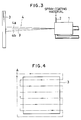
- a spray coating gun 1 as shown in Fig. 3 is usually employed and spray coating material is supplied from a spray coating material supply port 2 and jetted in a flame or plasma 4 onto the surface of a substrate 3 to form the coating layer.
- the spray coating gun 1 is moved relative to the plate surface of the substrate 3 as shown in Fig. 4.
- Fig. 4 shows a trace of a center of the working spray coating gun (center of the plasma) projected on the plate surface of the substrate 3.
- the spray coating gun is reciprocated leftward and lightward from a starting point A for spray coating and, simultaneously, displaced little by little downwardly at each of the turning points on both ends. Then, after reaching the lowermost end of the substrate 3, the gun is returned to the starting point A for spray coating.
- Such procedures of the spray coating gun are usually repeated by an appropriate number of cycles to form required coating thickness.
- an abrasion resistant coating layer excellent both in the lubricant retainability and the sliding property can be formed.
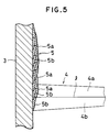
- a spray coating layer using a powder mixture of a Mo or Mo alloy powder and a Cr2O3 powder as the spray coating material there is the following problem.
- the spray coating layer 5 thus formed comprises the Cr2O3-enriched layer 5a and the Mo-enriched layer 5b stacked one above the other and it is impossible to form a Cr2O3-Mo composite material coating layer in which Mo and Cr2O3 are finely dispersed.
- Mo and Cr2O3 can be dispersed extremely finely. Accordingly, a powder obtained by cooling to solidify the molten mixture and then pulverizing them can provide Cr2O3-Mo composite material particles in which respective particles are finely dispersed therein.
- the spray coating layer formed by the method according to the present invention is a coating layer of composite material comprising Mo as high melting point metal and Cr2O3 as ceramics of high hardness. Accordingly, the coating layer is excellent having both of the high toughness of Mo and heat resistance, high hardness and chemical stability of Cr2O3. Great toughness and high hardness thus combined can remarkably improve the abrasion resistance of the coating layers.
- the coating layer formed in accordance with the present invention has a structure in which a Mo phase is dispersed into a Cr2O3 matrix phase.
- the Mo phase hardness lower than Cr2O3 is abraded to form a plurality of fine pits at the surface of the coating layer.
- the pits function as a retainer of the lubricant, remarkably improve the lubricant supply and improve the abrasion resistance at the surface of the member.
- An object of the present invention is to provide a method capable of preventing separate flying of Mo or Mo alloy particles and Cr2O3 particles during spray coating and forming a coating layer of Cr2O3-Mo composite material coating layer having satisfactory abrasion resistance and sliding property together.
- Another object of the present invention is to provide a method of forming a coating layer of Cr2O3-Mo composite material capable of greatly improving the endurance of sliding members, etc. using a lubricant.
- Fig. 1 is a systematic diagram illustrating a method of practicing the present invention.
- a Mo or Mo alloy powder, a Cr2O3 powder and, optionally, other powder are at first mixed at a predetermined ratio and the resultant powder mixture is melted.
- arc melting is suitable.
- Upon melting it is preferred to apply heating under an inert gas atmosphere such as of Ar gas for preventing degeneration of the starting material such as oxidation of Mo upon melting under heating.
- an inert gas atmosphere such as of Ar gas
- Melting may be conducted at any temperature so long as the powder mixture can be melted and, usually, it is conducted at a temperature higher than the melting point of Mo or Mo alloy. By the melting, the powder mixture is formed into a state where Mo, Cr2O3, etc. are finely dispersed and mixed to each other.
- solidified products obtained by cooling after melting the powder mixture constitute an ingot of Cr2O3-Mo series composite material in which Mo, Cr2O3, etc. are finely dispersed.
- the resultant ingot of Cr2O3-Mo system composite material is then pulverized and sieved using appropriate means.
- the ingot is coarsely pulverized by using a hammer mill, etc. and then finely pulverized by a ball mill, etc. and then sieved.
- the grain size is adjusted such that it is suitable to spray coating, that is, about from 1 to 100 ⁇ m, preferably, from 10 to 44 ⁇ m.
- the Cr2O3-Mo system composite material powder as the starting material, may be spray coated to the surface of a member and, subsequently, laser beams may be irradiated further to the surface of the spray-coated layer thus formed for promoting melting of the coating layer.
- Irradiation of laser beams is suitable to a case where the melting of starting material is insufficient but it also has an effect of increasing the density of the spray coating layer even in a case where sufficiently melted powder is spray coated. Further, it has an effect of melting also the mating interface between the coating layer and the substrate thereby increasing the bonding strength and enabling to form the coating layer to all kinds of substrates.
- coating layer can be formed to the surface of members of any kind of materials with no particular restriction. Further, the thickness of the coating layer formed can be varied optionally by changing conditions for spray coating such as a spray coating time.
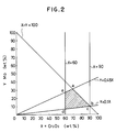
- content of other ingredients than Cr2O3 and Mo is defined as below 34% in view of the preferred range described above (60% of Cr2O3 and 6% (60 x 0.10) of Mo).
- ingredients other than Cr2O3 and Mo there can be mentioned, for example, the following ingredients (1) - (4).
- R2O3 type oxides R represents rare earth element
- R represents rare earth element
- La Nd, Sm, Eu, Gd, Dy, Ho, Er, Tm, Yb and Lu.
- the Mo alloy when a Mo alloy is used as the starting material, it is preferred that the Mo alloy contains not greater than 30% of Fe, not greater than 10% of Al, not greater than 10% of Ni, not greater than 15% of Cr, not greater than 10% of Co, not greater than 3% of C.
- Fe is inexpensive and capable of reducing the cost of the Mo alloy but, since excess Fe will deteriorate the abrasion resistance and the melting point of the coating layer, it is preferred that Fe is not greater than 30%, particularly, not greater than 20%.
- Al can refine the metal texture and improve the corrosion resistance thereof but, since excess amount of Al will reduce the corrosion resistance and lower the melting point of the coating layer, it is preferably not greater than 10%, more preferably, not greater than 7%.
- Ni is effective for reinforcing the substrate but excess amount of Ni tends to cause different textures. Accordingly, Ni is preferably not greater than 10% and, particularly, not greater than 7%.
- Cr improves the corrosion resistance of the substrate but it easily tends to form carbides and excess content thereof tends to deteriorate the toughness of the metal texture. Accordingly, Cr is preferably not greater than 15%, particularly preferably, not greater than 10%.
- Co has an effect of reinforcing the substrate but, since excess Co will lower the melting point of the substrate, it is preferably not greater than 10% and, particularly preferably, not greater than 7%.
- C has a function of improving the scuffing resistance and the abrasion resistance of the substrate but, since excess amount of C increases the deposition amount of the carbide and deteriorating the strength of the substrate itself, it is preferably not greater than 3%.
- the method of forming the abrasion resistance coating layer according to the present invention it is possible to easily form a coating layer of high performance comprising Cr2O3 and Mo finely dispersed therein having satisfactory lubricant-retainability, excellent both in abrasion resistance and scuffing resistance and also excellent in mechanical property onto the surface of substrates made of any kind of materials.
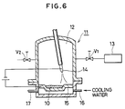
- a Cr2O3 powder and a Mo powder were mixed to obtain a powder mixture of a composition comprising 76%Cr2O3 - 24%Mo and a powder mixture 10 was melted in an arc melting furnace 11 shown in Fig. 6.
- a valve V1 was at first opened to evacuate the inside to 1.33 x 10 ⁇ 4 mbar (1 x 10 ⁇ 4 Torr) by means of a vacuum pump 13. Then, the valve V1 is closed and another valve V2 was opened to introduce an Ar gas at 99.99% purity to increase the pressure in a melting chamber 15,96 to 1010,8 mbar (12 to 760 Torr).
- a voltage was applied between a tungsten electrode (negative electrode) 14 and a water-cooled copper crucible (positive electrode) 15 in a melting chamber 12 (16 represents an inlet and 17 represents an exit of coolants) and arc discharge was conducted to melt the powder mixture 10 by the heat of the arc.
- the obtained solidified product was coarsely pulverized by using a hammer mill, finely pulverized in a ball mill using an alumina pot and alumina balls and then sieved to obtain a powder of a grain size of 10 to 44 ⁇ m.
- the cross section of the resultant particulate grains was observed by way of an optical microscope. It was confirmed that the respective grains were Cr2O3 - Mo composite material particles in which Mo was finely dispersed in the Cr2O3 matrix.
- the resultant Cr2O3-Mo composite material powder was plasma spray coated to the surface of a substrate made of SUS 430 to form a coating layer of 300 ⁇ m thickness.
- Spray coating device Low pressure plasma spray coating device Pressure of atmosphere (100 ⁇ 120 Torr) 133 ⁇ 159.6 mbar Amount of power supplied 1.5 kg/hr
- a coating layer was formed in the same procedures as those in Example 1 except for using a powder mixture of Cr2O3 - 24%Mo prepared by merely mixing a Cr2O3 powder and a Mo powder as the spray coating material.
- the coating layer had a laminated structure in which white Mo layers and gray Cr2O3 layers were alternately laminated with respect to the direction along the thickness of the coating layer.
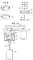
- Fig. 10 After grinding the surface of the resultant pin-type specimen (rotation side) 21 and the disc-type specimen (fixing side) 22 on the side of sliding movement, they were set so as to be applied with the rotational force R and vertical load W as shown in Fig. 9 and the abrasion amount was measured by using a device as shown in Fig. 10.
- Fig. 10 In Fig. 10, are shown a belt 23, a shaft 24, a motor 25, a coolant oil circulating pipe 26, a lubricant 27 and air cylinder 28.
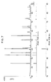
- the experiment conditions in this case are as shown in Table-2. Results are shown in Fig. 11.
- Test specimen was prepared in the same procedures as those in Example 2 except for using a powder mixture of Cr2O3 + 24%Mo only by mixing a Cr2O3 powder and a Mo powder.
- the resultant test specimen was measured for the abrasion amount in the same way as in Example 2. The results are shown in Fig. 11(a) and (b).
Landscapes
- Chemical & Material Sciences (AREA)
- Engineering & Computer Science (AREA)
- Physics & Mathematics (AREA)
- Plasma & Fusion (AREA)
- Chemical Kinetics & Catalysis (AREA)
- Materials Engineering (AREA)
- Mechanical Engineering (AREA)
- Metallurgy (AREA)
- Organic Chemistry (AREA)
- Coating By Spraying Or Casting (AREA)
- Manufacture Of Metal Powder And Suspensions Thereof (AREA)
Priority Applications (1)
| Application Number | Priority Date | Filing Date | Title |
|---|---|---|---|
| DE1990615801 DE69015801T2 (de) | 1990-02-16 | 1990-02-16 | Verfahren zur Herstellung einer verschleissfesten Oberflächenschicht. |
Applications Claiming Priority (1)
| Application Number | Priority Date | Filing Date | Title |
|---|---|---|---|
| JP63210095A JPH0261050A (ja) | 1988-08-24 | 1988-08-24 | 耐摩耗性被膜の形成方法 |
Publications (2)
| Publication Number | Publication Date |
|---|---|
| EP0442017A1 EP0442017A1 (en) | 1991-08-21 |
| EP0442017B1 true EP0442017B1 (en) | 1995-01-04 |
Family
ID=16583734
Family Applications (1)
| Application Number | Title | Priority Date | Filing Date |
|---|---|---|---|
| EP19900103062 Expired - Lifetime EP0442017B1 (en) | 1988-08-24 | 1990-02-16 | Method of forming abrasion-resistant coating layer |
Country Status (2)
| Country | Link |
|---|---|
| EP (1) | EP0442017B1 (enExample) |
| JP (1) | JPH0261050A (enExample) |
Families Citing this family (2)
| Publication number | Priority date | Publication date | Assignee | Title |
|---|---|---|---|---|
| JP5549834B2 (ja) * | 2009-04-30 | 2014-07-16 | 住友大阪セメント株式会社 | 溶射膜及びその製造方法 |
| DE102010038947A1 (de) * | 2010-08-05 | 2012-02-09 | Aktiebolaget Skf | Verbindungsanordnung und Verfahren zur Herstellung eines hülsenförmig ausgebildeten Verbindungselements |
Family Cites Families (2)
| Publication number | Priority date | Publication date | Assignee | Title |
|---|---|---|---|---|
| JPS6299449A (ja) * | 1985-10-25 | 1987-05-08 | Showa Denko Kk | クロムカ−バイト系溶射用粉末 |
| JPS6314851A (ja) * | 1986-07-03 | 1988-01-22 | Tech Res Assoc Highly Reliab Marine Propul Plant | 耐摩耗性被膜及びその形成方法 |
-
1988
- 1988-08-24 JP JP63210095A patent/JPH0261050A/ja active Granted
-
1990
- 1990-02-16 EP EP19900103062 patent/EP0442017B1/en not_active Expired - Lifetime
Also Published As
| Publication number | Publication date |
|---|---|
| JPH0261050A (ja) | 1990-03-01 |
| EP0442017A1 (en) | 1991-08-21 |
| JPH0327627B2 (enExample) | 1991-04-16 |
Similar Documents
| Publication | Publication Date | Title |
|---|---|---|
| EP1485220B1 (en) | Corrosion resistant powder and coating | |
| EP0505172B1 (en) | Wear-resistant copper-base alloy | |
| EP0224724B1 (en) | Amorphous alloy | |
| CA2161611C (en) | Hard composite material for tools | |
| US4507151A (en) | Coating material for the formation of abrasion-resistant and impact-resistant coatings on workpieces | |
| EP0620286B1 (en) | Ceramic-particle-dispersed metallic member, manufacturing method of same and use of same | |
| RU2296804C1 (ru) | Алюминиевый сплав для поверхностей, подвергающихся трибологическим нагрузкам | |
| EP1612292B1 (en) | Sputtering target and method for preparation thereof | |
| US4620872A (en) | Composite target material and process for producing the same | |
| EP0773202B1 (en) | Composite material and method of manufacturing the same | |
| Freitas et al. | Microstructural characterization and wear resistance of boride-reinforced steel coatings produced by Selective Laser Melting (SLM) | |
| JPS63109151A (ja) | 高硬度複合材およびその製造方法 | |
| EP1880036A2 (en) | Coating process for manufacture or reprocessing of sputter targets and x-ray anodes | |
| EP0344421B1 (en) | Burnt surface sintered alloy with and without a rigid surface film coating and process for producing the alloy | |
| US20130233706A1 (en) | Al-based alloy sputtering target and production method of same | |
| Gui et al. | Dry sliding wear behavior of plasma-sprayed aluminum hybrid composite coatings | |
| US4799977A (en) | Graded multiphase oxycarburized and oxycarbonitrided material systems | |
| US3257178A (en) | Coated metal article | |
| Zimogliadova et al. | Structural characterization of layers fabricated by non-vacuum electron beam cladding of Ni-Cr-Si-B self-fluxing alloy with additions of niobium and boron | |
| EP0223135A1 (en) | Corrosion resistant self-fluxing alloys for thermal spraying | |
| EP0440437B1 (en) | Thermal spray material and its coated article excellent in high-temperature wear resistance and build-up resistance | |
| Liang et al. | Investigation of microstructure of laser cladding Ni-WC layer on Al-Si alloy | |
| EP0442017B1 (en) | Method of forming abrasion-resistant coating layer | |
| EP1024207B1 (en) | Cemented carbide with a hardenable binder phase | |
| EP0748879B1 (en) | Method for producing a TiB2-based coating and the coated article so produced |
Legal Events
| Date | Code | Title | Description |
|---|---|---|---|
| PUAI | Public reference made under article 153(3) epc to a published international application that has entered the european phase |
Free format text: ORIGINAL CODE: 0009012 |
|
| AK | Designated contracting states |
Kind code of ref document: A1 Designated state(s): CH DE FR GB IT LI SE |
|
| 17P | Request for examination filed |
Effective date: 19911029 |
|
| RAP1 | Party data changed (applicant data changed or rights of an application transferred) |
Owner name: MITSUI ENGINEERING & SHIPBUILDING CO., LTD |
|
| 17Q | First examination report despatched |
Effective date: 19930825 |
|
| GRAA | (expected) grant |
Free format text: ORIGINAL CODE: 0009210 |
|
| AK | Designated contracting states |
Kind code of ref document: B1 Designated state(s): CH DE FR GB IT LI SE |
|
| REF | Corresponds to: |
Ref document number: 69015801 Country of ref document: DE Date of ref document: 19950216 |
|
| ITF | It: translation for a ep patent filed | ||
| ET | Fr: translation filed | ||
| PLBE | No opposition filed within time limit |
Free format text: ORIGINAL CODE: 0009261 |
|
| STAA | Information on the status of an ep patent application or granted ep patent |
Free format text: STATUS: NO OPPOSITION FILED WITHIN TIME LIMIT |
|
| 26N | No opposition filed | ||
| PGFP | Annual fee paid to national office [announced via postgrant information from national office to epo] |
Ref country code: SE Payment date: 20010221 Year of fee payment: 12 |
|
| REG | Reference to a national code |
Ref country code: GB Ref legal event code: IF02 |
|
| PG25 | Lapsed in a contracting state [announced via postgrant information from national office to epo] |
Ref country code: SE Free format text: LAPSE BECAUSE OF NON-PAYMENT OF DUE FEES Effective date: 20020217 |
|
| EUG | Se: european patent has lapsed |
Ref document number: 90103062.7 |
|
| PGFP | Annual fee paid to national office [announced via postgrant information from national office to epo] |
Ref country code: GB Payment date: 20040128 Year of fee payment: 15 |
|
| PGFP | Annual fee paid to national office [announced via postgrant information from national office to epo] |
Ref country code: FR Payment date: 20040219 Year of fee payment: 15 |
|
| PGFP | Annual fee paid to national office [announced via postgrant information from national office to epo] |
Ref country code: CH Payment date: 20040225 Year of fee payment: 15 |
|
| PGFP | Annual fee paid to national office [announced via postgrant information from national office to epo] |
Ref country code: DE Payment date: 20040330 Year of fee payment: 15 |
|
| PG25 | Lapsed in a contracting state [announced via postgrant information from national office to epo] |
Ref country code: IT Free format text: LAPSE BECAUSE OF NON-PAYMENT OF DUE FEES Effective date: 20050216 Ref country code: GB Free format text: LAPSE BECAUSE OF NON-PAYMENT OF DUE FEES Effective date: 20050216 |
|
| PG25 | Lapsed in a contracting state [announced via postgrant information from national office to epo] |
Ref country code: LI Free format text: LAPSE BECAUSE OF NON-PAYMENT OF DUE FEES Effective date: 20050228 Ref country code: CH Free format text: LAPSE BECAUSE OF NON-PAYMENT OF DUE FEES Effective date: 20050228 |
|
| PG25 | Lapsed in a contracting state [announced via postgrant information from national office to epo] |
Ref country code: DE Free format text: LAPSE BECAUSE OF NON-PAYMENT OF DUE FEES Effective date: 20050901 |
|
| GBPC | Gb: european patent ceased through non-payment of renewal fee |
Effective date: 20050213 |
|
| REG | Reference to a national code |
Ref country code: CH Ref legal event code: PL |
|
| PG25 | Lapsed in a contracting state [announced via postgrant information from national office to epo] |
Ref country code: FR Free format text: LAPSE BECAUSE OF NON-PAYMENT OF DUE FEES Effective date: 20051031 |
|
| REG | Reference to a national code |
Ref country code: FR Ref legal event code: ST Effective date: 20051031 |