EP0441972A1 - Methode zur objekterkennung mit hilfe optischer schnittbildverfahren - Google Patents
Methode zur objekterkennung mit hilfe optischer schnittbildverfahren Download PDFInfo
- Publication number
- EP0441972A1 EP0441972A1 EP19900912936 EP90912936A EP0441972A1 EP 0441972 A1 EP0441972 A1 EP 0441972A1 EP 19900912936 EP19900912936 EP 19900912936 EP 90912936 A EP90912936 A EP 90912936A EP 0441972 A1 EP0441972 A1 EP 0441972A1
- Authority
- EP
- European Patent Office
- Prior art keywords
- image
- light
- model data
- data
- projected
- Prior art date
- Legal status (The legal status is an assumption and is not a legal conclusion. Google has not performed a legal analysis and makes no representation as to the accuracy of the status listed.)
- Withdrawn
Links
- 238000000034 method Methods 0.000 title claims abstract description 33
- 239000004973 liquid crystal related substance Substances 0.000 abstract description 20
- 230000003287 optical effect Effects 0.000 abstract description 7
- 230000036544 posture Effects 0.000 abstract 3
- 230000015654 memory Effects 0.000 description 11
- 230000000007 visual effect Effects 0.000 description 5
- 238000005259 measurement Methods 0.000 description 4
- 238000004458 analytical method Methods 0.000 description 2
- 238000007689 inspection Methods 0.000 description 2
- 230000004044 response Effects 0.000 description 2
- 230000005540 biological transmission Effects 0.000 description 1
- 238000010276 construction Methods 0.000 description 1
- 238000010586 diagram Methods 0.000 description 1
- 230000000694 effects Effects 0.000 description 1
- 238000010191 image analysis Methods 0.000 description 1
- 230000002452 interceptive effect Effects 0.000 description 1
- 238000005070 sampling Methods 0.000 description 1
Images

Classifications
-
- G—PHYSICS
- G01—MEASURING; TESTING
- G01B—MEASURING LENGTH, THICKNESS OR SIMILAR LINEAR DIMENSIONS; MEASURING ANGLES; MEASURING AREAS; MEASURING IRREGULARITIES OF SURFACES OR CONTOURS
- G01B11/00—Measuring arrangements characterised by the use of optical techniques
- G01B11/24—Measuring arrangements characterised by the use of optical techniques for measuring contours or curvatures
- G01B11/25—Measuring arrangements characterised by the use of optical techniques for measuring contours or curvatures by projecting a pattern, e.g. one or more lines, moiré fringes on the object
- G01B11/2536—Measuring arrangements characterised by the use of optical techniques for measuring contours or curvatures by projecting a pattern, e.g. one or more lines, moiré fringes on the object using several gratings with variable grating pitch, projected on the object with the same angle of incidence
Definitions
- the present invention relates to an object recognition method utilizing an optical cutting technique, and more particularly, to a method of this kind capable of rapidly recognizing an object.
- a three-dimensional vision system utilizing an optical cutting technique for recognizing an object on a three-dimensional basis is conventionally known, and is used as a component of an inspection system or as a visual sensor of an industrial robot, for example.
- a vision sensor of this type operates to generate slitted images of an object, while changing a portion of the object on which slitted light is projected, and sequentially measures the positions of various portions of the object on the basis of the slitted images, to thereby determine the position of the whole object.
- this measurement requires a great deal of information to be processed and much time.
- This image corresponds to an image which is obtained by sequentially projecting successive 2 n strip-form light beams on the object, by binary-coding the resultant 2 n images, and by superposing these images one another.
- the spatial position of the object can be measured in accordance with trigonometrical survey, by the use of the spatial coded image and known parameters representing the positional relation between a light source and a camera.
- this type of measuring method still necessitates long measurement time, and hence cannot be applied to a checking vision system or a robot vision system of a type where the object must be recognized in a short period of time.
- the number of operations of image creation and analysis increases, whereas if a plurality of slitted light beams are simultaneously projected on the object so as to reduce the number of operations of image creation and analysis, the slitted light beams are superposed on one another, thereby making it difficult to effect the image analysis.
- a first slitted light image is created at that position at which the first difference image changes in brightness from darkness to light and the second difference image changes from light to darkness
- a second slitted light image is also created at that position at which the first difference image changes from light to darkness and the second difference image changes from darkness to light.
- the object can be recognized based on these slitted light images, but the slitted light projected onto the object is also projected on the vicinity of the object.
- the slitted light image will contain contribution of the slitted light projected on the vicinity of the object in addition to contribution of the slitted light projected on the object. Therefore, it becomes necessary to remove the contribution of the slitted light projected on the vicinity of the object, so as to extract only the contribution, to the slitted light image, of the slitted light projected on the object.
- a method of previously sampling an image and teaching the area of the object in the sampled image to the vision system is provided.
- An object of the present invention is to provide an object recognition method capable of rapidly recognizing an object by the use of a optical cutting technique.
- the present invention comprises the steps of: (a) extracting model data from an image of an object which assumes a particular orientation, the image of the object being obtained by projecting a plurality of coded patterned light beams on the object, the model data permitting the object assuming the particular orientation to be specified; (b) extracting collate data from an image of the object obtained by projecting slitted light on the object, the collate data permitting the object to be specified; and (c) determining whether or not the collate data coincides with the model data.
- the model data, extracted from the image of the object obtained by projecting patterned light on the object assuming the particular orientation, and the collate data, extracted from the image of the object obtained by projecting the slitted light on the object, coincide with each other it is possible to determine that the object assumes the particular orientation when both data coincide with each other, whereby the object can be recognized.
- the model data and the collate data are sufficient only if they can identify the object assuming the particular orientation, and hence the data can be constituted by numeral parameters, for example. Therefore, an amount of information to be stored and an amount of information to be processed for recognition of the object can be reduced, whereby the object can be rapidly recognized. This makes it possible to attain a high-speed vision system for robots and checking systems by using the method of the present invention.
- a three-dimensional vision system for embodying an object recognition method of an embodiment of the present invention is mounted on a robot or an inspection system, for example.
- the vision system comprises a slide projector 11 for projecting light on an object 20, e.g., a connector, via a liquid crystal shutter array 12, a liquid crystal controller 13 for controlling operation of the shutter array 12, a camera 14 disposed at a location away from the projector 11, and an image processing device 15 for controlling operations of these elements 11, 13 and 14.
- the vision system comprises a monitor television unit 16 for displaying an image on its screen, and an interactive system terminal 17 for data input.
- the object 20 assumes various orientations in the visual field of the camera 14.
- the liquid crystal shutter array 12 has a liquid crystal plane (not shown) which is divided into a plurality of strip-form segments, e.g., 128 segments, respectively extending in a horizontal direction, and electrodes (not shown) of the same number as the liquid crystal segments, and is designed to permit the light supplied from the projector 11 to be transmitted towards the object 20 via the liquid crystal segments corresponding to those electrodes to which a driving voltage is applied.
- the liquid crystal shutter array 12 cooperates with the projector 11 to generate wide strip-form light. Further, when reversal pattern data is supplied, the shutter array 12 generates reversal patterned light which is reversed in light/darkness as compared with the strip-form light.
- the image processing device 15 receives a video signal which is supplied from the camera 14 and which indicates an image of the object 20 obtained when the patterned light, strip-form light or reversal patterned light is projected from the projector 11 via the shutter array 12 or when no light is projected, carries out an image processing operation, and causes the result of the processing operation to be stored into a corresponding one of frame memories 15a.
- the projector 11 mounted with the liquid crystal shutter array 12, and camera 14 are set in a predetermined positional relation, and a calibration object corresponding to the object 20 is set in the visual field of the camera 14. Then, calibration for the vision system is carried out in a conventional manner.
- the vision system is operated to create model data used in the object recognition process.
- the object 20 is first set in the visual field of the camera 14 in such a manner that it assumes a particular orientation and is positioned at a predetermined location.
- the image processing device 15 receives, via the camera 14, an image of the object 20 obtained when no light is projected on the object, and causes the image to be stored into one of the frame memories 15a.
- first coded pattern data is transferred from the image processing device 15 to the liquid crystal controller 13.
- a driving voltage is applied to corresponding electrodes of the liquid crystal shutter array 12 under the control of the liquid crystal controller 13, so that those of the liquid crystal segments of the shutter array 12 which correspond to the above electrodes can be set into the light transmission state, whereas the other liquid crystal segments will be set into the light interruption state.
- patterned light corresponding to the pattern data is projected on the object 20 from the projector 11 via the shutter array 12.
- the object 20 is photographed by the camera 14 operated under the control of the image processing device 15, and a video signal representing an image (patterned image) of the object 20 and the vicinity thereof is supplied to the image processing device 15 from the camera 14.
- the image processing device 15 subtracts the image obtained when no light is projected from the patterned image for respective picture elements, to thereby create a patterned image having background noise eliminated. Then, the image processing device converts the thus obtained patterned image into binary data, and causes the binary data to be stored into one of the fame memories 15a.
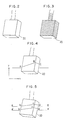
- a spatial coded image shown in Fig. 3 can be obtained by combining the binary coded patterned images in a manner disclosed in Japanese Provisional Patent Publication No. 60-152903. Pattern lines shown by solid lines in Fig. 3 indicate boundaries between adjacent spatial codes.
- the image processing device 15 cooperates with an operator to extract, from the spatial coded image, model data specifying the object 20 which assumes a particular orientation.
- the operator operates the system terminal 17 so as to specify, on the television screen, an image element constituting part of the multi-slit image, e.g., a pattern element curve which extends along symbols A , B and C shown in Fig. 4.
- the pattern element curve changes stepwise in the positive direction of the y axis at the point A , obliquely upwardly extends from the point A to the point B at an angle of ⁇ 1 (not shown) on the xy plane, and changes in a roof (convex) form at the point B . Further, the curve obliquely downwardly extends from the point B to the point C at an angle of ⁇ 2 (not shown), and changes stepwise in the negative direction of the y axis at the point C .
- the image processing device 15 derives the positions of the points A , B and C on the pattern element curve in the space where the vision system is disposed, by means of trigonometric survey, on the basis of geometric parameters (a distance between the projector 11 and the camera 14; an angle formed between a straight line connecting the elements 11, 14 and a straight line connecting the projector 11 and that part of the object 20 which is to be detected; and an angle formed between a straight line connecting the elements 11 and 14 and a straight line connecting the to-be-detected portion of the object) which are known and determined in accordance with the positional relation between the projector 11, camera 14 and object 20.
- geometric parameters a distance between the projector 11 and the camera 14; an angle formed between a straight line connecting the elements 11, 14 and a straight line connecting the projector 11 and that part of the object 20 which is to be detected; and an angle formed between a straight line connecting the elements 11 and 14 and a straight line connecting the to-be-detected portion of the object
- the image processing device derives numeral parameters (preferably, the stepwise changing amounts at the points A and C ; the distance between the points A and B : the distance between the points B and C ; and the angles ⁇ 1 and ⁇ 2) constituting model data which specifies the pattern element curve or the object 20, and causes the derived parameters to be stored into a built-in memory (not shown) of the device 15.
- numeral parameters preferably, the stepwise changing amounts at the points A and C ; the distance between the points A and B : the distance between the points B and C ; and the angles ⁇ 1 and ⁇ 2
- model data creating and storing processes are repeated, while changing the orientation of the object 20, to thereby derive model data obtained when the object assumes several typical orientations.
- the object 20 When the robot or checking system is operated, the object 20 is disposed in the visual field of the camera 14.
- the vision system projects slitted light onto the object 20 to create a slitted light image, and analyzes the image, whereby the object recognition process is performed.
- strip-form light and reversal light reversed in light/darkness as compared with the former light are sequentially projected. This is equivalent to simultaneous projection of two slitted light beams.
- strip-form pattern data is supplied from the image processing device 15 to the liquid crystal controller 13
- corresponding liquid crystal segments of the liquid crystal shutter array 12 are set into the light transmitting state under the control of the controller 12, and strip-form light is projected onto the object 20 from the projector 11 which cooperates with the shutter array.
- the image processing device 15 receives, via the camera 14, an image (first image) of the object 20 obtained when the strip-form light is projected, and causes the image to be stored into one (first frame memory) of the frame memories 15a.
- reversal pattern data is supplied from the image processing device 15 to the controller 13.
- reversal patterned light is projected onto the object 20, and an image (second image) of the object 20 obtained when the reversal patterned light is projected is stored into a second frame memory of the image processing device 15.
- the image processing device 15 subtracts the second image from the first image for respective picture elements to derive a first difference image, and causes the image to be stored into a third frame memory. Also, the device subtracts the first image from the second image to derive a second difference image, and causes the derived image to be stored into a fourth frame memory. Then, the device performs raster-scanning of the first difference image to determine a brightness changing point for each scanning line of the image, and determines variations in the brightness of the second difference image in an area in the vicinity of that point which corresponds to the above brightness changing point. When it is determined that there is that position at which the first difference image changes from darkness to light and at the same time the second difference image changes from light to darkness, such a position is stored into a fifth memory.
- This determining and storing processes are repeated to thereby derive a slitted light image which corresponds to the upper edge of the strip-form light and which is shown by symbols a to e in Fig. 5.
- positions at which the first difference image changes from light to darkness and the second difference image changes from darkness to light are sequentially determined, to thereby derive a slitted light image a' to e' which corresponds to the lower edge of the strip-form light.
- the image processing device 15 derives the positions of the points b , c , d , c' and d' on the slitted light images in the vision system setting space by means of trigonometric survey. Further, the device derives numeral parameters (stepwise variation amounts at the points b , b' , d and d' ; distance between the point b or b' and the point c or c' ; distance between the point c or c' and the point d or d' ; and inclinations of the lines bc, b'c', cd and c'd') which construct collate data for the slitted light images, the collate data corresponding to the model data, and causes the numerical parameters to be stored into the built-in memory.
- numeral parameters stepwise variation amounts at the points b , b' , d and d' ; distance between the point b or b' and the point c or c' ; distance between the point c or
- the image processing device 15 determines whether or not the collate data coincides with any one of the model data. Preferably, a determination is made as to whether or not both of a difference between the distance parameter bc or b'c' of the collate data and the distance parameter AB of the model data, and a difference between the distance parameter cd or c'd' and the distance parameter BC fall within allowable error ranges. Then, if the result of the determination is affirmative, it is determined that the collate data coincides with the model data, and hence the object 20 assumes the orientation specified by the model data. In the meantime, since the distance parameters bc and b'c' and the inclinations of lines bc and b'c' vary in dependence on the orientation of the object 20, the orientation of the object 20 may be determined in accordance with these parameters.
- the image processing device 15 processes an image received via the camera 14, so as to measure the position and orientation of the object 20 in the vision system setting space, in particular, the position of the object along the y axis in the space.
- new strip-form pattern data and new reversal pattern data are sequentially supplied from the image processing device 15 to the liquid crystal controller 13, so that strip-form light and reversal patterned light are sequentially projected on a different portion of the object 20, and the above-mentioned collate process is carried out.
Landscapes
- Engineering & Computer Science (AREA)
- Computer Vision & Pattern Recognition (AREA)
- Physics & Mathematics (AREA)
- General Physics & Mathematics (AREA)
- Length Measuring Devices By Optical Means (AREA)
- Image Analysis (AREA)
Applications Claiming Priority (2)
| Application Number | Priority Date | Filing Date | Title |
|---|---|---|---|
| JP22826089A JPH0392704A (ja) | 1989-09-05 | 1989-09-05 | 光切断法による対象物認識方法 |
| JP228260/89 | 1989-09-05 |
Publications (1)
| Publication Number | Publication Date |
|---|---|
| EP0441972A1 true EP0441972A1 (de) | 1991-08-21 |
Family
ID=16873686
Family Applications (1)
| Application Number | Title | Priority Date | Filing Date |
|---|---|---|---|
| EP19900912936 Withdrawn EP0441972A1 (de) | 1989-09-05 | 1990-09-04 | Methode zur objekterkennung mit hilfe optischer schnittbildverfahren |
Country Status (3)
| Country | Link |
|---|---|
| EP (1) | EP0441972A1 (de) |
| JP (1) | JPH0392704A (de) |
| WO (1) | WO1991003704A1 (de) |
Cited By (3)
| Publication number | Priority date | Publication date | Assignee | Title |
|---|---|---|---|---|
| DE4136428A1 (de) * | 1991-11-05 | 1993-05-06 | Henning Dr. 7440 Nuertingen De Wolf | Moire-verfahren mit elektronischem analysegitter |
| FR2693003A1 (fr) * | 1992-06-30 | 1993-12-31 | Peugeot | Dispositif opto-électronique de numérisation de formes tridimensionnelles d'un objet. |
| EP0563829A3 (en) * | 1992-03-30 | 1994-08-24 | Sharp Kk | Device for inspecting printed cream solder |
Families Citing this family (1)
| Publication number | Priority date | Publication date | Assignee | Title |
|---|---|---|---|---|
| JPH06226669A (ja) * | 1993-01-29 | 1994-08-16 | Daifuku Co Ltd | 物品位置検出装置 |
Family Cites Families (1)
| Publication number | Priority date | Publication date | Assignee | Title |
|---|---|---|---|---|
| JPS59197813A (ja) * | 1983-04-26 | 1984-11-09 | Ishikawajima Harima Heavy Ind Co Ltd | 光切断による姿勢測定方法 |
-
1989
- 1989-09-05 JP JP22826089A patent/JPH0392704A/ja active Pending
-
1990
- 1990-09-04 WO PCT/JP1990/001129 patent/WO1991003704A1/ja not_active Ceased
- 1990-09-04 EP EP19900912936 patent/EP0441972A1/de not_active Withdrawn
Non-Patent Citations (1)
| Title |
|---|
| See references of WO9103704A1 * |
Cited By (3)
| Publication number | Priority date | Publication date | Assignee | Title |
|---|---|---|---|---|
| DE4136428A1 (de) * | 1991-11-05 | 1993-05-06 | Henning Dr. 7440 Nuertingen De Wolf | Moire-verfahren mit elektronischem analysegitter |
| EP0563829A3 (en) * | 1992-03-30 | 1994-08-24 | Sharp Kk | Device for inspecting printed cream solder |
| FR2693003A1 (fr) * | 1992-06-30 | 1993-12-31 | Peugeot | Dispositif opto-électronique de numérisation de formes tridimensionnelles d'un objet. |
Also Published As
| Publication number | Publication date |
|---|---|
| WO1991003704A1 (fr) | 1991-03-21 |
| JPH0392704A (ja) | 1991-04-17 |
Similar Documents
| Publication | Publication Date | Title |
|---|---|---|
| US5461478A (en) | Method and apparatus for measuring three-dimensional position and orientation of an object using light projection | |
| US5987591A (en) | Multiple-sensor robot system for obtaining two-dimensional image and three-dimensional position information | |
| US4933864A (en) | Mobile robot navigation employing ceiling light fixtures | |
| US6763284B2 (en) | Robot teaching apparatus | |
| US7046838B1 (en) | Three-dimensional data input method and apparatus | |
| EP0422946B1 (de) | Digitalisierung einer Oberfläche eines unregelmässig geformten Körpers, zum Beispiel einer Schuhsohle | |
| EP0405623A2 (de) | Anordnung zum Prüfen der Staubdurchlässigkeitseigenschaft | |
| EP1411322B1 (de) | Optischer Sensor zur Messung der Position und Lage eines Objekts in drei Dimensionen | |
| US4776692A (en) | Testing light transmitting articles | |
| EP1459035B1 (de) | Verfahren zur bestimmung entsprechender punkte bei stereoskopischen dreidimensionalen messungen | |
| JPH04188014A (ja) | 車間距離検出装置 | |
| EP0441972A1 (de) | Methode zur objekterkennung mit hilfe optischer schnittbildverfahren | |
| JPH1144533A (ja) | 先行車両検出装置 | |
| El-Hakim | A hierarchical approach to stereo vision | |
| JP2519445B2 (ja) | 工作線追従方法 | |
| JPH05337785A (ja) | 研削ロボットの研削経路修正装置 | |
| JP3589512B2 (ja) | 微細加工製品の検査ポイントマーキング方法、自動寸法検査方法及び自動寸法検査装置 | |
| JP2887656B2 (ja) | レーザ加工装置 | |
| JPS6325871B2 (de) | ||
| JPH01210807A (ja) | 塗膜平滑度自動検査装置 | |
| US20020159073A1 (en) | Range-image-based method and system for automatic sensor planning | |
| US20250138506A1 (en) | Placement identifying apparatus | |
| JP2888368B2 (ja) | 位置測定装置 | |
| JPS6247503A (ja) | 光切断法により円形対象物の位置を3次元的に認識する装置 | |
| KR100216951B1 (ko) | 크로스 해치 패턴 인식장치 및 그 방법 |
Legal Events
| Date | Code | Title | Description |
|---|---|---|---|
| PUAI | Public reference made under article 153(3) epc to a published international application that has entered the european phase |
Free format text: ORIGINAL CODE: 0009012 |
|
| 17P | Request for examination filed |
Effective date: 19910528 |
|
| AK | Designated contracting states |
Kind code of ref document: A1 Designated state(s): DE FR GB |
|
| STAA | Information on the status of an ep patent application or granted ep patent |
Free format text: STATUS: THE APPLICATION HAS BEEN WITHDRAWN |
|
| 18W | Application withdrawn |
Withdrawal date: 19920828 |
|
| R18W | Application withdrawn (corrected) |
Effective date: 19920828 |