EP0441970A1 - Reluctance type motor - Google Patents
Reluctance type motor Download PDFInfo
- Publication number
- EP0441970A1 EP0441970A1 EP19900912486 EP90912486A EP0441970A1 EP 0441970 A1 EP0441970 A1 EP 0441970A1 EP 19900912486 EP19900912486 EP 19900912486 EP 90912486 A EP90912486 A EP 90912486A EP 0441970 A1 EP0441970 A1 EP 0441970A1
- Authority
- EP
- European Patent Office
- Prior art keywords
- position detecting
- torque
- magnetic
- poles
- magnetic poles
- Prior art date
- Legal status (The legal status is an assumption and is not a legal conclusion. Google has not performed a legal analysis and makes no representation as to the accuracy of the status listed.)
- Granted
Links
Images


Classifications
-
- H—ELECTRICITY
- H02—GENERATION; CONVERSION OR DISTRIBUTION OF ELECTRIC POWER
- H02K—DYNAMO-ELECTRIC MACHINES
- H02K16/00—Machines with more than one rotor or stator
-
- H—ELECTRICITY
- H02—GENERATION; CONVERSION OR DISTRIBUTION OF ELECTRIC POWER
- H02K—DYNAMO-ELECTRIC MACHINES
- H02K19/00—Synchronous motors or generators
- H02K19/02—Synchronous motors
- H02K19/10—Synchronous motors for multi-phase current
- H02K19/103—Motors having windings on the stator and a variable reluctance soft-iron rotor without windings
-
- H—ELECTRICITY
- H02—GENERATION; CONVERSION OR DISTRIBUTION OF ELECTRIC POWER
- H02K—DYNAMO-ELECTRIC MACHINES
- H02K29/00—Motors or generators having non-mechanical commutating devices, e.g. discharge tubes or semiconductor devices
- H02K29/06—Motors or generators having non-mechanical commutating devices, e.g. discharge tubes or semiconductor devices with position sensing devices
- H02K29/12—Motors or generators having non-mechanical commutating devices, e.g. discharge tubes or semiconductor devices with position sensing devices using detecting coils using the machine windings as detecting coil
Definitions
- the present invention is related to a reluctance-type motor which is used as a drive source replacing the conventional D.C. motor and induction motor with an inverter, and particularly can be used when a long and narrow having a small diameter is needed rather than the flat-type one.
- the reluctance-type motor has more magnetic poles than the D.C. motor, it is difficult to make and has not ever been put to practical use.
- the reluctance-type motor is a well-known art, and because it provides a very low rotational speed though it provides a large output, it has only partly been used for the arm of a robot as a direct drive unit of a load, but it is not commercially available.
- the first problem is that it is difficult to construct a reluctance-type motor having a small diameter and a large output torque since the number of the magnetic poles is large as compared with a D.C. motor.
- the number of magnetic poles and salient poles is large, the construction is complicated, and there are six systems of exciting coils.
- the magnetic poles and exciting coils are at least 12 for a three-phase full-wave energization.
- the number of the salient poles of the rotor becomes large, at least 14.
- the second problem is that the magnetic energy stored in the exciting coils is remarkably large and a certain time is required for the storage, so that the rise of the energization current delays and a reduced torque occurs.
- the present invention is a three-phase reluctance-type motor comprising: an outer casing provided with side boards on both sides thereof, bearings provided in the center of the side boards, a rotating shaft supported by the bearings for free rotation, a magnetic rotor fixed to the rotating shaft within the outer casing, eight salient poles disposed on the outer periphery of the rotor with an equal width and equal pitch, first and second stationary armatures juxtaposed within said outer casing with the outer periphery thereof being fixed, six first magnetic poles which are pro-jected from the inner peripheral surface of the first stationary armature,opposed to the salient poles through a slight air gap, and excited by three-phase half-wave energization, the magnetic poles existing at axially symmetric positions being in phase, first exciting coils wound around the first magnetic poles, six second magnetic poles which are projected from the innerperipheral surface of the second stationar y armature, opposed to the salientpoles through a slight air gap, and excited by
- a construction in which two or more three-phase, half-wave reluctance-type motors are juxtaposed within an outer casing, the number of magnetic and salient poles per motor decreases.
- the number of magnetic poles is made six and disposed with an equal pitch.
- the salient poles of the rotor is four in number.
- the output torque is multiplied by n. Further, by providing a phase difference of 120/n degrees for the output torque of each motor, the torque ripple can be made small and the characteristics at the start-up time become good.
- the first problem can be solved by the above action.
- the stored magnetic energy of a de-energized exciting coil is prevented by a diode from flowing back to the D.C. power supply, and the large electromotive force at that time is utilized to make rapid the storage of the magnetic energy of the exciting coil to be energized next, thereby making the extinguishment and storage of the magnetic energy rapid to prevent a reduced torque and a counter-torque from occurring.
- the present invention produces the following effects.
- the diameter can be made small so that a long and narrow motor can be formed.
- the leakage magnetic flux is less since the magnetic poles of one phase constitute a pair of magnetic poles, N- and S-poles, and thus the output torque increases.
- the applied voltage is high, the exciting current is held at a preset value by chopper control, and the large stored energy of the exciting current is rapidly extinguished and stored, so that a high-speed revolution is enabled, and a high efficiency and high output torque are obtained.
- the means to solve this conflict is to decrease the number of salient poles, but this means is only one.
- three-phase half-wave energization is provided as shown.
- the present invention solves these problems.
- the magnetic energy stored in an exciting coil is rapidly extinguished by feeding it back to the D.C. power supply of the applied high voltage thereby to prevent the occurrence of a counter-torque, and the magnetic energy storage is made rapid by the applied high voltage thereby to prevent the occurrence of a reduced torque.
- the stored magnetic energy of a de-energized exciting coil is prevented by a diode from being fed back to the D.C. power supply, and the large electromotive force at that time is utilized to make rapid the magnetic energy storage of the exciting coil to be energized next for making the magnetic energy to rapidly disappear and be stored, thereby to prevent the occurrence of a reduced torque and counter-torque. Accordingly, the present invention has an action for solving the second problem.
- Figs. 1 (a) and (b) are explanatory views of the construction of a three-phase, half-wave reluctance-type motor
- Figs. 2 (a) and (b) are development views of the rotor, magnetic poles and exciting coils of the above-mentioned motor
- Figs. 3 (a) and (b) are electric circuit diagrams for obtaining position detecting signals from coils
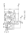
- (b) and (c) are energization control circuits of the exciting coils
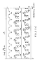
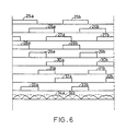
- Figs. 5 (a) and (b) and Fig. 6 are time charts of position detecting signals, exciting currents and output torques
- Figs. 7 (a) and (b) are explanatory views of the whole construction of the apparatus of the present invention.
- angles are all denoted in electrical angles.
- Fig. 1 (a) is a plan view showing the construction of the three-phase, half-wave energization reluctance motor which is an embodiment of the present invention, particularly showing salient poles 1a, 1b, ... of rotor 1 thereof, magnetic poles 16a, ... of stationary armature 16 and exciting coils 17a, ...
- the width of salient poles 1a, 1b, ... of rotor 1 is 120 degrees, an they are disposed with a phase difference of 360 degrees and an equal pitch, respectively.
- Rotor 1 is formed by a well-known means for laminating silicon steel plates, and has rotating shaft 5.
- magnetic poles 16a, 16b, 16c, 16d, 16e and 16f are disposed with an equal spacing angle, the width thereof being 120 degrees.
- the widths of salient poles 1a, 1b, ... and of magnetic poles 16a, ... are 120 degrees and equal.
- the number of the salient poles is four and the number of magnetic poles is six.
- Armature 16 is also constructed by the same means as rotor 1.
- Fig. 2 (a) is a development view of the three-phase, half-wave reluctance-type motor of Fig. 1 (a).
- Coils 10a, 10b and 10c are position detecting elements for detecting the positions of salient poles 1a, 1b, ..., and they are fixed to the armature 16 side at the positions as shown and the coil faces are opposed to the sides of salient poles 1a, 1b, ... through an air gap.
- Coils 10a, 10b and 10c are spaced by 120 degrees.
- the coils have a five millimeter diameter and are of the air core type of about 100 turns.
- a device for obtaining position detecting signals from coils 10a, 10b and 10c.
- Coils 10a, 10b and 10c, and resistors 15a, 15b, 15c ... 15e constitute a bridge circuit, which is adjusted so that it balances when coils 10a, 10b and 10c are not opposed to salient poles 1a, 1b, ...
- Oscillator 7 performs an oscillation of the order of megacycles.
- the voltage drops in resistors 15b and 15c also increase when coils 10b and 10c are opposed to the sides of salient poles 1a and 1b, and thus high-level outputs are obtained from the + terminals of operational amplifiers 13a and 13c through low-pass filter 11b, 12b and another low-pass filter, respectively.
- the outputs signals of operational amplifiers 13a, 13b and 13c are position detecting signals, which are shown in the time chart of Fig. 6 as curves 25a, 25b, ..., curves 26a, 26b, ... and curves 27a, 27b, ...
- the above described three sets of position detecting signals are sequentially delayed in phase by about 120 degrees.
- Logical circuit 8 which is commonly used for three-phase, Y-type D.C. motors, provides continuous position detecting signals having a width of 120 degrees.
- the electric signals of curves 28a, 28b, ... of Fig. 6 can be obtained by ANDing curves 25a, 25b, ... with the inverted outputs of curves 26a, 26b, ...
- the outputs of terminals 6a, 6b, ... 6f of block circuit 8 are shown as curves 28a, 28b, ..., curves 29a, 29b, ..., curves 30a, 30b, ..., curves 31a, 31b, ..., curves 32a, 32b, . .. and curves 33a, 33b, ..., respectively.
- Curves 28a, 29a and 30a are continuous position detecting signals of the first, second and third phases having a width of 120 degrees.
- Curves 31a, 32a and 33a are also continuous position detecting signals of the first, second and third phases having a width of 120 degrees.
- Position detecting signals providing the same action and effect are also obtained if an aluminium plate having the same shape as rotor 1 is syncronously rotated instead of rotor 1 to which coils 10a, 10b and 10c are opposed and coils 10a, 10b and 10c are made to oppose to the projecting portions thereof.
- Similar position detecting signals can also be obtained by utilizing a magnet rotor synchronously rotating with rotor 1 and utilizing the output change of magnetic resistance elements opposed to the magnatic poles thereof.
- coils 10d, 10e and 10f of the same construction are used which are fixed in the same positions as coils 10a, 10b and 10c in Fig. 2 (a), respectively.
- reluctance-type motors have an advantage of very large output torque, they are prevented from being put to practical use because of the following disadvantages.
- the first disadvantage is that the exciting coils can not be bidirectionally energized, so that the electric circuit becomes expensive and the number of magnetic and salient poles becomes large, which complicates the construction.
- the second disadvantage is that the torque is extremely large in the initial stage in which salient poles start to oppose to magnetic poles and it is small in the final stage.
- such means is to make the widths of the opposing faces of the salient and magnetic poles in the direction of the rotating shaft different from each other.
- the flat portions of the output torque curves are increased by the leakage magnetic flux of the opposing faces as shown by dotted curves 41a, 41b, ... in the time chart of Fig. 5 (a), and thus the ripple component of the composite torque can be decreased by the later described means.
- the same object can be achieved be the same means an brushless motors, that is, by performing energization of 120 degrees in width of the central portion.
- the third disadvantage is that only a low-speed operation is available. That is, there is a defect that the rotational speed becomes extremely low and the efficiency also degrades if the exciting current is increased to increase the output torque.
- the rise slope of the exciting current is made relatively gentle by the magnetic energy stored in magnetic poles 16a, 16b, ... and salient poles 1a, 1b, ..., and the time required for the discharge current due to the magnetic energy to disappear at the de-energization time is relatively prolonged, resulting in the occurrence of a large counter-torque.
- circular portion 16 and magnetic poles 16a, 16b, ... are constructed by a well-known means for laminating and solidifying silicon steel plates, and fixed to an outer casing, not shown, to form an armature.
- Circular portion 16 is a magnetic core which is to form a magnetic path, and circular portion 16 and magnetic poles 16a, 16b, ... are referred to as an armature or a stationary armature.
- Exciting coils 17a, 17b, ... are mounted on magnetic poles 16a, 16b, ... Exciting coils 17a and 17d are connected is series or in parallel, and such connecting body is referred to as exciting coil K.
- Exciting coils 17b and 17e and exciting coils 17c and 17f are similarly connected, and these are referred to as exciting coils L and M, respectively.
- exciting coil M When rotor 1 rotates 120 degrees, exciting coil M is de-energized and exciting coil L is energized.
- exciting coil L When rotor 1 further rotates 120 degrees, exciting coil L is de-energized and exciting coil K is energized.
- the energization mode is cyclically changed for each 120 degrees rotation from exciting coil K ⁇ exciting coil M ⁇ exciting coil L ⁇ , and the motor is driven as a three-phase, half-wave motor.
- Magnetic poles existing at axially symmetrical positions at this time are magnetized to the N- and S-poles as shown.
- transistors 20a and 20b, 20c and 20d, and 20e and 20f are inserted at both ends of exciting coils K, M and L, respectively.
- Transistor 20a, 20b, 20c, ... are switching elements, and any other semiconductor elements having the same effect may be used instead of them.
- Power is supplied from positive and negative terminals 2a and 2b of a D. C. power supply.
- transistors 20a and 20b turn on and exciting coil K is energized.
- transistors 20c and 20d, and 20e and 20f turn on and exciting coils M and L are energized.
- Terminal 40 is a reference voltage for specifying the exciting current.
- the output torque can be altered by changing the voltage of terminal 40.
- Resistor 22 is a resistor for detecting the exciting current each exciting coil K, M, L.
- the input signals of terminal 4a are position detecting signals 28a, 28b, ... of Fig. 6, and the input signals of terminals 4b and 4c are position detecting signals 29a, 29b, ... and 30a, 30b, ...
- Curves 28a, 29a and 30a are continuous.
- exciting coil M is energized by typical means for the width of position detecting signal 29a (the width of 120 degrees which is denoted by arrow 36), the rise of the energization current delays because of the large inductance of exciting coil M as shown by the first half portion of dotted line curve 35.
- the fall portion is extended by the discharge of a large magnetic energy as shown by the latter half portion of curve 35.
- the torque decreases in the first half portion of curve 35 and a large counter-torque is generated in the latter half portion. Decreasing of a torque is referred to as generation of a reduced torque. Thus, the efficiency degrades and a low-speed rotation is provided.
- the magnetic energy stored in exciting coil K is discharged through diode 21a, transistor 20b and resistor 22, and when the discharge current decreases to a predetermined value, the output returns to a high-level because of the hysteresis characteristics of operational amplifier 40a and transistor 20a conducts again to increase the exciting current.
- the current value by chopper control, or the output torque is characterized in that it dose not change.
- the apparatus of the present invention is characterized in that the limit of a high-speed rotation and the output are independently controlled by the applied voltage and the reference voltage (the command voltage of the output torque), respectively, and it rotates as a three-phase, half-wave motor.
- Control of the control current by the position detecting signal of exciting coil M changed by the chopper action of operational amplifier 40a and AND circuit 14b in Fig. 4 (a) and depending on turn-on/off of transistor 20a, as shown by dotted line 35b in Fig. 5, and rapidly falls at the end of curve 29a as shown by a dotted line.
- exciting coils K, M and L are sequentially and continuously energized to generate output torques.
- the object of the present invention is also accomplished by a chopper circuit which uses the outputs of AND circuits 14a, 14b and 14c to perform on/off control of transistors 20a and 20b, transistors 20c and 20d, and transistors 20e and 20f, respectively.
- the torque curve of a D. C. motor having a magnet rotor (by N- and S-poles) is symmetrical, but that of a reluctance-type motor is a symmetrical, that is, it is remarkably large in the initial stage in which salient poles enters magnetic poles and it rapidly decreases at the final stage.
- the torque ripple can be reduced even a large output torque.
- the apparatus of the present invention has an action and effect that the torque ripple can be removed by the later described means in connection with Fig. 7 (a).
- Arrow 37 in Fig. 5 (a) is 120 degrees and it is the section in which a positive torque is generated.
- the torque curves by magnetic and salient poles for exciting coil M are curves 41a, 41b, ...
- position detecting elements 10a, 10b and 10c are adjusted and fixed so that energization is initiated when salient poles start to enter magnetic poles and de-energization is performed when the two are completely opposed to each other.
- the section in which a counter-torque occurs is the section of arrow 37a which has the width of the fall portion of curve 35b. If the width of the fall portion is large, there is a defect that a large counter-torque is generated, whereby the output torque and efficiency are reduced.
- the widths of salient poles 1a, 1b, ... are all made greater than 120 degrees and to near 180 degrees. For instance, they are set to 180 degrees.
- salient pole 1b in Fig. 2 (a) is taken as an example, the width thereof is set to the width of arrow F.
- the widths of the other salient poles are also set to 180 degrees.
- Arrow 37c represents a section in which a positive torque is obtained when the widths of both salient and magnetic poles are 180 degrees.
- the salient pole As apparent from the above description, by making the salient pole greater than 120 degrees and near to 180 degrees, the counter-torque due to the fall portion of an exciting can be obviated.
- exciting coils K, M and L are sequentially energized and rotate as a three-phase, half-wave reluctance-type motor.
- the exciting current at this time is as shown by curve 35a in Fig. 5 (a).
- the height of the central flat portion of curve 35a equals to the value which is obtained by dividing the voltage of D.C. power supply terminals 2a, 2b minus the counter-electromotive force (proportional to output curves41a, 42a, ...) by the resistance of an exciting coil.
- the exciting current becomes flat and rises in the latter half portion.
- transistors 20c and 20d have already been turned on by position detecting signal curve 29a, and thus the voltage of capacitor 19 is applied to exciting coil M to make the rise of the exciting current rapid and exciting coil M is energized as shown by curve 35a.
- capacitor 19 may be removed.
- the voltage between terminals 2a and 2b can be a low voltage as in typical D.C. motors, and thus an effective means can be provided which is effective as the drive source of an electric motor car using a battery as its power supply.
- the stored magnetic energy is prevented by diode 18 from being fed back to the power supply, and the electromotive force of the magnetic energy is utilized to store the magnetic energy of the exciting coil to be energized next.
- anti-reverse current diode 18 in Fig. 4 (b) is provided at the positive electrode 2a side of the power supply, the same effect is also produced if it is provided at the negative electrode 2b side of the power supply.
- diode 18 is forwardly inserted (in the direction in which the exciting current flows) between the lower electrode of capacitor 19 and the negative electrode 2b side of the power supply.
- the time width required for the magnetic energy of an exciting coil to disappear and to be stored is about 20 microseconds for a motor having an output of 300 watts, providing for a high-speed rotation of 100,000 revolutions per minute.
- Eddy-current loss included in iron loss can be reduced by such means, thereby increasing the efficiency.
- Fig. 1 (a) magnetic poles in axially symmetrical positions are excited by exciting coils, a construction is provided in which, for example, the forces by which magnetic poles 16a and 16b attract salient poles 1a and 1c in the radial directions cancel each other, and an output torque is obtained by the attraction force in the circumferential direction.
- the gist of the technique of the present invention reside in that two or more three-phase, half-wave energization motors of Fig. 1 (a) are used to form a motor of plural-phase energization.
- Rotors 1-1 and 1-2 are fixed to rotating shaft 5, and four salient poles 1a, 1b, ... are disposed as in rotor 1 as shown in Fig. 2 though they are omitted and not shown.
- stationary armature 16 is fitted in outer casing 42, the magnetic poles are opposed to the salient poles of rotor 1-1 through an air gap. Only magnetic poles 16a and 16d and exciting coils 17a and 17b are shown.
- Aluminium disk 3 is fixed to rotating shaft 5, four projecting portions having the same phase and shape as salient poles 1a, 1b, ... are provided on the outer periphery of disk 3, and to the outer periphery thereof, coils 10a, 10b and 10c fixed to part of side board 42b are opposed which are to become position detecting elements. Only coil 10a, is shown.
- the position detecting signals obtained by coils 10a, 10b and 10c are completely the same as the position detecting signals obtained by the means explained in Fig. 3 (a) or Fig. 3 (b).
- rotor 1 and stationary armature 16 can be driven as the three-phase, half-wave energization motor described in Fig. 1 (a) and Fig. 2 (a).
- Rotor 1 is common to stationary armature 16a as shown in Fig. 7 (a) or divided into rotors 1-1 and 1-2, as shown and the salient poles are at positions in phase.
- Magnetic poles 16a , 16b , ... are opposed to salient poles 1a, 1b, ... through a slight air gap.
- Magnetic poles 16a , 16b , ... are rightward shifted by 60 degrees with respect to magnetic poles 16a, 16b, ...
- the energization of exciting coils 17a , 17b , ... is controlled by a circuit of the same construction as the energization control circuits of Figs. 4 (a) and (b), whereby they are driven as a three-phase, half-wave motor.
- Exciting coils K, M and L in Figs. 4 (a) and (b) become exciting coils 17a , 17d and 17c , 17f and 17b , 17e , respectively.
- the position detecting signals inputted from terminals 4a, 4b and 4c are position detecting signal curves 31a, 32a and 33a in Fig. 6, and become the output signals of terminals 6d, 6e and 6f in Fig. 3 (a).
- Torque curve 34a by the magnetic poles of stationary armature 16 and torque curve 34b by the magnetic poles of stationary armature 16 are shown in Fig. 6.
- Three-phase, half-wave motors of three phases have a dead point at the start-up time, but in accordance with the apparatus of the present invention, the dead point is removed, and there is an effect that the ripple torque of the output torque also becomes small.
- the motor of Fig. 7 (a) is characterized in that it has the same action and effect as three-phase, full-wave reluctance motors, and that the number of magnetic and salient poles is equal to that of three-phase, half-wave motors.
- the phases of the salient poles of rotor 1-1 and 1-2 are equal and the phases of the magnetic poles of stationary armatures 16 and 16 are shifted by 60 degrees from each other. Also, it is possible that the rotor is not divided, but used as one common rotor.
- phase of the magnetic poles of stationary armatures 16 and 16 are made equal, and rotor 1 is divided into two (rotors 1-1, 1-2) and the phases of the respective salient poles are shifted by 60 degrees from each other.
- recessed grooves in the groove portions between the salient poles and also fill the recessed grooved with a plastic material.
- Fig. 7 (a) used two three-phase, half-wave motors, the same object is also attained if two or more motors are juxtaposed.
- the armature of the 2nd motor is fixed to the outer casing at a position the angular phase of which is delayed by 120/n degrees from the armature of the 1st motor with respect to the rotational direction of the rotor.
- the 1st motor, 2nd motor, 3rd motor, ... are disposed in the outer casing so that they are sequentially delayed by 120/n degrees in angular phase.
- the armatures of the n number of motors are disposed in phase in a juxtapositional relationship in the outer casing, and the angular phases of the opposing rotors are sequentially shifted by 120/n degrees.
- the output torque is a sum of output torques the phases of which are sequentially shifted by 120/n degrees, the torque flatness becomes good and the output torque also increases.
- Continuous 120-degrees wide position detecting signals of the first, second and third phases for controlling the energization of the exciting coils of the 1st, 2nd, ... motors, and n number of energization control circuits by which the energization control is performed are required.
- each energization control circuit may be the one having the same construction as described above, the explanation thereof is provided below.
- the outputs of terminals 8a, 8b and 8c are used as the position detecting signals of the first, second and third phases.
- the position detecting signals of the first, second and third phases of each of the fourth, fifth, ... motors can be obtained.
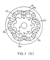
- Fig. 1 (b) is a plan view of the construction of the salient poles of the rotor, the magnetic poles of the stationary armature and the exciting coils of the three-phase, half-wave reluctance motor used for the present invention.
- the width of salient poles 1a, 1b, ... of rotor 1 is 180 degrees, and they are disposed with a phase difference of 360 degrees and an equal pitch, respectively.
- magnetic poles 16a, 16b, 16c, 16d, 16e and 16f each having a width of 180 degrees are disposed at an equal spacing angle.
- the widths of salient poles 1a, 1b, ... and magnetic poles 16a, 16b, ... are of an equal value of 180 degrees.
- the number of the salient poles is eight, and the number of the magnetic poles is six.
- Fig. 2 (b) is a development view of the three-phase reluctance-type motor of Fig. 1 (b) and common to Fig. 2 (a) in the most parts thereof.
- exciting coil L When exciting coil L is energized, salient poles 1b and 1f are attracted and rotor 1 rotates in the direction of arrow A. When rotor 1 rotates 90 degrees, exciting coil L is de-energized and exciting coil M is energized.
- exciting coil M When rotor 1 further rotates 120 degrees, exciting coil M is de-energized and exciting coil K is energized.
- the energization mode is cyclically changed for each 120-degree rotation from exciting coil K ⁇ exciting coil L ⁇ exciting coil M ⁇ , and the motor is driven as a three-phase, half-wave motor.
- Magnetic poles existing at axially symmetrical positions at this time are magnetized to N- and S-poles as shown.
- the output torque is multiplied by n.
- Fig. 4 (c) which is substantially common to Fig. 4 (a) in the construction and action, and the time chart is shown in Fig. 5 (b). This time chart is also substantially common to Fig. 5 (a).
- exciting coil L When exciting coil L is energized for the width of position detecting signal 29a (shown by arrow 36; 120 degrees) by a typical means, the large inductance of exciting coil L causes the rise of the energization current to delay as shown by the first half portion of dotted line curve 35. Also, the fall portion is extended by discharge of the large magnetic energy as shown the latter half portion of curve 35.
- the section of 180 degrees in which a positive torque is generated is denoted by arrow 36b.
- Control of the control current by the position detecting signal of exciting coil L changes depending on on/off of transistor 20c by the chopper action of operational amplifier 40a and AND circuit 14b in Fig. 6, as shown by dotted line 35b in Fig. 5 (b), and rapidly falls at the end of curve 29a as shown by the dotted line.
- exciting coils K, L and M are sequentially and continuously energized to generate an output torque.
- the output torque curve is made symmetrical, for instance, it is only needed to change the shape of the opposing faces of the magnetic and salient poles.
- arrow 36b (180 degrees) in Fig. 5 (b) is the section in which a positive torque is generated, by energizing an exciting coil only for the width of 120 degrees (arrow 36) of the central portion of the section, the output torque can be made large and the torque ripple can be made small.
- the fixing positions of coils 10a, 10b and 10c in Fig. 2 (b) are adjusted so that the energization is begun in the vicinity of the beginning of the torque curves in the third stage of the time chart.
- the exciting current is as shown by dotted line curve 35b.
- Arrow 36 is the width of curve 29a, and arrow 36c is a 180-degrees width in which a positive torque is obtained.
- the exciting currents by the other exciting coils K and M are shown by dotted line curves 35a and 35c, and the actions and effects of them are completely similar.
- Ball bearings 43a and 43b are provided in the central portions of side boards 42a and 42b fixed to both sides of cylindrical outer casing 42, and rotating shaft 5 is supported by bearings 43a and 43b.
- rotor 1 Fixed to rotating shaft 5 is rotor 1, in which eight salient poles 1a, 1b, ... are disposed as shown in Fig. 2 (b).
- stationary armature 16 is fitted in outer casing 42, and magnetic poles 16a, 16b, ... are opposed to salient poles 1a, 1b, ... of rotor 1 through an air gap.
- Aluminium disk 3 is fixed to rotating shaft 5, and in the outer periphery of disk 3, eight projecting portions which are in phase with and have the same shape as salient poles 1a, 1b, ... are provided so that they are projecting, to the outer peripheral faces of which coils 10a, 10b and 10c fixed to part of side board 42b are opposed. Coils 10a, 10b and 10c act as position detecting elements.
- the position detecting signals obtained from coils 10a, 10b and 10c are completely the same as the position detecting signals obtained by the means described in Fig. 3.
- rotor 1 and stationary armature 16 can be driven as the three-phase, half-wave energization motor depicted in Fig. 2 (b).
- stationary armature 16 In stationary armature 16 , six magnetic poles 16a, 16b, ... are projecting, around which exciting coils 17a , 17b , ... are wound.
- Rotor 1 is common to stationary armature 16 as shown in Fig. 7 (b),and magnetic poles 16a , 16b , ... are opposed to salient poles 1a, 1b, ... through a slight air gap.
- Magnetic poles 16a , 16b , ... are shifted to the right by 60 degrees with respect to magnetic poles 16a, 16b, ...
- Exciting coils K, L and M in Figs. 4 (b) and (c) become exciting coils 17a , 17d , exciting coils 17b , 17e and exciting coils 17b , 17e , respectively.
- rotor 1 is made common, and the phases of the magnetic poles of stationary armatures 16 and 16 are shifted by 60 degrees.
- the same action and effect is also provided by putting the magnetic poles of stationary armatures 16 and 16 in phase, and dividing rotor 1 into two and shifting the phases of the respective salient poles by 60 degrees.
- the present invention is a reluctance-type motor which is utilized as a drive source replacing the conventional D.C. motor and induction motor with an inverter, and particularly can be used when a long and narrow motor having a small diameter is required rather than the flat-type one.
Abstract
Description
- The present invention is related to a reluctance-type motor which is used as a drive source replacing the conventional D.C. motor and induction motor with an inverter, and particularly can be used when a long and narrow having a small diameter is needed rather than the flat-type one.
- Since the reluctance-type motor has more magnetic poles than the D.C. motor, it is difficult to make and has not ever been put to practical use.
- The reluctance-type motor is a well-known art, and because it provides a very low rotational speed though it provides a large output, it has only partly been used for the arm of a robot as a direct drive unit of a load, but it is not commercially available.
- It is somewhat used as a small stepping motor, and a wide application therefore has not been developed as yet.
- The first problem is that it is difficult to construct a reluctance-type motor having a small diameter and a large output torque since the number of the magnetic poles is large as compared with a D.C. motor.
- To explain by taking a three-phase, full-wave motor of the reluctance type as an example, the number of magnetic poles and salient poles is large, the construction is complicated, and there are six systems of exciting coils. The magnetic poles and exciting coils are at least 12 for a three-phase full-wave energization.
- Also, the number of the salient poles of the rotor becomes large, at least 14.
- Accordingly, there is a problem that it is difficult to construct a motor of a small diameter.
- Further, since the number of times the magnetic energies of the magnetic energies of the magnetic and poles enter and go out for one rotation increases, there is an inconvenience that increase of the rotational speed is difficult and iron loss increases.
- Next, the second problem is that the magnetic energy stored in the exciting coils is remarkably large and a certain time is required for the storage, so that the rise of the energization current delays and a reduced torque occurs.
- In addition, some time is required for the magnetic energy to disappear, which causes a counter-torque. The occurrences of the reduced torque and counter-torque increase as the rotational speed rises.
- Consequently, there is a problem that the efficiency degrades and the rotational speed becomes extremely small.
- Accordingly, it is the object of the present invention to provide a reluctance-type motor which has a small diameter, large output torque, good efficiency and high rotational speed.
- The present invention is a reluctance-type motor having a plurality of armatures juxtaposed therein comprising: an outer casing provided with side boards on both sides thereof, bearings provided in the center of the side baords, a rotating shaft supported by the bearings for free rotation, a magnetic rotor fixed to the rotating shaft inside the outer casing, four salient poles disposed on the output peripheral surface of the rotor with an equal width and equal spacing angle, n number of stationary armatures (n=2, 3, 4, ...) juxtaposed within the outer casing with the outer periphery thereof being fixed, six magnetic poles of a width of 120 degrees in electrical angle which are projected from the inner peripheral surface of the stationary armatures and disposed with an equal pitch oppositely to the salient poles through a slight air gap, the magnetic poles existing in axially symmetrical positions being in phase, exciting coils of first, second and third phases mounted on the magnetic poles, a position detecting device including a plurality of position detecting elements which detect the positions of the salient poles to provide one set of position detecting signals of continuous rectangular waves of the first, second and third phases having a width of 120 degrees in electrical angle, and n-1 sets of position detecting signals of the same construction the phases of which are sequentially delayed by 120/n degrees in electrical angle from the one set of position detecting signals, switching elements connected to both ends of the exciting coils, diodes reversely connected to the respective series connecting bodies of the exciting coils corresponding to the switching elements, an energization control circuit for allowing the switching elements at both ends of the exciting coils of the first, second and third phases of each the n number of stationary armatures to sequentially conduct by the first, second and third position detecting signals included in the n sets of position detecting signals, thereby for controlling the energization of the exciting coils, means for adjusting the relative positions of the magnetic poles opposing to the salient poles of the rotor so that the driving torques of the rotor by the magnetic poles of the n number of stationary armatures and the salient poles sequentially delayed by 120/n degrees in electrical angle, and for fixing the armatures to the outer casing, means for adjusting the positions of the position detecting elements and fixing them to the stationary armature side so that the output torque due to the energization of the exciting coils of eachphase, becomes a maximum value, means for allowing thedischarge of the stored magnetic energy of the exciting coils by the revers-ely connected diodes and the magnetic energy storage to be performed at a high speed, thereby to hold the occurrences of a reduced torque due to the rise portion of the exciting coils in the initial energization stage end of a counter-torque due to the extension of the fall portion thereof in the final energization stage minimum values.
- Furthermore, the present invention is a three-phase reluctance-type motor comprising: an outer casing provided with side boards on both sides thereof, bearings provided in the center of the side boards, a rotating shaft supported by the bearings for free rotation, a magnetic rotor fixed to the rotating shaft within the outer casing, eight salient poles disposed on the outer periphery of the rotor with an equal width and equal pitch, first and second stationary armatures juxtaposed within said outer casing with the outer periphery thereof being fixed, six first magnetic poles which are pro-jected from the inner peripheral surface of the first stationary armature,opposed to the salient poles through a slight air gap, and excited by three-phase half-wave energization, the magnetic poles existing at axially symmetric positions being in phase, first exciting coils wound around the first magnetic poles, six second magnetic poles which are projected from the innerperipheral surface of the second stationar y armature, opposed to the salientpoles through a slight air gap, and excited by three-phase half-wave energization, the magnetic poles existing at axially symmetrical positions beingin phase, second exciting coils wound around the second magnetic poles, a position detecting device including position detecting elements which detectthe positions of the salient poles to provide first position detecting signals of continuous rectangular waves of the first, second and third phases having a width of 120 degrees in elec-trical angle, and second position detecting signals of continuous rectangular waves of the first, second and third phases having a width of 120 degrees in electrical angle, the second position detecting signals being delayed by 60 degrees in electrical angle from the first position detecting signals, switching elements connected to both ends of the first and second exciting coils, diodes reversely connectedto the respective series connecting bodies of the exciting coils correspond-ing to the switching elements, an energization control circuit for allowing the switching elements connected to the first and second exciting coils to conduct for the widths of the first and second position detecting signals respectively, thereby to energize each exciting coil to generate a three-phase, full-wave output torque, means for adjusting the positions of the po-sition detecting elements and fixing them to the stationary armature side sothat the output torque due to the energization of the exciting coils of eachphase becomes a maximum value, means for adjusting and fixing the relative positions of the first and second magnetic poles opposed to the salient poles of the rotor so that the phase difference between the output torque through the first magnetic poles and the output torque through the second magnetic poles is 60 degrees in electrical angle, and means for allowing thedischarge of the stored magnetic energy of the exciting coils by the reversely connected diodes and the magnetic energy storage to be performed at a high speed, thereby to hold the occurrences of a reduced torque due to therise portion of the exciting coils in the initial energization stage and of a counter-torque due to the extension of the fall portion thereof in the final energization stage at minimum values.
- In accordance with the present invention, a construction is provided in which two or more three-phase, half-wave reluctance-type motors are juxtaposed within an outer casing, the number of magnetic and salient poles per motor decreases.
- In the apparatus of the present invention, by setting the magnetic pole width to 120 degrees in electrical angle, the number of magnetic poles is made six and disposed with an equal pitch. The salient poles of the rotor is four in number.
- Accordingly, a long and narrow motor having a small diameter can be obtained.
- With a construction in which n number of three-phase, half-wave motors are juxtaposed, the output torque is multiplied by n. Further, by providing a phase difference of 120/n degrees for the output torque of each motor, the torque ripple can be made small and the characteristics at the start-up time become good.
- The first problem can be solved by the above action.
- By feeding back the magnetic energy stored in an exciting coil to the D.C. power supply of the applied high voltage, the magnetic energy is extinguished rapidly to prevent a counter-torque from occurring, and a magnetic energy is stored rapidly by the applied high voltage to prevent a reduced torque from occurring.
- Alternatively, the stored magnetic energy of a de-energized exciting coil is prevented by a diode from flowing back to the D.C. power supply, and the large electromotive force at that time is utilized to make rapid the storage of the magnetic energy of the exciting coil to be energized next, thereby making the extinguishment and storage of the magnetic energy rapid to prevent a reduced torque and a counter-torque from occurring.
- Accordingly, there is an action for solving the second problem.
- For this, the present invention produces the following effects.
- First, since the number of salient poles is small, or four, the number of times of entrance and exit of the magnetic energy per rotation is small.
- Consequently, a motor having a high speed and high efficiency can be attained.
- Next, since the number of salient and magnetic poles is small, the diameter can be made small so that a long and narrow motor can be formed.
- Moreover, since the construction is such that n number of three-phase, half-wave motors are juxtaposed, the output torque characteristics become good.
- In addition, the leakage magnetic flux is less since the magnetic poles of one phase constitute a pair of magnetic poles, N- and S-poles, and thus the output torque increases.
- Further, the applied voltage is high, the exciting current is held at a preset value by chopper control, and the large stored energy of the exciting current is rapidly extinguished and stored, so that a high-speed revolution is enabled, and a high efficiency and high output torque are obtained.
- Also, if necessary, only by forwardly adding a diode on the power supply side, the same effect is also obtainted for a lower power supply voltage.
- Furthermore, many of the reluctance-type motors are of the salient pole type, and thus iron loss increases to degrade the efficiency.
- The reason for the remarkably large output torque of reluctance-type motors as compared with ordinary motors is that a large magnetic energy is stored in the salient and magnetic poles thereof. Thus, iron increases.
- The means to solve this conflict is to decrease the number of salient poles, but this means is only one.
- With four salient poles (the width is 120 degrees in electrical angle), three-phase half-wave energization is provided as shown.
- This means causes a dead point in the start-up, which makes self-start impossible, and there is a problem that the output torque decreases by about 30% as compared with a motor with eight salient poles and the ripple torque increases.
- The present invention solves these problems.
- Also, it has a construction in which two reluctance-type motors of three-phase half-wave energization are juxtaposed in an outer casing, and thus the number of magnetic and salient poles per one motor becomes 1/2, whereby the first problem is solved.
- Because of the construction of two motors of three-phase, half-wave energization, there is an action that the same output torque as that of three-phase, full-wave energization is provided.
- The magnetic energy stored in an exciting coil is rapidly extinguished by feeding it back to the D.C. power supply of the applied high voltage thereby to prevent the occurrence of a counter-torque, and the magnetic energy storage is made rapid by the applied high voltage thereby to prevent the occurrence of a reduced torque.
- Alternatively, the stored magnetic energy of a de-energized exciting coil is prevented by a diode from being fed back to the D.C. power supply, and the large electromotive force at that time is utilized to make rapid the magnetic energy storage of the exciting coil to be energized next for making the magnetic energy to rapidly disappear and be stored, thereby to prevent the occurrence of a reduced torque and counter-torque. Accordingly, the present invention has an action for solving the second problem.
- Although the construction is that of a three-phase half-wave motor, substantially the same output torque characteristics as a three-phase, full-wave motor is obtained.
- Figs. 1 (a) and (b) are explanatory views of the construction of a three-phase, half-wave reluctance-type motor, Figs. 2 (a) and (b) are development views of the rotor, magnetic poles and exciting coils of the above-mentioned motor, Figs. 3 (a) and (b) are electric circuit diagrams for obtaining position detecting signals from coils, Figs. 4 (a), (b) and (c) are energization control circuits of the exciting coils, Figs. 5 (a) and (b) and Fig. 6 are time charts of position detecting signals, exciting currents and output torques, and Figs. 7 (a) and (b) are explanatory views of the whole construction of the apparatus of the present invention.
- Now, the present invention is described according to the embodiments thereof with reference to the accompanying drawings.
- Hereinafter angles are all denoted in electrical angles.
- Fig. 1 (a) is a plan view showing the construction of the three-phase, half-wave energization reluctance motor which is an embodiment of the present invention, particularly showing
salient poles rotor 1 thereof,magnetic poles 16a, ... ofstationary armature 16 andexciting coils 17a, ... - The width of
salient poles rotor 1 is 120 degrees, an they are disposed with a phase difference of 360 degrees and an equal pitch, respectively. -
Rotor 1 is formed by a well-known means for laminating silicon steel plates, and has rotatingshaft 5. - In
stationary armature 16,magnetic poles - The widths of
salient poles magnetic poles 16a, ... are 120 degrees and equal. - The number of the salient poles is four and the number of magnetic poles is six.
-
Armature 16 is also constructed by the same means asrotor 1. - Fig. 2 (a) is a development view of the three-phase, half-wave reluctance-type motor of Fig. 1 (a).
-
Coils salient poles armature 16 side at the positions as shown and the coil faces are opposed to the sides ofsalient poles - A description is now made to the case that the width of
salient poles -
Coils - The coils have a five millimeter diameter and are of the air core type of about 100 turns.
- In Fig. 3 (a), a device is shown for obtaining position detecting signals from
coils -
Coils resistors coils salient poles - Accordingly, the output of low-pass filters consisting of
diode 11a andcapacitor 12a, and of diode 11c and capacitor 12c are equal, and thus the output of operational amplifier 13a becomes a low level. - Oscillator 7 performs an oscillation of the order of megacycles.
- Since impedance is decreased by iron loss (eddy-current loss plus hysteresys loss) when
coil 10a is opposed tosalient poles resistor 15a increases and the output of operational amplifier 13a becomes a high level. - The voltage drops in
resistors 15b and 15c also increase whencoils salient poles operational amplifiers 13a and 13c through low-pass filter - The outputs signals of
operational amplifiers curves - The above described three sets of position detecting signals are sequentially delayed in phase by about 120 degrees.
- Logical circuit 8, which is commonly used for three-phase, Y-type D.C. motors, provides continuous position detecting signals having a width of 120 degrees.
- For instance, the electric signals of
curves ANDing curves curves - The outputs of
terminals 6a, 6b, ... 6f of block circuit 8 are shown ascurves -
Curves -
Curves - Position detecting signals providing the same action and effect are also obtained if an aluminium plate having the same shape as
rotor 1 is syncronously rotated instead ofrotor 1 to which coils 10a, 10b and 10c are opposed andcoils - Similar position detecting signals can also be obtained by utilizing a magnet rotor synchronously rotating with
rotor 1 and utilizing the output change of magnetic resistance elements opposed to the magnatic poles thereof. - The next description is on the means for obtaining position detecting signals from
coils salient poles salient poles - The circuit surrounded by dotted line E in Fig. 3 (a) is shown in Fig. 3 (b) by, the same symbol.
- Instead of
coils coils - Since the outputs of
operational amplifiers curves outputs terminals 6a, 6b and 6c in Fig. 3 (a) are obtained. - If three coils of the same construction are fixedly provided oppositely to
salient poles
curves terminals 6d, 6e and 6f in Fig. 3 (a). - Consequently, since position detecting signals of the same nature as Fig. 3 (a) can be obtained, they can be used for the same object.
- Although reluctance-type motors have an advantage of very large output torque, they are prevented from being put to practical use because of the following disadvantages.
- The first disadvantage is that the exciting coils can not be bidirectionally energized, so that the electric circuit becomes expensive and the number of magnetic and salient poles becomes large, which complicates the construction.
- Accordingly, it is difficult to make a motor having a small diameter.
- In the apparatus of the present invention, by forming a three-phase, half-wave motor, the above stated disadvantage is removed and the inconvenience due to half-wave energization is also removed.
- The second disadvantage is that the torque is extremely large in the initial stage in which salient poles start to oppose to magnetic poles and it is small in the final stage.
- In consequence, there is drawback that the composite torque also contains a large ripple torque.
- The following means is effective in removing such drawback.
- That is, such means is to make the widths of the opposing faces of the salient and magnetic poles in the direction of the rotating shaft different from each other. With such means, the flat portions of the output torque curves are increased by the leakage magnetic flux of the opposing faces as shown by
dotted curves - Accordingly, the drawback can be eliminated.
- Alternatively, by making the torque curve of one magnetic pole symmetrical by another well-known means, the same object can be achieved be the same means an brushless motors, that is, by performing energization of 120 degrees in width of the central portion.
- The third disadvantage is that only a low-speed operation is available. That is, there is a defect that the rotational speed becomes extremely low and the efficiency also degrades if the exciting current is increased to increase the output torque.
- Usually, to increase the output torque in reluctance-type motors, it is reguired to increase the number of
magnetic poles salient poles - If, at this time, the number of revolutions is held at a required value, the rise slope of the exciting current is made relatively gentle by the magnetic energy stored in
magnetic poles salient poles - Owing to such circumstances, the peak value of the exciting current becomes small and a counter-torque also occurs, so that the rotational speed becomes low. The efficiency also degrades.
- In accordance with the apparatus of the present invention, above described disadvantages are removed as detailed later in connection with the embodiment.
- In the plan view of Fig. 1 (a) and the development view of Fig. 2 (a),
circular portion 16 andmagnetic poles -
Circular portion 16 is a magnetic core which is to form a magnetic path, andcircular portion 16 andmagnetic poles -
Exciting coils magnetic poles Exciting coils -
Exciting coils exciting coils - When exciting coil M is energized,
salient poles rotor 1 rotates in the direction of arrow A. - When
rotor 1 rotates 120 degrees, exciting coil M is de-energized and exciting coil L is energized. - When
rotor 1 further rotates 120 degrees, exciting coil L is de-energized and exciting coil K is energized. - The energization mode is cyclically changed for each 120 degrees rotation from exciting coil K →exciting coil M →exciting coil L →, and the motor is driven as a three-phase, half-wave motor.
- Magnetic poles existing at axially symmetrical positions at this time are magnetized to the N- and S-poles as shown.
- Since two magnetic poles to be excited are always heteropolar, the leakage magnetic fluxes passing through the unexcited magnetic poles are in the directions opposite to each other, whereby the occurrence of a counter-torque is prevented.
- Means for energizing exciting coils K, M and L is described below.
- In Fig. 4 (a),
transistors -
Transistor - Power is supplied from positive and
negative terminals - If a high-level electric signal is inputted from terminal 4a when the lower input of AND
circuit 14a is at a high level,transistors - Similarly, if high-level electric signals are inputted from
terminals 4b and 4c,transistors -
Terminal 40 is a reference voltage for specifying the exciting current. The output torque can be altered by changing the voltage ofterminal 40. - When the power supply switch (not shown) is turned on, the output of
oprational amplifier 40a becomes a high level since the input to the - terminal ofoperational amplifier 40a is lower than that to the + terminal, and thustransistors -
Resistor 22 is a resistor for detecting the exciting current each exciting coil K, M, L. - The input signals of terminal 4a are
position detecting signals terminals 4b and 4c areposition detecting signals - The above-mentioned curves are shown by the same symbols in the first stage of the time chart of Fig. 5 (a).
-
Curves - The energization of each exciting coil is described now with reference to the time chart of Fig. 5 (a).
- If exciting coil M is energized by typical means for the width of
position detecting signal 29a (the width of 120 degrees which is denoted by arrow 36), the rise of the energization current delays because of the large inductance of exciting coil M as shown by the first half portion of dottedline curve 35. - Also, the fall portion is extended by the discharge of a large magnetic energy as shown by the latter half portion of
curve 35. - The section of 120 degrees in which a positive torque is generated is shown by
arrow 36b. - Accordingly, the torque decreases in the first half portion of
curve 35 and a large counter-torque is generated in the latter half portion. Decreasing of a torque is referred to as generation of a reduced torque. Thus, the efficiency degrades and a low-speed rotation is provided. - One characteristic feature of the apparatus of the present invention resides in removing such inconvenience. This is explained below.
- If the applied voltage to terminal 2a is made high, the exciting current rapidly rises as shown by dogged
line curve 35b and the generation of a reduced torque is suppressed. - The stated circumstances are also applied to exciting coil K by position detecting
signal curve 28a, and excitingcurrent curve 35a rapidly rises. - Since the widths of
curves terminal 2a. - If the exciting current exceeds a preset value (specified by the reference voltage of
terminal 40 in Fig. 4 (a)), the output ofoperational amplifier 40a becomes a low level, and thus the output of ANDcircuit 14a becomes a low level to turn offtransistor 20a. - Accordingly, the magnetic energy stored in exciting coil K is discharged through
diode 21a,transistor 20b andresistor 22, and when the discharge current decreases to a predetermined value, the output returns to a high-level because of the hysteresis characteristics ofoperational amplifier 40a andtransistor 20a conducts again to increase the exciting current. - When the exciting current increases to the preset value restricted by
reference voltage 40, the output ofoperational amplifier 40a becomes a low level andtransistor 20a turns off to decrease the exciting current. - This is a chopper circuit repeating such cycle.
- At the end of
curve 28a, the input to terminal 4a in Fig. 4 (a) disappears. - Consequently, since both
transistors diode 21b →power supply terminals diode 21a, whereby the energy is fed back to the power supply. Since usually a capacitor having a large capacity for rectification exists in the power supply, the magnetic energy is stored in the capacitor. The width of the fall portion ofcurve 35a decreases as the power supply voltage increases. If the width of the fall portion is made smaller, a counter-torque occurs less often. - The above described circumstances are completely applied to the other energization curves 35b and 35c, and the action and effect is also the same.
- Since the widths of
curves curves - However, the current value by chopper control, or the output torque is characterized in that it dose not change.
- Further, to increase the output torque, it is only needed to rise the voltage of
reference voltage 40 in Fig. 4 (a). - As described above, the apparatus of the present invention is characterized in that the limit of a high-speed rotation and the output are independently controlled by the applied voltage and the reference voltage (the command voltage of the output torque), respectively, and it rotates as a three-phase, half-wave motor.
- Control of the control current by the position detecting signal of exciting coil M (the input signal at terminal 4b) changed by the chopper action of
operational amplifier 40a and ANDcircuit 14b in Fig. 4 (a) and depending on turn-on/off oftransistor 20a, as shown by dottedline 35b in Fig. 5, and rapidly falls at the end ofcurve 29a as shown by a dotted line. - Next, when
position detecting signal 30a is inputted to terminal 4c in Fig. 4 (a), the energization of exciting coil L is similarly performed. - As described above, exciting coils K, M and L are sequentially and continuously energized to generate output torques.
- Although the chopper control by turn-on/off of
transistors circuits transistors transistors transistors - The torque curve of a D. C. motor having a magnet rotor (by N- and S-poles) is symmetrical, but that of a reluctance-type motor is a symmetrical, that is, it is remarkably large in the initial stage in which salient poles enters magnetic poles and it rapidly decreases at the final stage.
- There is also a motor by which the output torque curve is made symmetrical.
- For instance, it is only needed to change the shape of the opposing faces of magnetic and salient poles.
- In this case, since
arrow 36b (120 degrees) in Fig. 5 (a) is the section in which a positive torque is generated, the torque ripple can be made small by energizing the exciting coil for the width of 120 degrees (arrow 36). - However, a counter-torque is generated in a point in the width of
arrow 36a which is the width of the fall portion of exciting current 35b, there is an inconvenience that the torque is reduced. - The circumstances are the same for the other exciting
current curves - In addition, there is an inconvenience that a dead point exists in the boundaries of the position detecting signals and the start-up is difficult. The means for removing the latter inconvenience is described later with respect to Fig. 7 (a).
- The former inconvenience is described in more detail.
- In the torque curves, the flat portions increase as in
curves 41d, 41c,... - However, there is an inconvenience that the flat portion of a torque decreases as the exciting current increases, as seen from
curves - Accordingly, the torque ripple increases as the exciting current increases.
- As stated above, by changing the shape of the opposing faces of the magnetic and salient poles, the torque ripple can be reduced even a large output torque.
- The apparatus of the present invention has an action and effect that the torque ripple can be removed by the later described means in connection with Fig. 7 (a).
-
Arrow 37 in Fig. 5 (a) is 120 degrees and it is the section in which a positive torque is generated. - The torque curves by magnetic and salient poles for exciting coil M are
curves - The positions of
position detecting elements - After the salient poles completely opposes to the magnetic poles, a counter-torque occurs as shown by curve 41.
- The section in which a counter-torque occurs is the section of arrow 37a which has the width of the fall portion of
curve 35b. If the width of the fall portion is large, there is a defect that a large counter-torque is generated, whereby the output torque and efficiency are reduced. - The means for removing such defect is described below.
- The widths of
salient poles - If
salient pole 1b in Fig. 2 (a) is taken as an example, the width thereof is set to the width of arrow F. The widths of the other salient poles are also set to 180 degrees. - In accordance with the above-mentioned means, a positive torque appears in the section of arrow 37a and a small counter-torque occurs in the section of
arrow 37b. -
Arrow 37c represents a section in which a positive torque is obtained when the widths of both salient and magnetic poles are 180 degrees. - As apparent from the above description, by making the salient pole greater than 120 degrees and near to 180 degrees, the counter-torque due to the fall portion of an exciting can be obviated.
- The above described circumstances are completely applied to the embodiment of Fig. 4 (b) which is described later.
- The electric circuit of Fig. 4 (b) is now described in detail.
- From
terminals signal curves - Accordingly, exciting coils K, M and L are sequentially energized and rotate as a three-phase, half-wave reluctance-type motor.
- The exciting current at this time is as shown by
curve 35a in Fig. 5 (a). The height of the central flat portion ofcurve 35a equals to the value which is obtained by dividing the voltage of D.C.power supply terminals - Thus, the exciting current becomes flat and rises in the latter half portion.
- Since such rise of the current value increases the torque, there is an action that the torque reduction in the latter half portion in
torque curves - When energization is stopped at the end of
curve 28a, the magnetic energy stored in exciting coil K is prevented by anti-reverse current diode 18 from being fed back to the D.C. power supply side, but it chargescapacitor 19 viadiodes - Consequently, the magnetic energy rapidly disappears and the current falls as the fall portion of
curve 35a. - At this time,
transistors signal curve 29a, and thus the voltage ofcapacitor 19 is applied to exciting coil M to make the rise of the exciting current rapid and exciting coil M is energized as shown bycurve 35a. - The energization after the rise becomes flat completely similarly to the case described as to
curve 35a. - The rise and fall portions of exciting
current curves - Since the widths of the above-mentioned rise and fall portions correspondingly decreases as the capacity of
capacitor 19 is reduced, the occurrence of a reduced torque and counter-torque is prevented even for a high speed, providing a characteristic feature of an efficient high-speed rotation. - If there is no time difference in on/off of
transistors capacitor 19 may be removed. - Also, by increasing the capacity of
capacitor 19 in correspondence to the rotational speed, the output torque can be increased and mechanical noises can be made little. - Since the magnetic energy in an exciting coil is not fed back to the D.C. power supply as in the previous embodiment, the voltage between
terminals - In reluctance-type motors, the extinguishment and storage of the large stored magnetic energy in the exciting coils, which causes a large output torque, lead to reduction of the rotational speed, and this is a drawback.
- In the embodiment of Fig. 4 (a), however, the rise and fall of the exciting current of each exciting coil are made rapid by a chopper circuit and a high power supply voltage, whereby the drawback is removed.
- In the embodiment of Fig. 4 (b), the stored magnetic energy is prevented by diode 18 from being fed back to the power supply, and the electromotive force of the magnetic energy is utilized to store the magnetic energy of the exciting coil to be energized next.
- Accordingly, the extinguishment and storage of the magnetic energy becomes rapid thereby to obviate the above drawback, and there is an additional of a low-voltage power supply.
- If an anti-reverse current diode is inserted at the
positive voltage terminal 2a in Fig. 4 (a) , the current is controlled by a chopper circuit, and the same action and effect as described above is also provided for a low power supply voltage. - As previously described on the time chart of Fig. 5 (a), the same effect is also provided in the circuit of Fig. 4 (b) by performing energization of 120 degrees from point C at which salient poles started to enter magnetic poles (Fig. 5 (a)).
- Although anti-reverse current diode 18 in Fig. 4 (b) is provided at the
positive electrode 2a side of the power supply, the same effect is also produced if it is provided at thenegative electrode 2b side of the power supply. - In this case, diode 18 is forwardly inserted (in the direction in which the exciting current flows) between the lower electrode of
capacitor 19 and thenegative electrode 2b side of the power supply. - If the capacity of
capacitor 19 is 0.1 microfarad or less, the time width required for the magnetic energy of an exciting coil to disappear and to be stored is about 20 microseconds for a motor having an output of 300 watts, providing for a high-speed rotation of 100,000 revolutions per minute. - For the normal rotational speed, it is desirable increase the capacity of
capacitor 19 within a range in which the occurrence of a counter-torque can be prevented. - Eddy-current loss included in iron loss can be reduced by such means, thereby increasing the efficiency.
- Since the rise of the exciting current delays in this case, it is desirable to adjust the fixing positions of
position detecting elements - In Fig. 1 (a), magnetic poles in axially symmetrical positions are excited by exciting coils, a construction is provided in which, for example, the forces by which
magnetic poles salient poles - The gist of the technique of the present invention reside in that two or more three-phase, half-wave energization motors of Fig. 1 (a) are used to form a motor of plural-phase energization.
- Referring to the sectional view of Fig. 7 (a), the case of two motors is described in detail.
- In the central portions of
side boards outer casing 42,ball bearings 43a and 43b are provided, by which rotatingshaft 5 is supported. - Rotors 1-1 and 1-2 are fixed to
rotating shaft 5, and foursalient poles rotor 1 as shown in Fig. 2 though they are omitted and not shown. - The outer periphery of
stationary armature 16 is fitted inouter casing 42, the magnetic poles are opposed to the salient poles of rotor 1-1 through an air gap. Onlymagnetic poles exciting coils -
Aluminium disk 3 is fixed torotating shaft 5, four projecting portions having the same phase and shape assalient poles disk 3, and to the outer periphery thereof,coils side board 42b are opposed which are to become position detecting elements.Only coil 10a, is shown. - The position detecting signals obtained by
coils - Accordingly,
rotor 1 andstationary armature 16 can be driven as the three-phase, half-wave energization motor described in Fig. 1 (a) and Fig. 2 (a). -
Stationary armature 16 the outer periphery of which is fixed toouter casing 42 is now described in detail with reference to Fig. 2 (a). - From
stationary armature 16, sixmagnetic poles exciting coils -
Rotor 1 is common tostationary armature 16a as shown in Fig. 7 (a) or divided into rotors 1-1 and 1-2, as shown and the salient poles are at positions in phase. -
Magnetic poles salient poles -
Magnetic poles magnetic poles - The energization of
exciting coils - Exciting coils K, M and L in Figs. 4 (a) and (b) become
exciting coils - The position detecting signals inputted from
terminals signal curves terminals 6d, 6e and 6f in Fig. 3 (a). - In Fig. 5 (a), only curves 33a, 31a and 32a are shown, and the exciting currents are shown by dotted
lines - The action and effect by energization is similar to that of the three-phase, half-wave energization motor including
stationary armature 16. - Torque curve 34a by the magnetic poles of
stationary armature 16 and torque curve 34b by the magnetic poles ofstationary armature 16 are shown in Fig. 6. - Since the above-mentioned torque curves change depending on the torque curve of one magnetic pole, one example is shown.
- Three-phase, half-wave motors of three phases have a dead point at the start-up time, but in accordance with the apparatus of the present invention, the dead point is removed, and there is an effect that the ripple torque of the output torque also becomes small.
- As understood from the above description, the motor of Fig. 7 (a) is characterized in that it has the same action and effect as three-phase, full-wave reluctance motors, and that the number of magnetic and salient poles is equal to that of three-phase, half-wave motors.
- Accordingly, there is an effect that the diameter can be made small to obtain a long and narrow motor. There is also an effect that a high-speed rotation is obtained.
- In this embodiment, the phases of the salient poles of rotor 1-1 and 1-2 are equal and the phases of the magnetic poles of
stationary armatures - The same action and effect is provided if the phase of the magnetic poles of
stationary armatures rotor 1 is divided into two (rotors 1-1, 1-2) and the phases of the respective salient poles are shifted by 60 degrees from each other. - When
rotor 1 of Fig. 1 (a) rotates at a high speed greater than 10,000 revolutions per minute, an air vortex is caused bysalient poles - In order to prevent this, if the grooves between the respective salient poles are filled with a plastic material to remove the irregularities of the rotating circular surface, the above-mentioned siren-like sound disappears.
- To prevent the filled plastic material from being peeled off by a centrifugal force, it is preferred to provide recessed grooves in the groove portions between the salient poles and also fill the recessed grooved with a plastic material.
- Although the embodiment of Fig. 7 (a) used two three-phase, half-wave motors, the same object is also attained if two or more motors are juxtaposed.
- In the case of a plurality of phases in which n number (n=2, 3, ...) of three-phase, half-wave motors are juxtaposed, if they are called the 1st, 2nd, 3rd, ... motors in the order of juxtaposition, the armature of the 2nd motor is fixed to the outer casing at a position the angular phase of which is delayed by 120/n degrees from the armature of the 1st motor with respect to the rotational direction of the rotor.
- Generally speaking, the 1st motor, 2nd motor, 3rd motor, ... are disposed in the outer casing so that they are sequentially delayed by 120/n degrees in angular phase.
- To achieve the same object, it is also possible that the armatures of the n number of motors are disposed in phase in a juxtapositional relationship in the outer casing, and the angular phases of the opposing rotors are sequentially shifted by 120/n degrees.
- Since the output torque is a sum of output torques the phases of which are sequentially shifted by 120/n degrees, the torque flatness becomes good and the output torque also increases.
- Continuous 120-degrees wide position detecting signals of the first, second and third phases for controlling the energization of the exciting coils of the 1st, 2nd, ... motors, and n number of energization control circuits by which the energization control is performed are required.
- Since the position detecting signals are different though each energization control circuit may be the one having the same construction as described above, the explanation thereof is provided below.
- Regarding the position detecting signals of the first motor, from the circuit of Fig. 3 (b), the outputs of
terminals - By a circuit having the same construction as Fig. 3 (b) in which coils 10g, 10h and 10i of the same construction as
coils coils - By the same means as that described above in which three coils having the same construction as coils 10g, 10h and 10i are provided at positions which are delayed by 120/n degrees from coils 10g, 10h and 10i, respectively, the position detecting signals of the first, second and third signals of the third motor are obtained.
- By a similar means, the position detecting signals of the first, second and third phases of each of the fourth, fifth, ... motors can be obtained.
- Fig. 1 (b) is a plan view of the construction of the salient poles of the rotor, the magnetic poles of the stationary armature and the exciting coils of the three-phase, half-wave reluctance motor used for the present invention.
- The construction of it is mostly common to that of the embodiment of Fig. 1 (a).
- The width of
salient poles rotor 1 is 180 degrees, and they are disposed with a phase difference of 360 degrees and an equal pitch, respectively. - In
stationary armature 16,magnetic poles - The widths of
salient poles magnetic poles - The number of the salient poles is eight, and the number of the magnetic poles is six.
- Fig. 2 (b) is a development view of the three-phase reluctance-type motor of Fig. 1 (b) and common to Fig. 2 (a) in the most parts thereof.
- When exciting coil L is energized,
salient poles rotor 1 rotates in the direction of arrow A. Whenrotor 1 rotates 90 degrees, exciting coil L is de-energized and exciting coil M is energized. - When
rotor 1 further rotates 120 degrees, exciting coil M is de-energized and exciting coil K is energized. - The energization mode is cyclically changed for each 120-degree rotation from exciting coil K →exciting coil L →exciting coil M →, and the motor is driven as a three-phase, half-wave motor.
- Magnetic poles existing at axially symmetrical positions at this time are magnetized to N- and S-poles as shown.
- Since two magnetic poles to be excited are always heteropolar, the leakage magnetic fluxes passing through unexcited magnetic poles are in the directions opposite to each other, the occurrence of a counter-torque is prevented.
- According to a well-known means of providing n number (n=2, 3, ...) of projecting teeth having a width and pitch which are equal to those of
magnetic poles - Now, the energization means of exciting coils K, L and M are described with reference to Fig. 4 (c) which is substantially common to Fig. 4 (a) in the construction and action, and the time chart is shown in Fig. 5 (b). This time chart is also substantially common to Fig. 5 (a).
- When exciting coil L is energized for the width of
position detecting signal 29a (shown byarrow 36; 120 degrees) by a typical means, the large inductance of exciting coil L causes the rise of the energization current to delay as shown by the first half portion of dottedline curve 35. Also, the fall portion is extended by discharge of the large magnetic energy as shown the latter half portion ofcurve 35. The section of 180 degrees in which a positive torque is generated is denoted byarrow 36b. - Control of the control current by the position detecting signal of exciting coil L (input signal to terminal 4b) changes depending on on/off of
transistor 20c by the chopper action ofoperational amplifier 40a and ANDcircuit 14b in Fig. 6, as shown by dottedline 35b in Fig. 5 (b), and rapidly falls at the end ofcurve 29a as shown by the dotted line. - Then, when
position detecting signal 30a is inputted to terminal 4c in Fig. 6, exciting coil M is similarly energized. - As explained above, exciting coils K, L and M are sequentially and continuously energized to generate an output torque.
- If the output torque curve is made symmetrical, for instance, it is only needed to change the shape of the opposing faces of the magnetic and salient poles.
- Since, in this case,
arrow 36b (180 degrees) in Fig. 5 (b) is the section in which a positive torque is generated, by energizing an exciting coil only for the width of 120 degrees (arrow 36) of the central portion of the section, the output torque can be made large and the torque ripple can be made small. - The case of a symmetrical torque curves is described below.
- If the magnetic pole widths in the axial direction of the rotating shaft are made different from each other, the flat portions of the torque curves increase as shown by
curves - However, as seen from
curves - Accordingly, if the starting point of energization is made earlier than the energization of 120 degrees in the central portion of the torque curves (the above stated case), the output torques become larger and the flatness of the output torque curves becomes better.
- Now, the explanation thereof is provided with reference to the time chart in the third stage of Fig. 5 (b). The torques are flat on the right side of dotted line B, and the widths of the flat portions are narrow as the exciting currents increase. The exciting currents increase in the order of
curves - To explain exciting coil L by way of example, the fixing positions of
coils - The exciting current is as shown by dotted
line curve 35b. -
Arrow 36 is the width ofcurve 29a, andarrow 36c is a 180-degrees width in which a positive torque is obtained. - If the width of the fall portion of
curve 35b is smaller thanarrow 36b, no counter-torque occurs. - Since this width is two
times arrow 36a, a motor of a higher speed can be obtained. - In addition, since the flat portion of the output torque becomes longer, there is a characteristic feature that the output torque ripple becomes smaller.
- The exciting currents by the other exciting coils K and M are shown by dotted line curves 35a and 35c, and the actions and effects of them are completely similar.
- Since the length of the flat portions of
torque curves - Its detail is explained in connection with the sectional view of Fig. 7 (b).
-
Ball bearings 43a and 43b are provided in the central portions ofside boards outer casing 42, androtating shaft 5 is supported bybearings 43a and 43b. - Fixed to
rotating shaft 5 isrotor 1, in which eightsalient poles - The outer periphery of
stationary armature 16 is fitted inouter casing 42, andmagnetic poles salient poles rotor 1 through an air gap. - Only
magnetic poles exciting coils -
Aluminium disk 3 is fixed torotating shaft 5, and in the outer periphery ofdisk 3, eight projecting portions which are in phase with and have the same shape assalient poles side board 42b are opposed.Coils -
Only coil 10a is shown. - The position detecting signals obtained from
coils - Accordingly,
rotor 1 andstationary armature 16 can be driven as the three-phase, half-wave energization motor depicted in Fig. 2 (b). -
Stationary armature 16 the outer periphery of which is fixedouter casing 42 is now described in detail with reference to Fig. 2 (b). - In
stationary armature 16, sixmagnetic poles exciting coils -
Rotor 1 is common tostationary armature 16 as shown in Fig. 7 (b),andmagnetic poles salient poles -
Magnetic poles magnetic poles - By performing the energization control of
exciting coils - Exciting coils K, L and M in Figs. 4 (b) and (c) become
exciting coils exciting coils exciting coils - In this embodiment,
rotor 1 is made common, and the phases of the magnetic poles ofstationary armatures - Alternatively, the same action and effect is also provided by putting the magnetic poles of
stationary armatures rotor 1 into two and shifting the phases of the respective salient poles by 60 degrees. - The present invention is a reluctance-type motor which is utilized as a drive source replacing the conventional D.C. motor and induction motor with an inverter, and particularly can be used when a long and narrow motor having a small diameter is required rather than the flat-type one.
Claims (2)
- A reluctance-type motor having a plurality of armatures juxtaposed therein comprising:
an outer casing provided with side boards on both sides thereof,
bearings provided in the centers of said side boards,
a rotating shaft supported by said bearings for free rotation,
a magnetic rotor fixed to said rotating shaft within said outer casing,
four salient poles disposed on the outer periphery of said rotor with an equal width and equal spacing angle,
n number (n=2, 3, 4, ...) of stationary armature juxtaposed within said outer casing with the outer periphery thereof being fixed,
six magnetic poles having a width of 120 degrees in electrical angle which are projected from the inner peripheral surface of said stationary armatures and disposed with an equal pitch oppositely to said salient poles through a slight air gap, said magnetic poles existing at axially symmetrical positions being in phase,
exciting coils of first, second and third phases mounted on said magnetic poles,
a position detecting device including a plurality of position detecting elements which detect the positions of said salient poles to provides one set of position detecting signals of continuous rectangular waves of the first, second and third phases having a width of 120 degrees in electrical angle, and n-1 sets of position detecting signals of the same construction the phases of which are sequentially delayed by 120/n degrees in electrical angle from those of said one set of position detecting signals,
switching elements connected to both ends of said exciting coils,
diodes reversely connected to the respective series connecting bodies of the exciting coils corresponding to said switching elements,
an energization control circuit for allowing said switching elements at both ends of said exciting coils of the first, second and third phases of each of said n number of stationary armatures to sequentially conduct by the first, second and third position detecting signals included in said n sets of position detecting signals, thereby performing the energization control of said exciting coils.
means for adjusting the relative positions of the magnetic poles opposing to the salient poles of said rotor so that the driving torques of said rotor by the magnetic poles of said n number of armatures and the salient poles sequentially delay by 120/n degrees in electrical angle, and for fixing armatures to said outer casing,
means for adjusting the positions of said position detecting elements and fixing them to the stationary armature side so that the output torque due to the energization of the exciting coils of each phase becomes a maximum value, and
means for allowing the discharge of the stored magnetic energy of said exciting coils by said reversely connected diodes and the magnetic energy storage to be performed at a high speed, thereby to hold the occurrences of a reduced torque due to the rise portion of said exciting coils in the initial energization stage and of a counter-torque due to the extension of the fall portion thereof in the final energization stage at minimum values. - A three-phase reluctance-type motor comprising:
an outer casing provided with side boards on both sides thereof,
bearings provided in the center of said side boards,
a rotating shaft supported by said bearings for free rotation,
a magnetic rotor fixed to said rotating shaft within said outer casing,
eight salient poles disposed on the outer peripheral surface of said rotor with an equal width and equal pitch, first and second stationary armature juxtaposcd within said outer cas, ing with the outer periphery thereof being fixed,
six first magnetic poles which are projected from the inner peripheral surface of said first stationary armature, opposed to said salient poles through a slight air gap, and excited by three-phase, half-wave energization, said magnetic poles existing at axially symmetrical positions being in phase,
first exciting coils wound around said first magnetic poles,
six second magnetic poles which are projected from the inner peripheral surface of said second stationary armature, opposed to said salient poles through a slight air gap, and excited by three-phase, half-wave energization, said magnetic poles existing at axially symmetrical positions being in phase,
second exciting coils wound around said second magnetic poles,
a position detecting device including position detecting elements which detect the positions of said salient poles to provide first position detecting signals of continuous rectangular waves of first, second and third phases having a width of 120 degrees in electrical angle, and second position detecting signals of continuous rectangular waves of the first, sec ond and third phases having a width of 120 degrees in electrical angle, said second position detecting signals being delayed by 60 degrees in electrical angle from said first position detecting signals,
switching elements connected to both ends of said first and second exciting coils,
diodes reversely connected to the respective series connecting bodies of the exciting coils corresponding to said switching elements,
an energization control circuit for allowing said switching elements connected to said first and second exciting coils to conduct for the widths of said first and second position detecting signals, respectively, thereby to energize each exciting coil to generate a three-phase, full-wave output torque,
means for adjusting the positions of said position detecting elements and fixing them to the stationary armature side so that the output torque due to the energization of said exciting coils of each phase becomes a maximum value,
means for adjusting and fixing the relative positions of said first and second magnetic poles opposed to the salient poles of said rotor so that the phase difference between the output torque through said first magnetic poles and the output torque through said second magnetic poles is 60 degrees in electrical angle, and
means for allowing the discharge of the stored magnetic energy of said exciting coils by the reversely connected diodes and the magnetic energy storage to be performed at a high speed, thereby to hold the occurrences of a reduced torque due to the rise portion of said exciting coils in the initial energization stage and of a counter-torque due to the extension of the fall portion thereof in the final energization stage at minimum values.
Applications Claiming Priority (5)
| Application Number | Priority Date | Filing Date | Title |
|---|---|---|---|
| JP218674/89 | 1989-08-28 | ||
| JP1218674A JPH0386095A (en) | 1989-08-28 | 1989-08-28 | 3-phase reluctance type motor |
| JP250476/89 | 1989-09-28 | ||
| JP1250476A JPH03117394A (en) | 1989-09-28 | 1989-09-28 | Reluctance type motor juxtaposed with a plurality of armatures |
| PCT/JP1990/001090 WO1991003858A1 (en) | 1989-08-28 | 1990-08-28 | Reactance type motor |
Publications (3)
| Publication Number | Publication Date |
|---|---|
| EP0441970A1 true EP0441970A1 (en) | 1991-08-21 |
| EP0441970A4 EP0441970A4 (en) | 1992-03-25 |
| EP0441970B1 EP0441970B1 (en) | 1994-10-12 |
Family
ID=26522689
Family Applications (1)
| Application Number | Title | Priority Date | Filing Date |
|---|---|---|---|
| EP90912486A Expired - Lifetime EP0441970B1 (en) | 1989-08-28 | 1990-08-28 | Reluctance type motor |
Country Status (4)
| Country | Link |
|---|---|
| US (1) | US5168190A (en) |
| EP (1) | EP0441970B1 (en) |
| DE (1) | DE69013324T2 (en) |
| WO (1) | WO1991003858A1 (en) |
Cited By (8)
| Publication number | Priority date | Publication date | Assignee | Title |
|---|---|---|---|---|
| EP0577843A1 (en) * | 1992-01-27 | 1994-01-12 | Kabushikigaisha Sekogiken | Reluctance motor and rotor of high-speed reluctance motor |
| WO1996009683A1 (en) * | 1994-09-22 | 1996-03-28 | Iancu Lungu | Electronically switched reluctance motor |
| WO1996018232A1 (en) * | 1994-12-08 | 1996-06-13 | Tridelta Industries, Inc. | Polyphase split-phase switched reluctance motor |
| WO2006093549A1 (en) * | 2005-02-25 | 2006-09-08 | Caterpillar Inc. | Multi-motor switched reluctance traction system |
| CN102700521A (en) * | 2011-11-28 | 2012-10-03 | 黄强 | Semi-automatic error correction braking system with inward rotating solenoid valve having fixed rotation angle |
| WO2016042293A1 (en) * | 2014-09-17 | 2016-03-24 | Arm Limited | An electrical motor system and method of operating the electrical motor system |
| US9419551B2 (en) | 2014-09-17 | 2016-08-16 | Arm Limited | Motor driver and a method of operating thereof |
| US10056858B2 (en) | 2014-09-17 | 2018-08-21 | Arm Limited | Motor driver and a method of operating thereof |
Families Citing this family (21)
| Publication number | Priority date | Publication date | Assignee | Title |
|---|---|---|---|---|
| JPH0646593A (en) * | 1991-02-12 | 1994-02-18 | Secoh Giken Inc | High-speed reluctance type motor |
| JPH04275096A (en) * | 1991-02-27 | 1992-09-30 | Secoh Giken Inc | Numeric controller for load |
| EP0528046A1 (en) * | 1991-03-07 | 1993-02-24 | Kabushikigaisha Sekogiken | High-speed motor |
| WO1994000909A1 (en) * | 1992-06-29 | 1994-01-06 | Kabushikigaisya Sekogiken | Reluctance motor capable of regenerative braking and direct current motor |
| US5563488A (en) * | 1992-09-24 | 1996-10-08 | Switched Reluctance Drives Limited | Control of switched reluctance machines |
| US5719456A (en) * | 1994-05-18 | 1998-02-17 | Dana Corporation | Variable reluctance electric motor |
| US5668430A (en) * | 1996-04-17 | 1997-09-16 | Dana Corporation | Dual-sectioned switched reluctance motor |
| US5925965A (en) * | 1996-09-06 | 1999-07-20 | Emerson Electric Co. | Axial flux reluctance machine with two stators driving a rotor |
| FR2764691B1 (en) * | 1997-06-12 | 1999-08-20 | Ensmse | DEVICE FOR DIFFERENTIAL MEASUREMENT OF FORCE AND TORQUE |
| US6700272B1 (en) | 1997-09-30 | 2004-03-02 | Emf 97 Elektro-Maschinen-Vertrieb-Magnettechnik- Und Forschungs Gmbh | Reluctance motor with gearless step-down without electronic control of rotating field |
| DE19743380C1 (en) * | 1997-09-30 | 1999-03-25 | Emf 97 Gmbh | Energy conversion reluctance motor |
| DE19831165A1 (en) * | 1998-07-11 | 2000-01-13 | Bosch Gmbh Robert | Electrical machine, in particular reluctance motor |
| DE19931972A1 (en) * | 1999-07-09 | 2001-01-11 | Wabco Gmbh & Co Ohg | Circuit arrangement for operating an electromagnetic actuator |
| JP2001275325A (en) * | 2000-03-27 | 2001-10-05 | Honda Motor Co Ltd | Motor-driven power steering device |
| DE60130600T2 (en) * | 2000-05-24 | 2008-02-07 | Matsushita Electric Industrial Co., Ltd., Kadoma | Engine, electric vehicle and hybrid electric vehicle |
| US6777844B2 (en) * | 2000-10-24 | 2004-08-17 | Rexair, Inc. | Brushless motor |
| CN100386954C (en) * | 2005-01-19 | 2008-05-07 | 南京航空航天大学 | Low torque ripple double salient pole motor |
| EP2153516B1 (en) * | 2008-04-18 | 2011-03-09 | Panasonic Corporation | Inverter controller, compressor, and electric home appliance |
| US8749105B2 (en) * | 2008-05-14 | 2014-06-10 | Mitsubishi Electric Corporation | Magnetic inductor rotary machine and fluid transfer apparatus that uses the same |
| US10020717B2 (en) * | 2014-08-13 | 2018-07-10 | Wisconsin Alumni Research Foundation | Dual stator, flux switching permanent magnet machine |
| GB201719053D0 (en) | 2017-11-17 | 2018-01-03 | Cummins Generator Technologies | Excitation system |
Citations (3)
| Publication number | Priority date | Publication date | Assignee | Title |
|---|---|---|---|---|
| DE2238181A1 (en) * | 1972-08-03 | 1974-02-14 | Daimler Benz Ag | RELUCTANCE MOTOR |
| DE2743564A1 (en) * | 1977-09-28 | 1979-03-29 | Teldix Gmbh | Motor with windings on stator - is divided in sections whose windings and poles are staggered w.r.t. each other by certain angle |
| JPS6311052A (en) * | 1986-06-30 | 1988-01-18 | Secoh Giken Inc | Two-phase reluctance-type semiconductor motor |
Family Cites Families (7)
| Publication number | Priority date | Publication date | Assignee | Title |
|---|---|---|---|---|
| US3679953A (en) * | 1970-11-06 | 1972-07-25 | Gen Electric | Compatible brushless reluctance motors and controlled switch circuits |
| US3809990A (en) * | 1972-07-27 | 1974-05-07 | Warner Electric Brake & Clutch | Electric motor adapted for both stepping and continuous operation |
| SE381384B (en) * | 1974-04-19 | 1975-12-01 | Asea Ab | RELUCTANCE MACHINE DEVICE |
| US4626719A (en) * | 1980-07-22 | 1986-12-02 | Warner Electric Brake & Clutch Company | Stepping motor having rotor with axially spaced sections |
| JPH01185193A (en) * | 1988-01-18 | 1989-07-24 | Secoh Giken Inc | Reluctance type three-phase motor |
| US4883999A (en) * | 1988-08-15 | 1989-11-28 | Pacific Scientific Company | Polyphase electronically commutated reluctance motor |
| US5059884A (en) * | 1990-04-10 | 1991-10-22 | Sundstrand Corporation | Variable reluctance motor providing holding torque |
-
1990
- 1990-08-28 EP EP90912486A patent/EP0441970B1/en not_active Expired - Lifetime
- 1990-08-28 WO PCT/JP1990/001090 patent/WO1991003858A1/en active IP Right Grant
- 1990-08-28 US US07/684,929 patent/US5168190A/en not_active Expired - Fee Related
- 1990-08-28 DE DE69013324T patent/DE69013324T2/en not_active Expired - Fee Related
Patent Citations (3)
| Publication number | Priority date | Publication date | Assignee | Title |
|---|---|---|---|---|
| DE2238181A1 (en) * | 1972-08-03 | 1974-02-14 | Daimler Benz Ag | RELUCTANCE MOTOR |
| DE2743564A1 (en) * | 1977-09-28 | 1979-03-29 | Teldix Gmbh | Motor with windings on stator - is divided in sections whose windings and poles are staggered w.r.t. each other by certain angle |
| JPS6311052A (en) * | 1986-06-30 | 1988-01-18 | Secoh Giken Inc | Two-phase reluctance-type semiconductor motor |
Non-Patent Citations (3)
| Title |
|---|
| PATENT ABSTRACTS OF JAPAN vol. 12, no. 215 (E-623)(3062) 18 June 1988 & JP-A-63 011 052 ( SECOH GIKEN ) 18 January 1988 * |
| REVUE GENERALE DE L'ELECTRICITE no. 3, March 1987, PARIS,FR pages 28 - 34; B. LAPORTE ET AL: 'MACHINES A RELUCTANCE VARIABLES : STRUCTURES ET APPLICATIONS' * |
| See also references of WO9103858A1 * |
Cited By (18)
| Publication number | Priority date | Publication date | Assignee | Title |
|---|---|---|---|---|
| EP0577843A1 (en) * | 1992-01-27 | 1994-01-12 | Kabushikigaisha Sekogiken | Reluctance motor and rotor of high-speed reluctance motor |
| EP0577843A4 (en) * | 1992-01-27 | 1995-01-18 | Sekoh Giken Kk | Reluctance motor and rotor of high-speed reluctance motor. |
| US5485047A (en) * | 1992-01-27 | 1996-01-16 | Kabushikigaisha Sekogiken | Reluctance-type motor and a rotor for a reluctance-type high-speed motor |
| WO1996009683A1 (en) * | 1994-09-22 | 1996-03-28 | Iancu Lungu | Electronically switched reluctance motor |
| US6262510B1 (en) | 1994-09-22 | 2001-07-17 | Iancu Lungu | Electronically switched reluctance motor |
| WO1996018232A1 (en) * | 1994-12-08 | 1996-06-13 | Tridelta Industries, Inc. | Polyphase split-phase switched reluctance motor |
| US5652493A (en) * | 1994-12-08 | 1997-07-29 | Tridelta Industries, Inc. (Magna Physics Division) | Polyphase split-phase switched reluctance motor |
| US7202625B2 (en) | 2005-02-25 | 2007-04-10 | Caterpillar Inc | Multi-motor switched reluctance traction system |
| WO2006093549A1 (en) * | 2005-02-25 | 2006-09-08 | Caterpillar Inc. | Multi-motor switched reluctance traction system |
| GB2437470A (en) * | 2005-02-25 | 2007-10-24 | Caterpillar Inc | Multi-motor switched reluctance traction system |
| GB2437470B (en) * | 2005-02-25 | 2008-10-15 | Caterpillar Inc | Multi-motor switched reluctance traction system |
| CN102700521A (en) * | 2011-11-28 | 2012-10-03 | 黄强 | Semi-automatic error correction braking system with inward rotating solenoid valve having fixed rotation angle |
| CN102700521B (en) * | 2011-11-28 | 2014-10-08 | 黄强 | Semi-automatic error correction braking system with inward rotating solenoid valve having fixed rotation angle |
| WO2016042293A1 (en) * | 2014-09-17 | 2016-03-24 | Arm Limited | An electrical motor system and method of operating the electrical motor system |
| US9419551B2 (en) | 2014-09-17 | 2016-08-16 | Arm Limited | Motor driver and a method of operating thereof |
| US9780704B2 (en) | 2014-09-17 | 2017-10-03 | Arm Limited | Electrical motor system and method of operating the electrical motor system |
| US9954474B2 (en) | 2014-09-17 | 2018-04-24 | Arm Limited | Motor driver and a method of operating thereof |
| US10056858B2 (en) | 2014-09-17 | 2018-08-21 | Arm Limited | Motor driver and a method of operating thereof |
Also Published As
| Publication number | Publication date |
|---|---|
| EP0441970B1 (en) | 1994-10-12 |
| WO1991003858A1 (en) | 1991-03-21 |
| DE69013324T2 (en) | 1995-02-16 |
| EP0441970A4 (en) | 1992-03-25 |
| DE69013324D1 (en) | 1994-11-17 |
| US5168190A (en) | 1992-12-01 |
Similar Documents
| Publication | Publication Date | Title |
|---|---|---|
| EP0441970B1 (en) | Reluctance type motor | |
| US5138244A (en) | Reluctance-type electric motor | |
| EP0500963B1 (en) | Three-phase reluctance motor | |
| EP0444198B1 (en) | Reluctance type motor | |
| JPH0646593A (en) | High-speed reluctance type motor | |
| US5214365A (en) | Three-phase reluctance type electric motor | |
| EP0785614A1 (en) | Polyphase reluctance motor | |
| US3163788A (en) | Synchronous inductor motor including an electrically conductive coating on the rotor | |
| JPH08205581A (en) | Switched reluctance motor | |
| JPH0947079A (en) | Reluctance motor | |
| US5751087A (en) | Armature winding offset angle excited and speed controlled rectifier type electric machine | |
| JPH03117394A (en) | Reluctance type motor juxtaposed with a plurality of armatures | |
| JPH02101988A (en) | Three-phase reluctance motor | |
| JPH05219788A (en) | High-speed motor | |
| JPH0832150B2 (en) | Reluctance type electric motor | |
| JPH05207784A (en) | Reluctance type three-phase high speed motor | |
| JP2745411B2 (en) | High speed motor | |
| JPH07312896A (en) | Three-phase reluctance motor | |
| JP2799868B2 (en) | Reluctance motor | |
| JPH06165577A (en) | Three-phase reluctance type motor | |
| JPH05308795A (en) | Reluctance type three-phase motor | |
| JPH0662551A (en) | Rotor of reluctance type high-speed motor | |
| JPH01186193A (en) | Reluctance type two-phase motor | |
| JPH05244795A (en) | Reluctance type two-phase high speed electric motor | |
| JPH0739191A (en) | Reluctance motor |
Legal Events
| Date | Code | Title | Description |
|---|---|---|---|
| PUAI | Public reference made under article 153(3) epc to a published international application that has entered the european phase |
Free format text: ORIGINAL CODE: 0009012 |
|
| 17P | Request for examination filed |
Effective date: 19910521 |
|
| AK | Designated contracting states |
Kind code of ref document: A1 Designated state(s): DE FR GB |
|
| A4 | Supplementary search report drawn up and despatched |
Effective date: 19920205 |
|
| AK | Designated contracting states |
Kind code of ref document: A4 Designated state(s): DE FR GB |
|
| RAP3 | Party data changed (applicant data changed or rights of an application transferred) |
Owner name: KABUSHIKIGAISHA SEKOGIKEN |
|
| 17Q | First examination report despatched |
Effective date: 19940112 |
|
| GRAA | (expected) grant |
Free format text: ORIGINAL CODE: 0009210 |
|
| AK | Designated contracting states |
Kind code of ref document: B1 Designated state(s): DE FR GB |
|
| REF | Corresponds to: |
Ref document number: 69013324 Country of ref document: DE Date of ref document: 19941117 |
|
| ET | Fr: translation filed | ||
| PLBE | No opposition filed within time limit |
Free format text: ORIGINAL CODE: 0009261 |
|
| STAA | Information on the status of an ep patent application or granted ep patent |
Free format text: STATUS: NO OPPOSITION FILED WITHIN TIME LIMIT |
|
| 26N | No opposition filed | ||
| PGFP | Annual fee paid to national office [announced via postgrant information from national office to epo] |
Ref country code: FR Payment date: 19970811 Year of fee payment: 8 |
|
| PGFP | Annual fee paid to national office [announced via postgrant information from national office to epo] |
Ref country code: GB Payment date: 19970819 Year of fee payment: 8 |
|
| PGFP | Annual fee paid to national office [announced via postgrant information from national office to epo] |
Ref country code: DE Payment date: 19970905 Year of fee payment: 8 |
|
| PG25 | Lapsed in a contracting state [announced via postgrant information from national office to epo] |
Ref country code: GB Free format text: LAPSE BECAUSE OF NON-PAYMENT OF DUE FEES Effective date: 19980828 |
|
| GBPC | Gb: european patent ceased through non-payment of renewal fee |
Effective date: 19980828 |
|
| PG25 | Lapsed in a contracting state [announced via postgrant information from national office to epo] |
Ref country code: FR Free format text: LAPSE BECAUSE OF NON-PAYMENT OF DUE FEES Effective date: 19990430 |
|
| PG25 | Lapsed in a contracting state [announced via postgrant information from national office to epo] |
Ref country code: DE Free format text: LAPSE BECAUSE OF NON-PAYMENT OF DUE FEES Effective date: 19990601 |
|
| REG | Reference to a national code |
Ref country code: FR Ref legal event code: ST |