EP0441771B1 - Procédé pour la détection de la présence de vapeur ou de fumée dans l'air d'échappement d'un appareil pour le chauffage de matériaux et dispositif pour exécuter ce procédé - Google Patents
Procédé pour la détection de la présence de vapeur ou de fumée dans l'air d'échappement d'un appareil pour le chauffage de matériaux et dispositif pour exécuter ce procédé Download PDFInfo
- Publication number
- EP0441771B1 EP0441771B1 EP91890022A EP91890022A EP0441771B1 EP 0441771 B1 EP0441771 B1 EP 0441771B1 EP 91890022 A EP91890022 A EP 91890022A EP 91890022 A EP91890022 A EP 91890022A EP 0441771 B1 EP0441771 B1 EP 0441771B1
- Authority
- EP
- European Patent Office
- Prior art keywords
- steam
- signal
- intensity
- smoke
- amplifier
- Prior art date
- Legal status (The legal status is an assumption and is not a legal conclusion. Google has not performed a legal analysis and makes no representation as to the accuracy of the status listed.)
- Expired - Lifetime
Links
Images
Classifications
-
- G—PHYSICS
- G01—MEASURING; TESTING
- G01V—GEOPHYSICS; GRAVITATIONAL MEASUREMENTS; DETECTING MASSES OR OBJECTS; TAGS
- G01V8/00—Prospecting or detecting by optical means
- G01V8/10—Detecting, e.g. by using light barriers
-
- G—PHYSICS
- G01—MEASURING; TESTING
- G01V—GEOPHYSICS; GRAVITATIONAL MEASUREMENTS; DETECTING MASSES OR OBJECTS; TAGS
- G01V8/00—Prospecting or detecting by optical means
- G01V8/10—Detecting, e.g. by using light barriers
- G01V8/20—Detecting, e.g. by using light barriers using multiple transmitters or receivers
Definitions
- the invention relates to a method for determining the presence of steam and / or smoke in the exhaust air of a microwave device for disinfecting or sterilizing goods, by means of a light barrier, wherein both the intensity of the light passing through and the deflected and / or reflected light are measured becomes.
- Flue gas detection devices work according to various principles, and there are also devices in which the reduction in intensity of direct optical radiation is measured. Such systems are unable to distinguish smoke particles from steam particles. This is because the intensity reduction in the radiation received by the receiver is measured both with regard to the smoke particles and the steam particles, the receiver not making a distinction as to whether the intensity reduction of smoke particles or steam particles takes place.
- the conventional flue gas measuring devices in the exhaust system which operate on an infrared basis, also tend to malfunction due to the external conditions, especially since the exhaust air of the materials can also contain aggressive gases or vapors, which can then impair or destroy the measuring devices.
- Piezoelectric-based devices are also known in which the degree of moisture in the exhaust air is measured by means of piezoelectric elements. These devices can also not be used under aggressive conditions.
- only devices that cannot be influenced or destroyed by a high-frequency field can be used in microwave devices. Except for the conventional light barriers, which, however, have the disadvantages already mentioned above, none of the conventional devices is stable in the high-frequency field.
- the invention has for its object to find a method for wear-free and largely maintenance-free registration and differentiation of steam and smoke, which is applicable to devices that work with high frequency.
- this object is achieved in that the light deflected and / or reflected by the vapor particles and / or the presence of smoke is used to determine the presence of steam, the pulsed intensity reduction of the light passing through the exhaust gases.
- Two characteristic peculiarities of steam or smoke are thereby exploited, namely with regard to steam that peculiarity that it is able to deflect or reflect the light of the light barrier and with regard to the smoke that it always occurs in an impulsive manner, that is a wavy reduction in the intensity of the light of the light barrier occurs. This makes it easy to distinguish whether the exhaust air from the treated material contains steam or smoke.
- the deflected and / or reflected light can be detected together with the light passing through, the common signal being divided and then processed separately. It has been shown that an increase in the light intensity is measured by the detector, in particular in the case of a low vapor concentration, due to the multiple reflection of the light that is input, and in the presence of smoke there is a surge-like decrease in the light intensity. The presence of steam or smoke can thus also be precisely detected here. A quantitative measurement is of course not possible.
- the signal of the pulse-shaped intensity reduction can be differentiated, with an integration for 0 compensation of an upstream operational amplifier possibly being carried out beforehand. An output signal is thus achieved which is greater the steeper the pulse.
- integration can be carried out to compensate for 0 of an upstream operational amplifier in order to filter out the pulse-shaped signals.
- the output signal from the smoke sensor can also be influenced by the steam, which at high concentration can bring about a slow decrease in intensity.
- This feedback with integration results in an automatic equipotential bonding, so that the output of the operational amplifier can never saturate. Since the increase in intensity during the steam detection takes place slowly and steadily, the signal derived from the deflected and / or reflected radiation can be compared with a signal generated by a sample / hold circuit, as a result of which the measured actual value is compared with the previous value becomes.
- the intensity of the transmitter of the light barrier can only be set slightly above the dark current limit of the receiver, whereby a high sensitivity with regard to the measurement of the vapor presence is achieved, but on the other hand there is still enough response to detect the pulsed intensity reduction of the light due to the occurrence of smoke can.
- the measured values of the deflected and / or reflected radiation can be compared with the measured values of the intensity-reduced direct radiation, the increase in intensity of the first-mentioned values being used to determine the presence of steam. In this way, the amount of steam and / or smoke can be determined separately.
- a device for carrying out the method according to the invention in which there is a radiation source and a receiver arranged in the optical beam path in the exhaust air area of a microwave device for disinfecting and sterilizing goods, the receiver is followed by a signal dividing device, the signal dividing device optionally being connected upstream of a preamplifier and wherein the signal dividing device is followed by a device for smoke detection and a device for steam detection.
- a signal dividing device optionally being connected upstream of a preamplifier and wherein the signal dividing device is followed by a device for smoke detection and a device for steam detection.
- the integration serves as an automatic compensation for the slowly fluctuating Changes in amplitude caused by the presence of steam. Only a pulse-shaped signal can get through the combination of amplifier and integrator.
- the amplifier can be used with one Be provided integrator feedback, the time constant of which is determined by an RC element. This provides direct information about the existence of pulse-shaped signals at the output from the preamplifier, which signals then indicate the presence of the smoke particles.
- a voltage amplifier, a sample / hold element and a comparator connected to the output of the voltage amplifier and the sample / hold element can be provided downstream of the signal device.
- the increase in intensity in the steam development is slow and is evaluated by a sample / hold circuit by constant comparison between the current and the previous value, the comparison being carried out by the comparator.
- the non-inverting input of the voltage amplifier can be preceded by an inverting element with which the voltage taken from the output of the voltage amplifier can be inverted and fed back. It is thereby achieved that the voltage at the sample / hold capacitor always has a constant value, with a change in the voltage only occurring when the received light intensity changes.
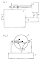
- Fig. 1 shows schematically the arrangement of a device according to the invention on a microwave device for disinfecting goods.
- Fig. 2 shows schematically the beam path within the exhaust air duct and the arrangement of the receiving units.
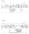
- Fig. 3 shows a block diagram of the receiving unit located in the optical beam path.
- FIG. 4 shows, analogously to FIG. 3, the receiving unit arranged outside the optical beam path.
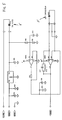
- FIG. 5 illustrates a circuit diagram relating to the light barrier with the associated preamplifier.
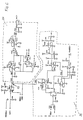
- FIG. 6 shows a circuit diagram relating to the further processing of the signal obtained from the pre-amplifier according to FIG. 5.
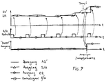
- FIG. 7 shows in the form of a diagram the relationship between the signals occurring at the individual outputs of the steam-determining branch.
- a transmitting unit 1 and two receiving units 2 and 3 are provided in an exhaust air duct 5 of a treatment room 4 of a microwave device.
- the receiving unit 3 is arranged in the optical beam path of the transmitting unit.
- the receiving unit 2 is arranged outside the optical beam path.
- the transmitting unit and the receiving units can also be provided directly in the treatment room, not shown, and it is only essential that the units mentioned are located in the exhaust air area.
- the receiving units are connected to a processor circuit 6 via corresponding lines. This processor circuit is connected via lines 9, 10 to a microwave power control unit 8, which in turn then controls the power of the magnetron (s) 7.
- the photodiode FD1 absorbs the radiation emitted by the transmitter unit and thus reduce the intensity of the signal processed in the receiver unit 3.
- the vapor particles drawn as bare rings in FIG. 2 diffract or reflect the radiation, the diffracted or reflected radiation being detected by the receiving unit 2.
- the signal supplied by the photodiode FD1 is processed in a low-noise amplifier which holds 0 volts on the photodiode FD1, so that only the photocurrent is amplified and thermal drift does not take place .
- the amplifier A1 is connected to an amplifier A1 ', which is in feedback with an integrating element I1.
- the output signal from the smoke sensor can also be influenced by the steam, namely that steam results in a slow reduction in intensity
- an automatic potential equalization is achieved by a feedback with the integration, in which the pulse-shaped signals are filtered out, so that the output of the Amplifier A1 'can never saturate.
- the signal supplied by the amplifier A1 ' is differentiated in a differentiator D1.
- Each smoke particle influences the light intensity in a pulse-like manner, whereby the differentiator separates these pulses from the overall signal, ie the steeper the pulse, the greater the output signal.
- the output signal coming from the differentiator D1 is included a reference voltage in a comparator C1 compared.
- the signal from the comparator C1 is fed via a line 9 to a microprocessor unit 6, in which this signal is processed logically.
- the reflected or deflected radiation is received in the receiving unit 2, which is located outside the optical beam path of the transmitting unit 1, by means of the photodiode FD2. If there is no steam, then this photodiode absorbs very little or no radiation, at best that radiation which is reflected by the wall of the exhaust air duct 5. The higher the amount of steam increases, the more light is reflected and the higher the signal sent to amplifier A2.
- the signal amplified by amplifier A2 passes into a further amplifier A2 ', the output of which is connected on the one hand to a comparator C2 and on the other hand to the input of a sample / hold circuit.
- sample / hold circuit The output of this sample / hold circuit is connected on the one hand to the comparator C2 and on the other hand with feedback to the amplifier A2 '.
- the increase in intensity is very slow and is evaluated by the sample / hold circuit (sample period is in the range of seconds) by constant comparison between the current and the previous value.
- the comparator C2 takes on this comparison role.
- An automatic equipotential bonding is achieved by the feedback mentioned with the amplifier A2 ′.
- the signal supplied by the comparator C2 is likewise fed to the microprocessor unit 6 via the line 10.
- the control of the microwave power then takes place via this control, specifically via the control unit 8.
- a simple light barrier which has an infrared LED 1 'and an infrared photodiode 3'.
- the measuring principle is based on a light intensity measurement, the photocurrent being regulated by the IR LED 1 'and the IR photodiode 3' so that the photocurrent is little above the dark current of the photodiode.
- the evaluation device consists of two functionally separate modules, namely the transmitter-receiver module with built-in preamplifier and the analog and digital microcontroller module, with which the actual evaluation of the signals is then carried out.
- a preamplifier is connected to the IR photodiode 3 ', which is an operational amplifier (OP) with CMOS technology, which amplifies the very small photo current.
- This amplifier is designated U2D in FIG. 5.
- the circuit represents a so-called current-voltage converter.
- the operating point (DC voltage) is held at a predetermined level by a second operational amplifier, which is designated U2A in FIG. 5, which is given by the resistors R2 and R3.
- the output signal R + D of the amplifier U2D is therefore a voltage which can easily change depending on the presence of steam and / or smoke in the measuring channel.
- the voltage is determined in the vapor and smoke-free state by the light intensity of the IR LED 1 '.
- the analog and digital module consists of a part 21, which detects the presence of steam, and the part 20, which comprises the presence of smoke.
- the R + D signal coming from the preamplifier is divided at 19, one part being fed to the part 21 determining the steam presence and the other part to the part determining the smoke presence.
- the partial signal that is used to determine the steam presence is fed to the input of a part U303 A designed as a voltage amplifier.
- the output signal of this voltage amplifier is stored on a capacitor C307 in a time interval of a few seconds (sample / hold circuit).
- the voltage supplied to the capacitor C307 is read with U303B and inverted and fed back via the inverter U303D, to the non-inverting input of U303A, so that the voltage at C307 always has the specified sample value, in this case around approximately + 4 V. .
- the + 4 V come from components U303 and Q300. If there is a change in the received light intensity due to the occurrence of steam, the voltages at the capacitor C 307 and at the output of U303A will diverge between two sample intervals. A comparator U16B is provided to evaluate this difference.
- the switching point of the capacitor that is, at what difference it indicates the presence of steam, is determined by the voltage divider R314, R315.
- the voltage at the output of the comparator U16B is therefore information about the steam presence.
- the sensitivity is due to the sample / hold time ratio and determined by the voltage divider R314, R315.
- the intensity of the IR transmitter also plays a certain role. Too high infrared radiation makes the receiver insensitive to small amounts of reflected light, ie that the voltage rise given by the presence of already small amounts of steam cannot be measured, which makes the device insensitive to the start of the occurrence of steam.
- IR radiation that is too small does not provide a reserve for the smoke detection unit, since even the slightest weakening of the light intensity means that no changes in the light intensity can be perceived, that is to say that impulse-like reductions in the intensity of light given by the impulsive passing of fumes cannot be perceived.
- the other partial signal that arises at the signal divider is processed further, this R + D signal first being passed through an RC filter R301, C300 to suppress interference signals. Then the suppressed signal is fed to an amplifier U304A, the gain of which is determined by the resistors R302 and R301 '.
- This operational amplifier has an integrator U304B as feedback, the time constant of which is defined by R303 and C301.
- the integration on the negative feedback serves as an automatic compensation for the slowly fluctuating amplitude changes that can arise from the presence of steam.
- the combination U304A and U304B can only get one pulse-shaped signal through.
- This combination is followed by a differentiating stage U304C, which has a time constant C 302 ', R307.
- This differentiation stage is followed by a peak value detector with the D300 diode and the C 304 capacitor.
- the voltage at the capacitor C304 is thus direct information about the existence of pulse-shaped signals at the output from the preamplifier, which indicates the presence of smoke particles.
- Fig. 7 shows the sequence of the individual switching stages in the form of diagrams.
- the solid signal comes from the output of amplifier A2 'according to FIG. 4 or from the output of amplifier U303A according to FIG. 6.
- the signal marked with triangles is the signal which is fed from the sample / hold element to the comparator.
- the the signal below, marked with squares, shows the time impulses of the sample / hold element and thus also the time of comparison between the sample / hold element and the value measured at the output of the amplifier.
- the sample / hold element rises depending on the course of the signal at output A2 'or U303A, the individual readjustment stages of the sample / hold element depending on the increase in the actual signal change.
- the comparator responds in such a way that it indicates the presence of steam.
- the values measured at the "steam outlet" are identified by circles in FIG. 7, the switching stage which is indicated as a single stage when a higher difference between the last sample / hold value and the measured value at output A2 'or U303A is reached , which is then responsible for switching the display device to display the steam presence.
Landscapes
- Physics & Mathematics (AREA)
- Life Sciences & Earth Sciences (AREA)
- General Life Sciences & Earth Sciences (AREA)
- General Physics & Mathematics (AREA)
- Geophysics (AREA)
- Investigating Or Analysing Materials By Optical Means (AREA)
- Apparatus For Disinfection Or Sterilisation (AREA)
- Filtering Of Dispersed Particles In Gases (AREA)
- Air Supply (AREA)
- Sampling And Sample Adjustment (AREA)
Claims (11)
- Procédé de détection de la présence de vapeur et/ou de fumée dans l'air d'échappement d'un appareil à micro-ondes de désinfection ou de stérilisation d'objets, au moyen d'une barrière photoélectrique, aussi bien l'intensité de la lumière traversante que celle de la lumière déviée et/ou réfléchie étant mesurée, caractérisé en ce qu'est employée, pour la détection de la présence de vapeur, la lumière déviée et/ou réfléchie par les particules de vapeur et, pour la détection de la présence de fumée, la réduction d'intensité pulsée, de la lumière traversant les gaz d'échappement.
- Procédé selon la revendication 1, caractérisé en ce que la lumière déviée et/ou réfléchie est détectée en même temps que la lumière traversante, le signal commun ainsi obtenu étant divisé et, ensuite, traité séparément.
- Procédé selon la revendication 1 ou 2, caractérisé en ce que le signal de la réduction d'intensité pulsée est différencié, une intégration d'équilibrage à 0 d'un amplificateur opérationnel monté en amont étant, le cas échéant, préalablement réalisée.
- Procédé selon l'une des revendications 1 à 3, caractérisé en ce que le signal dérivé du rayon dévié et/ou réfléchi est comparé avec un signal généré par un circuit échantillonneur-bloqueur.
- Procédé selon l'une des revendications 1 à 4, caractérisé en ce que l'intensité de l'émetteur de la barrière photoélectrique est réglée à une valeur seulement légèrement supérieure à la limite du courant d'obscurité du récepteur.
- Procédé selon l'une des revendications 2 à 5, caractérisé en ce que les valeurs mesurées pour le rayonnement dévié et/ou réfléchi sont mises en relation avec les valeurs mesurées pour le rayonnement direct pulsé à intensité réduite, et en ce que l'augmentation d'intensité des premières valeurs est utilisée pour déterminer la présence de vapeur.
- Dispositif de mise en oeuvre du procédé selon l'une des revendications 1 à 6, dans lequel sont présents, dans la zone d'air d'échappement d'un appareil à micro-ondes de désinfection et de stérilisation d'objets, une source de rayons et un récepteur disposé sur le trajet des rayons optiques, caractérisé en ce qu'est monté, en aval du récepteur (3′), un dispositif de division de signaux, un préamplificateur (U2D) étant, le cas échéant, monté en amont du dispositif de division de signaux, et en ce que sont montés, en aval du dispositif de division de signaux, un dispositif de détection de la fumée (20) et un dispositif de détection de la vapeur (21).
- Dispositif selon la revendication 7, caractérisé en ce que le dispositif de détection de la fumée (20) comporte un amplificateur (U304A) monté en aval du dispositif de division de signaux et un élément différenciateur (U304C) monté en aval de celui-ci.
- Dispositif selon la revendication 8, caractérisé en ce que l'amplificateur (U304A) est pourvu d'une rétroaction présentant un intégrateur (U304B), dont la constante de temps est fixée par une combinaison résistance-capacité (R303, C301).
- Dispositif selon l'une des revendications 7 à 9, caractérisé en ce que le dispositif de détection de la vapeur (21), monté en aval du dispositif de division de signaux, comprend un amplificateur de tension (U303A), un circuit échantillonneur-bloqueur (C307) et un comparateur (U16B) relié à la sortie de l'amplificateur de tension (U303A) et au circuit échantillonneur-bloqueur (C307).
- Dispositif selon la revendication 10, caractérisé en ce qu'est monté, en amont de l'entrée non inverseuse de l'amplificateur de tension (U303A), un organe inverseur (U303D), à l'aide duquel la tension prélevée à la sortie de l'amplificateur de tension (U303A) est susceptible d'être inversée et réinjectée.
Applications Claiming Priority (2)
| Application Number | Priority Date | Filing Date | Title |
|---|---|---|---|
| AT254/90 | 1990-02-06 | ||
| AT25490 | 1990-02-06 |
Publications (3)
| Publication Number | Publication Date |
|---|---|
| EP0441771A2 EP0441771A2 (fr) | 1991-08-14 |
| EP0441771A3 EP0441771A3 (en) | 1992-08-26 |
| EP0441771B1 true EP0441771B1 (fr) | 1995-04-26 |
Family
ID=3485649
Family Applications (1)
| Application Number | Title | Priority Date | Filing Date |
|---|---|---|---|
| EP91890022A Expired - Lifetime EP0441771B1 (fr) | 1990-02-06 | 1991-02-06 | Procédé pour la détection de la présence de vapeur ou de fumée dans l'air d'échappement d'un appareil pour le chauffage de matériaux et dispositif pour exécuter ce procédé |
Country Status (3)
| Country | Link |
|---|---|
| EP (1) | EP0441771B1 (fr) |
| AT (1) | ATE121849T1 (fr) |
| DE (1) | DE59105284D1 (fr) |
Families Citing this family (3)
| Publication number | Priority date | Publication date | Assignee | Title |
|---|---|---|---|---|
| DE19580796D2 (de) * | 1994-07-15 | 1996-09-26 | Baumer Electric Ag | Optischer Sensor mit Störlichtunterdrückung |
| AT403007B (de) * | 1995-07-24 | 1997-10-27 | Katschnig Helmut | Anlage zum erhitzen, desinfizieren und sterilisieren von gütern |
| CN109990989B (zh) * | 2017-12-29 | 2021-05-18 | 宁波方太厨具有限公司 | 一种挡烟板组件耐久性能测试装置及测试方法 |
Citations (1)
| Publication number | Priority date | Publication date | Assignee | Title |
|---|---|---|---|---|
| EP0287549A1 (fr) * | 1987-04-14 | 1988-10-19 | Helmut Dr. Katschnig | Dispositif pour chauffer des objets et des organismes |
Family Cites Families (4)
| Publication number | Priority date | Publication date | Assignee | Title |
|---|---|---|---|---|
| FR2181437B3 (fr) * | 1972-04-24 | 1975-06-20 | Media Messages Systemes | |
| CH595113A5 (fr) * | 1976-03-18 | 1978-01-31 | Cerberus Ag | |
| US4420257A (en) * | 1980-02-14 | 1983-12-13 | Toyo Soda Manufacturing Co., Ltd. | Laser light scattering photometer |
| SE450791B (sv) * | 1985-11-19 | 1987-07-27 | Salen & Wicander Ab | Sett och anordning for detektering av fororeningshalten i en vetska |
-
1991
- 1991-02-06 AT AT91890022T patent/ATE121849T1/de not_active IP Right Cessation
- 1991-02-06 DE DE59105284T patent/DE59105284D1/de not_active Expired - Fee Related
- 1991-02-06 EP EP91890022A patent/EP0441771B1/fr not_active Expired - Lifetime
Patent Citations (1)
| Publication number | Priority date | Publication date | Assignee | Title |
|---|---|---|---|---|
| EP0287549A1 (fr) * | 1987-04-14 | 1988-10-19 | Helmut Dr. Katschnig | Dispositif pour chauffer des objets et des organismes |
Non-Patent Citations (1)
| Title |
|---|
| EP-A1-0 287 549. * |
Also Published As
| Publication number | Publication date |
|---|---|
| ATE121849T1 (de) | 1995-05-15 |
| EP0441771A3 (en) | 1992-08-26 |
| DE59105284D1 (de) | 1995-06-01 |
| EP0441771A2 (fr) | 1991-08-14 |
Similar Documents
| Publication | Publication Date | Title |
|---|---|---|
| EP0360126B2 (fr) | Méthode d'opération d'un détecteur optique de fumée et détecteur de fumée pour la mise en oeuvre de la méthode | |
| EP0572592B1 (fr) | Detection de fibres etrangeres dans des fils | |
| DE102004004098B3 (de) | Verfahren zur Auswertung eines Streulichtsignals und Streulichtdetektor zur Durchführung des Verfahrens | |
| DE3005923A1 (de) | Photometrisches verfahren und photometrische vorrichtung zur bestimmung von reaktionsablaeufen | |
| WO2005069242A1 (fr) | Détecteur d'incendie pourvu de plusieurs volumes d'analyse | |
| DE19841475C1 (de) | Flammenüberwachungssystem und Verfahren zur Überwachung einer Flamme | |
| DE102006039670A1 (de) | Partikelerfassungsvorrichtung und Partikelerfassungsverfahren, das dafür verwendet wird | |
| CH637480A5 (de) | Vorrichtung zur messung der konzentration mindestens einer komponente eines gasgemisches und verfahren zum betrieb der vorrichtung. | |
| DE3050124T1 (de) | Self-checking photoelectric smoke detector | |
| EP0257292A1 (fr) | Dispositif opto-électronique de mesure de distance selon le principe de la mesure de délai de retour d'un écho | |
| DE69315015T2 (de) | Spektrophotometrische Methode und Spektrophotometer zur Druchführung der Methode | |
| EP0441771B1 (fr) | Procédé pour la détection de la présence de vapeur ou de fumée dans l'air d'échappement d'un appareil pour le chauffage de matériaux et dispositif pour exécuter ce procédé | |
| DE102014200243A1 (de) | Rauchmelder mit Umgebungslichterkennung | |
| EP2251847B1 (fr) | Dispositif et procédé de détection de flammes à l'aide de détecteurs | |
| DE69936402T2 (de) | Feuchtigkeitssensor mit digitaler signalverarbeitungsfilterung | |
| DE102017005386A1 (de) | Überwachungsverfahren | |
| EP1087352A1 (fr) | Détecteur optique de fumée | |
| DE69501078T2 (de) | Optisches bewegungserfassungssystem | |
| DE102008010446A1 (de) | Verfahren und optische Sensoranordnung zum Erfassen einer Messgröße eines Mediums, insbesondere zur Trübungsmessung | |
| US5220179A (en) | Method of and apparatus for detecting the presence of vapor and/or smoke in the outgoing air of a device for heating materials | |
| DE3784206T2 (de) | Gasanalysiervorrichtung. | |
| EP0880118B1 (fr) | Détecteur optique de fumée | |
| DE3042622C2 (de) | Vorrichtung zur Überwachung der Geschwindigkeit und des Durchsatzes von Strömungen | |
| DE102006023971B4 (de) | Optischer Sensor und Verfahren zum Nachweis von Personen, Tieren oder Gegenständen | |
| DE102010025929B4 (de) | Verfahren zum gepulsten Betreiben einer Lichtschranke und Lichtschranke |
Legal Events
| Date | Code | Title | Description |
|---|---|---|---|
| PUAI | Public reference made under article 153(3) epc to a published international application that has entered the european phase |
Free format text: ORIGINAL CODE: 0009012 |
|
| AK | Designated contracting states |
Kind code of ref document: A2 Designated state(s): AT BE CH DE DK ES FR GB GR IT LI LU NL SE |
|
| PUAL | Search report despatched |
Free format text: ORIGINAL CODE: 0009013 |
|
| AK | Designated contracting states |
Kind code of ref document: A3 Designated state(s): AT BE CH DE DK ES FR GB GR IT LI LU NL SE |
|
| 17P | Request for examination filed |
Effective date: 19930218 |
|
| 17Q | First examination report despatched |
Effective date: 19940308 |
|
| GRAA | (expected) grant |
Free format text: ORIGINAL CODE: 0009210 |
|
| AK | Designated contracting states |
Kind code of ref document: B1 Designated state(s): AT BE CH DE DK ES FR GB GR IT LI LU NL SE |
|
| PG25 | Lapsed in a contracting state [announced via postgrant information from national office to epo] |
Ref country code: IT Free format text: LAPSE BECAUSE OF FAILURE TO SUBMIT A TRANSLATION OF THE DESCRIPTION OR TO PAY THE FEE WITHIN THE PRE;WARNING: LAPSES OF ITALIAN PATENTS WITH EFFECTIVE DATE BEFORE 2007 MAY HAVE OCCURRED AT ANY TIME BEFORE 2007. THE CORRECT EFFECTIVE DATE MAY BE DIFFERENT FROM THE ONE RECORDED.SCRIBED TIME-LIMIT Effective date: 19950426 Ref country code: NL Free format text: LAPSE BECAUSE OF FAILURE TO SUBMIT A TRANSLATION OF THE DESCRIPTION OR TO PAY THE FEE WITHIN THE PRESCRIBED TIME-LIMIT Effective date: 19950426 Ref country code: DK Effective date: 19950426 Ref country code: ES Free format text: THE PATENT HAS BEEN ANNULLED BY A DECISION OF A NATIONAL AUTHORITY Effective date: 19950426 Ref country code: GR Free format text: LAPSE BECAUSE OF FAILURE TO SUBMIT A TRANSLATION OF THE DESCRIPTION OR TO PAY THE FEE WITHIN THE PRESCRIBED TIME-LIMIT Effective date: 19950426 Ref country code: GB Effective date: 19950426 Ref country code: BE Effective date: 19950426 |
|
| REF | Corresponds to: |
Ref document number: 121849 Country of ref document: AT Date of ref document: 19950515 Kind code of ref document: T |
|
| REF | Corresponds to: |
Ref document number: 59105284 Country of ref document: DE Date of ref document: 19950601 |
|
| PG25 | Lapsed in a contracting state [announced via postgrant information from national office to epo] |
Ref country code: SE Effective date: 19950726 |
|
| ET | Fr: translation filed | ||
| NLV1 | Nl: lapsed or annulled due to failure to fulfill the requirements of art. 29p and 29m of the patents act | ||
| GBV | Gb: ep patent (uk) treated as always having been void in accordance with gb section 77(7)/1977 [no translation filed] |
Effective date: 19950426 |
|
| PG25 | Lapsed in a contracting state [announced via postgrant information from national office to epo] |
Ref country code: LI Free format text: LAPSE BECAUSE OF NON-PAYMENT OF DUE FEES Effective date: 19960228 Ref country code: CH Free format text: LAPSE BECAUSE OF NON-PAYMENT OF DUE FEES Effective date: 19960228 |
|
| PG25 | Lapsed in a contracting state [announced via postgrant information from national office to epo] |
Ref country code: LU Free format text: LAPSE BECAUSE OF NON-PAYMENT OF DUE FEES Effective date: 19960229 |
|
| PLBE | No opposition filed within time limit |
Free format text: ORIGINAL CODE: 0009261 |
|
| STAA | Information on the status of an ep patent application or granted ep patent |
Free format text: STATUS: NO OPPOSITION FILED WITHIN TIME LIMIT |
|
| 26N | No opposition filed | ||
| REG | Reference to a national code |
Ref country code: CH Ref legal event code: PL |
|
| PGFP | Annual fee paid to national office [announced via postgrant information from national office to epo] |
Ref country code: FR Payment date: 19980227 Year of fee payment: 8 |
|
| PGFP | Annual fee paid to national office [announced via postgrant information from national office to epo] |
Ref country code: DE Payment date: 19980305 Year of fee payment: 8 |
|
| PG25 | Lapsed in a contracting state [announced via postgrant information from national office to epo] |
Ref country code: FR Free format text: LAPSE BECAUSE OF NON-PAYMENT OF DUE FEES Effective date: 19991029 |
|
| PG25 | Lapsed in a contracting state [announced via postgrant information from national office to epo] |
Ref country code: DE Free format text: LAPSE BECAUSE OF NON-PAYMENT OF DUE FEES Effective date: 19991201 |
|
| REG | Reference to a national code |
Ref country code: FR Ref legal event code: ST |
|
| PGFP | Annual fee paid to national office [announced via postgrant information from national office to epo] |
Ref country code: AT Payment date: 20000228 Year of fee payment: 10 |
|
| PG25 | Lapsed in a contracting state [announced via postgrant information from national office to epo] |
Ref country code: AT Free format text: LAPSE BECAUSE OF NON-PAYMENT OF DUE FEES Effective date: 20010206 |