EP0440271B1 - Direction à crémaillère à assistance hydraulique - Google Patents
Direction à crémaillère à assistance hydraulique Download PDFInfo
- Publication number
- EP0440271B1 EP0440271B1 EP91105995A EP91105995A EP0440271B1 EP 0440271 B1 EP0440271 B1 EP 0440271B1 EP 91105995 A EP91105995 A EP 91105995A EP 91105995 A EP91105995 A EP 91105995A EP 0440271 B1 EP0440271 B1 EP 0440271B1
- Authority
- EP
- European Patent Office
- Prior art keywords
- valve sleeve
- steering
- torsion bar
- driving pinion
- pinion
- Prior art date
- Legal status (The legal status is an assumption and is not a legal conclusion. Google has not performed a legal analysis and makes no representation as to the accuracy of the status listed.)
- Expired - Lifetime
Links
- 230000008878 coupling Effects 0.000 claims 1
- 238000010168 coupling process Methods 0.000 claims 1
- 238000005859 coupling reaction Methods 0.000 claims 1
- 238000010276 construction Methods 0.000 description 1
Images

Classifications
-
- B—PERFORMING OPERATIONS; TRANSPORTING
- B62—LAND VEHICLES FOR TRAVELLING OTHERWISE THAN ON RAILS
- B62D—MOTOR VEHICLES; TRAILERS
- B62D5/00—Power-assisted or power-driven steering
- B62D5/06—Power-assisted or power-driven steering fluid, i.e. using a pressurised fluid for most or all the force required for steering a vehicle
- B62D5/20—Power-assisted or power-driven steering fluid, i.e. using a pressurised fluid for most or all the force required for steering a vehicle specially adapted for particular type of steering gear or particular application
- B62D5/22—Power-assisted or power-driven steering fluid, i.e. using a pressurised fluid for most or all the force required for steering a vehicle specially adapted for particular type of steering gear or particular application for rack-and-pinion type
Definitions
- the invention relates to a hydraulic power steering system for motor vehicles in the rack and pinion type, according to the preamble of claim 1.
- a steering spindle is connected to a drive pinion via a driving device which allows a backlash.
- the pinion is coupled to a valve sleeve of a rotary slide valve.
- the pinion has a through hole for a rod. This rod is attached at one end to the steering shaft and at the other end in a rotary valve of a rotary valve.
- the steering spindle is also connected to the pinion via a hollow torsion bar that surrounds the rod.
- the pinion engages in a rack, the movement of which is supported by a servo device controlled by the rotary slide valve.
- the known steering has a relatively high component cost because of the additional rod and the necessary pin connection between the steering pinion and the valve sleeve. In addition, there is a considerable length in the axial direction of the steering spindle.
- the invention has for its object to provide power steering of the type mentioned with the smallest possible dimensions.
- the components that are in drive connection with one another should be accommodated in a one-piece housing with precisely defined distances.
- the drive pinion and the valve sleeve form a one-piece component.
- the steering spindle passes through the one-piece component and at the same time carries the rotary valve.
- the torsion bar also passes through a bore in the drive shaft, the torsion bar being coupled to the valve sleeve on the end face of the valve sleeve.
- the one-piece construction allows the drive pinion and the valve sleeve to be moved close together. Special, axial space-consuming connecting means between these two components can therefore be omitted.
- the steering spindle and the torsion bar can be accommodated axially compact in the one-piece component, the entire length of the one-piece component being usable for accommodating the torsion bar.
- the servo piston is provided with teeth engaging in the drive pinion, the plane of engagement of which lies opposite the plane of engagement of the rack. This measure results in a compact steering gear, which also encloses the servo motor in a common housing.
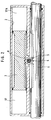
- a working cylinder 2 is arranged parallel to a rack 1.
- the rack 1 is connected to steerable wheels via tie rods, not shown.
- the toothed rack 1 and a servo piston 3 which can be displaced in the working cylinder 2 engage with their toothing, the engagement planes of which lie opposite one another, in a pinion 5 mounted on a steering spindle 4.
- the pinion 5 is made in one piece with a valve sleeve 6.
- the lower end of the steering spindle 4 is designed as a rotary valve 7, which extends into the valve sleeve 6, and together with this forms a rotary valve known per se.
- the torsion bar 8 is coupled at the lower end of the steering spindle 4 to the one-piece component (pinion 5, valve sleeve 6) by a pin 10.
- pinion 5, valve sleeve 6 As a rotation limitation one sees between the steering spindle 4 and the component 5, 6 a toothing 11 working with play.
- a housing 12 has an inlet connection 13 for a high-pressure pump 14, two working cylinder connections 15 and 15A and a return connection 16.
- the working cylinder connections 15 and 15A are connected to pressure chambers 17 and 17A of the working cylinder 2.
- the working piston 3 supports the steering movement in the opposite direction to the rack 1.
- the inlet connection 13 is connected via an annular groove 18 to axial inlet control grooves 20 of the valve sleeve 6.
- These inlet control grooves 20 cooperate in a known manner with axial control grooves 21 on the outer circumference of the rotary slide valve 7, which can connect to annular grooves 22 and 22A of the working cylinder connections 15 and 15A via invisible channels.
- axial return control grooves 23 in the Valve sleeve 6 is provided, which can be connected to a return chamber 25 via oblique bores 24 in the rotary valve 7.
- the return space 25 has a connection to a tank via the return connection 16.
- the rotary slide 7 rotates within the control path specified by the toothing 11 by a certain angular amount relative to the valve sleeve 6. This relative rotation occurs because the valve sleeve 6, which is in one piece with the pinion 5, initially still remains in its position, since the rack 1 and thus the pinion are held by the steering resistance of the wheels.
- the torsion bar 8 is elastically rotated.
- the relative rotation of the rotary valve 7 relative to the valve sleeve 6 allows pressure oil to be introduced into one of the pressure chambers 17 or 17A.
- the force of the pressure shifts the servo piston 3, which drives the rack 1 to support the hand force via the pinion 5.
- the torsion bar 8 sets the rotary slide valve 6, 7 back to the center.
Landscapes
- Engineering & Computer Science (AREA)
- Chemical & Material Sciences (AREA)
- Combustion & Propulsion (AREA)
- Transportation (AREA)
- Mechanical Engineering (AREA)
- Power Steering Mechanism (AREA)
Claims (2)
- Servo-direction hydraulique pour véhicules automobiles caractérisée en ce que:- une colonne de direction (4) actionée par un volant manuel de direction est reliée a un pignon d'entraînement (5) engrenant avec une crémaillère (1);- le pignon d'entraînement (5) est relié à une douille de soupape (6) qui entoure un distributeur rotatif (7);- la soupape du distributeur rotatif constituée de la douille de soupape (6) et du distributeur rotatif (7) comporte au milieu une barre de torsion (8) centrée qui traverse le pignon d'entraînement (5);- une extrémité de la barre de torsion (8) est reliée à la colonne de direction (4) et l'autre à la douille de soupape (6);- afin d'obtenir un jeu rotatif, comme limite de butée on utilise une denture (11) entre la colonne de direction (4) et le pignon d'entraînement,caracterisée en ce que:- le pignon d'entraînement (5) et la douille de soupape (6) forment un seul élément;- la colonne de direction (4) traverse cet élément (5, 6) et porte en même temps le distributeur rotatif (7); la barre de torsion (8) traverse un perçage de l'arbre d'entrée; et l'accouplement de la barre de torsion (8) à la douille de soupape (6) s'effectue sur sa face frontal.
- Servo-direction hydraulique suivant la revendication 1, caractérisé en ce que:
le servo-piston (3) est pourvu d'une denture engrenant avec le pignon d'entraînement (5), dont le plan d'engrènement est parallèle au plan d'engrènement de la crémaillère (1).
Applications Claiming Priority (3)
| Application Number | Priority Date | Filing Date | Title |
|---|---|---|---|
| EP8600716 | 1986-12-06 | ||
| WOPCT/EP86/00716 | 1986-12-06 | ||
| EP19870907954 EP0335886B1 (fr) | 1986-12-06 | 1987-11-27 | Servodirection hydraulique a cremaillere |
Related Parent Applications (1)
| Application Number | Title | Priority Date | Filing Date |
|---|---|---|---|
| EP87907954.9 Division | 1988-06-21 |
Publications (3)
| Publication Number | Publication Date |
|---|---|
| EP0440271A2 EP0440271A2 (fr) | 1991-08-07 |
| EP0440271A3 EP0440271A3 (en) | 1992-04-29 |
| EP0440271B1 true EP0440271B1 (fr) | 1995-07-12 |
Family
ID=8165162
Family Applications (2)
| Application Number | Title | Priority Date | Filing Date |
|---|---|---|---|
| EP19870907954 Expired - Lifetime EP0335886B1 (fr) | 1986-12-06 | 1987-11-27 | Servodirection hydraulique a cremaillere |
| EP91105995A Expired - Lifetime EP0440271B1 (fr) | 1986-12-06 | 1987-11-27 | Direction à crémaillère à assistance hydraulique |
Family Applications Before (1)
| Application Number | Title | Priority Date | Filing Date |
|---|---|---|---|
| EP19870907954 Expired - Lifetime EP0335886B1 (fr) | 1986-12-06 | 1987-11-27 | Servodirection hydraulique a cremaillere |
Country Status (3)
| Country | Link |
|---|---|
| EP (2) | EP0335886B1 (fr) |
| DE (2) | DE3740054A1 (fr) |
| WO (1) | WO1988004252A1 (fr) |
Family Cites Families (5)
| Publication number | Priority date | Publication date | Assignee | Title |
|---|---|---|---|---|
| US3102554A (en) * | 1961-10-12 | 1963-09-03 | Int Harvester Co | Power steering apparatus |
| NL301976A (fr) * | 1963-01-10 | 1900-01-01 | ||
| GB1234032A (fr) * | 1967-08-22 | 1971-06-03 | ||
| GB1237170A (en) * | 1968-07-01 | 1971-06-30 | Adwest Eng Ltd | Rack and pinion steering mechanism |
| GB2181099B (en) * | 1983-07-19 | 1987-12-23 | Ford Motor Co | Power assisted steering gear |
-
1987
- 1987-11-26 DE DE19873740054 patent/DE3740054A1/de not_active Withdrawn
- 1987-11-27 DE DE3751407T patent/DE3751407D1/de not_active Expired - Fee Related
- 1987-11-27 EP EP19870907954 patent/EP0335886B1/fr not_active Expired - Lifetime
- 1987-11-27 EP EP91105995A patent/EP0440271B1/fr not_active Expired - Lifetime
- 1987-11-27 WO PCT/EP1987/000738 patent/WO1988004252A1/fr not_active Ceased
Also Published As
| Publication number | Publication date |
|---|---|
| WO1988004252A1 (fr) | 1988-06-16 |
| EP0440271A2 (fr) | 1991-08-07 |
| EP0335886B1 (fr) | 1992-04-15 |
| DE3740054A1 (de) | 1988-06-16 |
| DE3751407D1 (de) | 1995-08-17 |
| EP0440271A3 (en) | 1992-04-29 |
| EP0335886A1 (fr) | 1989-10-11 |
Similar Documents
| Publication | Publication Date | Title |
|---|---|---|
| DE3249543C2 (fr) | ||
| EP1651502B1 (fr) | Mecanisme de direction pour automobile | |
| DE2918975C2 (de) | Hilfskraftlenkung für Kraftfahrzeuge | |
| DE3690102C2 (fr) | ||
| DE3314925C2 (fr) | ||
| DE1194718B (de) | Hydraulische Hilfskraft-Lenkvorrichtung | |
| DE2114591A1 (de) | Zahnstangenlenkgetriebe | |
| DE2719926A1 (de) | Hilfskraftlenkung fuer kraftfahrzeuge | |
| DE2353984C3 (de) | Lenkgetriebe mit Hilfskraftunterstützung, insbesondere für Kraftfahrzeuge | |
| DE2913484C2 (de) | Hydraulische Hilfskraftlenkung, insbesondere für Kraftfahrzeuge | |
| DE3150063C2 (fr) | ||
| DE1455974C3 (de) | Hydraulische Hilfskraft-Lenkvorrichtung für Kraftfahrzeuge | |
| EP0198824B1 (fr) | Servodirection hydraulique, en particulier pour vehicules a moteur | |
| DE4422551C1 (de) | Durch Servomotor unterstützte Zahnstangenlenkung | |
| DE3739848A1 (de) | Drehschieberventil fuer hydraulische hilfskraftlenkungen | |
| WO1981000239A1 (fr) | Mecanisme de commande a cremaillere | |
| DE2917435C2 (de) | Drehschiebereinrichtung zur Steuerung eines hydrostatischen Servoantriebs | |
| DE1920826A1 (de) | Druckmittelsteuereinrichtung fuer Servolenkungen,insbesondere fuer Kraftfahrzeuge | |
| DE2919051C2 (de) | Hydrostatische Hilfskraftlenkung | |
| DE1941557C3 (de) | Kraftfahrzeug-Lenkgetriebe | |
| DE2365489A1 (de) | Integrale servolenkung | |
| EP0335886B1 (fr) | Servodirection hydraulique a cremaillere | |
| EP1727724B1 (fr) | Direction assistee a superposition hydraulique des couples | |
| DE2020175C3 (de) | Steuerventil für Servo-Lenkgetriebe | |
| EP1590227B1 (fr) | Systeme de direction |
Legal Events
| Date | Code | Title | Description |
|---|---|---|---|
| PUAI | Public reference made under article 153(3) epc to a published international application that has entered the european phase |
Free format text: ORIGINAL CODE: 0009012 |
|
| 17P | Request for examination filed |
Effective date: 19910416 |
|
| AC | Divisional application: reference to earlier application |
Ref document number: 335886 Country of ref document: EP |
|
| AK | Designated contracting states |
Kind code of ref document: A2 Designated state(s): DE GB IT |
|
| PUAL | Search report despatched |
Free format text: ORIGINAL CODE: 0009013 |
|
| RAP3 | Party data changed (applicant data changed or rights of an application transferred) |
Owner name: ZF FRIEDRICHSHAFEN AKTIENGESELLSCHAFT |
|
| AK | Designated contracting states |
Kind code of ref document: A3 Designated state(s): DE GB IT |
|
| 17Q | First examination report despatched |
Effective date: 19941202 |
|
| ITF | It: translation for a ep patent filed | ||
| GRAA | (expected) grant |
Free format text: ORIGINAL CODE: 0009210 |
|
| AC | Divisional application: reference to earlier application |
Ref document number: 335886 Country of ref document: EP |
|
| AK | Designated contracting states |
Kind code of ref document: B1 Designated state(s): DE GB IT |
|
| REF | Corresponds to: |
Ref document number: 3751407 Country of ref document: DE Date of ref document: 19950817 |
|
| GBT | Gb: translation of ep patent filed (gb section 77(6)(a)/1977) |
Effective date: 19950808 |
|
| PLBE | No opposition filed within time limit |
Free format text: ORIGINAL CODE: 0009261 |
|
| STAA | Information on the status of an ep patent application or granted ep patent |
Free format text: STATUS: NO OPPOSITION FILED WITHIN TIME LIMIT |
|
| 26N | No opposition filed | ||
| PGFP | Annual fee paid to national office [announced via postgrant information from national office to epo] |
Ref country code: GB Payment date: 19961021 Year of fee payment: 10 |
|
| PG25 | Lapsed in a contracting state [announced via postgrant information from national office to epo] |
Ref country code: GB Free format text: LAPSE BECAUSE OF NON-PAYMENT OF DUE FEES Effective date: 19971127 |
|
| GBPC | Gb: european patent ceased through non-payment of renewal fee |
Effective date: 19971127 |
|
| PGFP | Annual fee paid to national office [announced via postgrant information from national office to epo] |
Ref country code: DE Payment date: 20051125 Year of fee payment: 19 |
|
| PG25 | Lapsed in a contracting state [announced via postgrant information from national office to epo] |
Ref country code: IT Free format text: LAPSE BECAUSE OF NON-PAYMENT OF DUE FEES Effective date: 20051127 |
|
| PG25 | Lapsed in a contracting state [announced via postgrant information from national office to epo] |
Ref country code: DE Free format text: LAPSE BECAUSE OF NON-PAYMENT OF DUE FEES Effective date: 20070601 |