EP0440151B1 - Method for flattening tree trunks - Google Patents
Method for flattening tree trunks Download PDFInfo
- Publication number
- EP0440151B1 EP0440151B1 EP19910101103 EP91101103A EP0440151B1 EP 0440151 B1 EP0440151 B1 EP 0440151B1 EP 19910101103 EP19910101103 EP 19910101103 EP 91101103 A EP91101103 A EP 91101103A EP 0440151 B1 EP0440151 B1 EP 0440151B1
- Authority
- EP
- European Patent Office
- Prior art keywords
- reference plane
- point
- logs
- log
- butt end
- Prior art date
- Legal status (The legal status is an assumption and is not a legal conclusion. Google has not performed a legal analysis and makes no representation as to the accuracy of the status listed.)
- Expired - Lifetime
Links
Images


Classifications
-
- B—PERFORMING OPERATIONS; TRANSPORTING
- B27—WORKING OR PRESERVING WOOD OR SIMILAR MATERIAL; NAILING OR STAPLING MACHINES IN GENERAL
- B27L—REMOVING BARK OR VESTIGES OF BRANCHES; SPLITTING WOOD; MANUFACTURE OF VENEER, WOODEN STICKS, WOOD SHAVINGS, WOOD FIBRES OR WOOD POWDER
- B27L11/00—Manufacture of wood shavings, chips, powder, or the like; Tools therefor
- B27L11/007—Combined with manufacturing a workpiece
-
- B—PERFORMING OPERATIONS; TRANSPORTING
- B27—WORKING OR PRESERVING WOOD OR SIMILAR MATERIAL; NAILING OR STAPLING MACHINES IN GENERAL
- B27B—SAWS FOR WOOD OR SIMILAR MATERIAL; COMPONENTS OR ACCESSORIES THEREFOR
- B27B1/00—Methods for subdividing trunks or logs essentially involving sawing
- B27B1/007—Methods for subdividing trunks or logs essentially involving sawing taking into account geometric properties of the trunks or logs to be sawn, e.g. curvature
-
- B—PERFORMING OPERATIONS; TRANSPORTING
- B27—WORKING OR PRESERVING WOOD OR SIMILAR MATERIAL; NAILING OR STAPLING MACHINES IN GENERAL
- B27C—PLANING, DRILLING, MILLING, TURNING OR UNIVERSAL MACHINES FOR WOOD OR SIMILAR MATERIAL
- B27C1/00—Machines for producing flat surfaces, e.g. by rotary cutters; Equipment therefor
- B27C1/02—Smoothing, i.e. working one side only
-
- Y—GENERAL TAGGING OF NEW TECHNOLOGICAL DEVELOPMENTS; GENERAL TAGGING OF CROSS-SECTIONAL TECHNOLOGIES SPANNING OVER SEVERAL SECTIONS OF THE IPC; TECHNICAL SUBJECTS COVERED BY FORMER USPC CROSS-REFERENCE ART COLLECTIONS [XRACs] AND DIGESTS
- Y10—TECHNICAL SUBJECTS COVERED BY FORMER USPC
- Y10T—TECHNICAL SUBJECTS COVERED BY FORMER US CLASSIFICATION
- Y10T83/00—Cutting
- Y10T83/525—Operation controlled by detector means responsive to work
- Y10T83/536—Movement of work controlled
Definitions
- the invention relates to a method for flattening tree trunks with a curved longitudinal center line, in which the tree trunks are conveyed in the lying position with their convex side up and their concave side down in the longitudinal direction and flattened on the concave side in the region of an earth end from below and before are measured in a position in which they lie only at end points of the concave side on a reference plane, the position of a first point of the tree trunk being determined after it has been raised above the reference plane, and the tree trunks on the end point facing away from the end of the earth when the end of the earth is continuously supported the reference plane at the end of the earth is lowered so far that the first point lies in a predetermined plane, and the tree trunks are flattened in this lowered position up to the reference plane.
- a method and a device of the type mentioned above are known from DE-OS 37 30 865.
- tree trunks that are to be processed into finished products such as squared timber, boards and the like in sawmill systems have grown strictly straight only in exceptional cases due to natural conditions.
- the tree trunks supplied generally have a curved longitudinal center line, so that this odd growth form must be taken into account when processing the tree trunks in order to obtain an optimal wood yield.
- Another possible source of error in such tree trunks is the shape of the so-called earth end, i.e. the thickening of the trunk in the transition to the root area.
- Tree trunks are sawn off as close to the ground as possible for the sake of optimal yield, so that a considerable proportion of the tree trunk length, for example one meter, widens conically progressively and thus has a considerably larger cross-section than the otherwise more or less regularly tapered rest Tree trunk. If such a tree trunk with the end of the earth now lies on a flat contact surface of a conventional transport device for sawmill systems, it would also lie very obliquely even with the longitudinal center line that would otherwise run straight, because the end of the earth with its much larger diameter allows the thicker end of the tree to stand up.
- the end of the earth is flattened on one side on the concavely curved side of the tree trunk, so that the tree trunk comes to a flatter support on a conveyor and therefore a better timber yield is achieved.
- the tree trunks are measured before flattening in such a way that the position of the first point on the concave side is determined as the point of greatest deflection after the distance from the earthed end point and after its elevation above the reference plane becomes.
- the tree trunk is then lowered so far at the end of the earth that the first point lies in the reference plane.
- the invention is therefore based on the object of developing a method and a device of the type mentioned in such a way that this wish is taken into account.
- this object is achieved according to the invention in that the first point on the convex side marks the lowest point between the highest elevation and the end of the earth, and in that the predetermined plane lies at a height above the reference plane which corresponds to the diameter of the tree trunk at the end facing away from the earth.
- the object on which the invention is based is completely achieved in this way because the abovementioned measures apply to a large number of Tree types and also with certain types of tree growth enable an even higher wood yield than is the case with the method mentioned at the beginning.
- the method according to the invention has the advantage that it is easier to carry out in practice because only two diameters have to be determined.
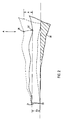
- Fig. 1 designates a tree trunk of natural growth, the longitudinal center line 10a of which is curved.
- the tree trunk 10 is arranged horizontally so that a convexly curved side 11 lies at the top and a concave curved side 12 lies at the bottom. In this position, the tree trunk 10 lies on a reference plane designated 13, which can be, for example, an upper level of a conveying device of a sawmill system.
- the thinner end of the tree trunk 10 on the left in FIG. 1 has a first point 20 and a second point 21 as end points of the thinner end and the diameter of the tree trunk 10 at the thinner end is denoted by d o .
- the tree trunk 10 lies with a third point 22 on the reference plane 13.
- a fourth point 23 marks the point of highest elevation on the convex side 11 of the tree trunk 10.
- a fifth point 26 marks the lowest point on the convex side 11 between the fourth point 23 of the highest elevation and the end of the earth 27.
- the height of the tree trunk 10 in the fifth Point 26 is denoted by h.
- the measured values d o and h can be determined using measuring devices known per se, as will be explained further below with reference to FIGS. 3 to 5.
- the tree trunk 10 In order to pre-process the tree trunk 10 in a manner that enables subsequent processing with optimum wood yield, the tree trunk 10 should now, as shown in FIG. 2 in detail, be lowered into a position in which the thinner end of the tree trunk 10 matches the first Point 20 on the reference plane 13 remains that the thicker end of the tree trunk 10 is, however, lowered so far with the earth end 27 that the fifth point 26 on the convex side 11 comes to lie at the height of the second point 21 above the reference plane 13.
- a lowering value A is determined from the previously determined measured variables do and h which corresponds to the relationship: obey.
- the tree trunk 10 is lowered approximately in the radial plane, which is defined by the fifth point 26, ie approximately in the region of the transition from the earth end 27 to the remaining tree trunk 10.
- the tree trunk 10 arrives from its starting position shown in dashed lines there, which corresponds to that of FIG. 1, into its end position drawn in solid lines.
- the seventh point 26 becomes 26 ′ and comes to lie above the reference plane 13 at the height do.
- the tree trunk flattened in this way now has an optimal contour in the horizontal direction for subsequent processing from the point of view of the best possible use of space.
- the subsequent processing can e.g. consist in a manner known per se that the flattened tree trunk 10 is now also flattened on the remaining 3 sides and then side boards or squared timber are separated from the flattened sides.
- 40 designates a first conveyor device, for example a conveyor belt, on which the Tree trunk 10 in Fig. 3 is promoted from left to right.
- the earth end 27 is conveyed ahead in the conveying direction, but this does not have to be the case, because even with a corresponding adaptation of the elements to be explained below, conveying the tree trunk 10 with the thin end ahead would also be possible without further ado.
- the tree trunk 10 passes through a light curtain 41 on its way in the first conveyor device 40, as will be explained further below with reference to FIGS. 4 and 5.
- the light curtain 41 is connected to a control unit 42, so that all the characteristic values do, di and d max already explained for FIG. 1 are supplied to the control unit 42.
- the control unit 42 determines the lowering value A from these input values and uses it to control a lifting device 43 which grips the tree trunk 10 in the region of the end of the earth.
- the tree trunk 10 'cantilever after leaving the first conveyor 40 with its earth end 27, so that the earth end 27' can be lowered by the lowering amount A when the thin end of the tree trunk 10 'is continuously supported.
- the area 30 thus reaches below the reference plane 13 and can be removed by means of a milling cutter 44 or another suitable tool. It goes without saying that instead of the lifting device 43 acting from above and drawn in in FIG. 3, a lifting device 43 'acting from below can also be used in order to lower the earth end 27' in the manner described.
- the flattened tree trunk 10 "then arrives at a second conveyor 45, from which it is fed to further processing stations, e.g. further flat milling cutters, corner milling cutters, cut-off and cross-cut saws and the like, as is known per se.
- further processing stations e.g. further flat milling cutters, corner milling cutters, cut-off and cross-cut saws and the like, as is known per se.
- the light curtain 41 preferably consists of a rectangular frame which surrounds the first conveying device 40 on all sides.
- light transmitters 50 are attached, on which light receivers 51, e.g. Facing photodiodes or the like.
- a curtain of light rays 52 is created, i.e. several, horizontally aligned and arranged one above the other, which are more or less interrupted by the contour of the trunk 10. 5 clearly shows that in this way the contour of the tree trunk 10 can also be detected in the region of the convex side 12 without contact.
Abstract
Description
Die Erfindung betrifft ein Verfahren zum Anflachen von Baumstämmen mit gebogener Längsmittellinie, bei dem die Baumstämme in liegender Position mit ihrer konvexen Seite nach oben und ihrer konkaven Seite nach unten in Längsrichtung gefördert und an der konkaven Seite im Bereich eines Erdendes von unten angeflacht werden und vor dem Anflachen in einer Position vermessen werden, in der sie nur an Endpunkten der konkaven Seite auf einer Bezugsebene aufliegen, wobei die Lage eines ersten Punktes des Baumstammes nach seiner Erhebung über der Bezugsebene bestimmt wird, und die Baumstämme bei fortwährender Auflage des Erdenden abgewandten Endpunktes auf der Bezugsebene am Erdende so weit abgesenkt werden, daß der erste Punkt in einer vorbestimmten Ebene liegt, und die Baumstämme in dieser abgesenkten lage bis zur Bezugsebene angeflacht werden.The invention relates to a method for flattening tree trunks with a curved longitudinal center line, in which the tree trunks are conveyed in the lying position with their convex side up and their concave side down in the longitudinal direction and flattened on the concave side in the region of an earth end from below and before are measured in a position in which they lie only at end points of the concave side on a reference plane, the position of a first point of the tree trunk being determined after it has been raised above the reference plane, and the tree trunks on the end point facing away from the end of the earth when the end of the earth is continuously supported the reference plane at the end of the earth is lowered so far that the first point lies in a predetermined plane, and the tree trunks are flattened in this lowered position up to the reference plane.
Ein Verfahren und eine Vorrichtung der vorstehend genannten Art sind aus der DE-OS 37 30 865 bekannt.A method and a device of the type mentioned above are known from DE-OS 37 30 865.
Bekanntlich sind Baumstämme, die in Sägewerksanlagen zu Fertigerzeugnissen, wie Kantholz, Bretter und dgl. verarbeitet werden sollen, aufgrund natürlicher Gegebenheiten nur in Ausnahmefällen streng gerade gewachsen. In der Praxis zeigt es sich, daß die angelieferten Baumstämme in aller Regel eine gebogene Längsmittellinie aufweisen, so daß diese ungerade Wuchsform bei der Bearbeitung der Baumstämme berücksichtigt werden muß, um eine optimale Holzausbeute zu erhalten. Eine weitere mögliche Fehlerquelle besteht bei derartigen Baumstämmen in der Gestalt des sogenannten Erdendes, d.h. der Verdickung des Stammes im Übergang zum Wurzelbereich. Baumstämme werden nämlich aus Gründen der optimalen Ausbeute möglichst dicht oberhalb des Erdbodens abgesägt, so daß noch ein erheblicher Anteil der Baumstammlänge, beispielsweise ein Meter, sich konisch progressiv verbreitert und dadurch einen erheblich größeren Querschnitt aufweist als der sich ansonsten mehr oder weniger regelmäßig konisch verjüngende übrige Baumstamm. Liegt nun ein derartiger Baumstamm mit Erdende auf einer planen Auflagefläche einer üblichen Transporteinrichtung von Sägewerksanlagen, so würde er auch bei ansonsten gerade verlaufender Längsmittellinie sehr schräg aufliegen, weil das Erdende mit seinem wesentlich größeren Durchmesser das dickere Baumstammende hochstehen läßt.As is well known, tree trunks that are to be processed into finished products such as squared timber, boards and the like in sawmill systems have grown strictly straight only in exceptional cases due to natural conditions. In practice, it has been shown that the tree trunks supplied generally have a curved longitudinal center line, so that this odd growth form must be taken into account when processing the tree trunks in order to obtain an optimal wood yield. Another possible source of error in such tree trunks is the shape of the so-called earth end, i.e. the thickening of the trunk in the transition to the root area. Tree trunks are sawn off as close to the ground as possible for the sake of optimal yield, so that a considerable proportion of the tree trunk length, for example one meter, widens conically progressively and thus has a considerably larger cross-section than the otherwise more or less regularly tapered rest Tree trunk. If such a tree trunk with the end of the earth now lies on a flat contact surface of a conventional transport device for sawmill systems, it would also lie very obliquely even with the longitudinal center line that would otherwise run straight, because the end of the earth with its much larger diameter allows the thicker end of the tree to stand up.
Ist nun ein Baumstamm gleichzeitig ungerade gewachsen und mit einem stark ausgebildeten Erdende versehen, so addieren sich diese Fehler möglicherweise und es ist schwierig, den Baumstamm der Bearbeitung in einer Position zuzuführen, in der eine optimale Holzausbeute gewährleistet ist.If a tree trunk has grown oddly at the same time and has a well-formed earth end, these errors may add up and it is difficult to feed the tree trunk into a position in which an optimal wood yield is guaranteed.
Aus der DE-PS 32 44 393 ist es in diesem Zusammenhang bekannt, den Baumstamm an seinem in Stammlängsrichtung konkav gekrümmten Mantelflächenabschnitt wenigstens teilweise an seinem Erdende in einer Ebene anzuflachen, die etwa parallel zu einer die beiden Stammenden am anderen in Längsrichtung konvex gekrümmten Mantelflächenabschnitt des Stammes tangierenden Ebene liegt.In this context, it is known from DE-PS 32 44 393 to at least partially flatten the tree trunk on its lateral surface section concavely curved in the longitudinal direction of the trunk at its earth end in a plane which is approximately parallel to one of the two trunk ends on the other in the longitudinal direction with a convex curved lateral surface section Tribal tangent plane.
Bei dem bekannten Verfahren bzw. der bekannten Vorrichtung wird also das Erdende auf der konkav gekrümmten Seite des Baumstammes einseitig angeflacht, so daß der Baumstamm in eine flachere Auflage auf einer Fördereinrichtung kommt und daher eine bessere Holzausbeute erzielt wird.In the known method or the known device, the end of the earth is flattened on one side on the concavely curved side of the tree trunk, so that the tree trunk comes to a flatter support on a conveyor and therefore a better timber yield is achieved.
Es hat sich jedoch in der Praxis gezeigt, daß das eingangs genannte Verfahren bzw. die zugehörige Vorrichtung insbesondere bei sehr stark gekrümmten Baumstämmen keine optimale Holzausbeute ergibt, so daß auch weiterhin das Bedürfnis besteht, die Positionierung bzw. Vorbearbeitung der Baumstämme so weiterzuentwickeln, daß auch bei sehr stark gekrümmten Baumstämmen eine optimale Holzausbeute gewährleistet ist.However, it has been shown in practice that the method mentioned above or the associated device, in particular in the case of very strongly curved tree trunks, does not result in optimal wood yield, so that there is still a need to further develop the positioning or preprocessing of the tree trunks in such a way that also optimal tree yield is guaranteed with very strongly curved tree trunks.
Bei dem aus der eingangs genannten DE-OS 37 30 865 bekannten Verfahren werden die Baumstämme vor dem Anflachen derart vermessen, daß auf der konkaven Seite die Lage des ersten Punktes als Punkt größter Durchbiegung nach Abstand vom erdendigen Endpunkt sowie nach seiner Erhebung über der Bezugsebene bestimmt wird. Der Baumstamm wird dann am Erdende so weit abgesenkt, daß der erste Punkt in der Bezugsebene liegt.In the method known from the aforementioned DE-OS 37 30 865, the tree trunks are measured before flattening in such a way that the position of the first point on the concave side is determined as the point of greatest deflection after the distance from the earthed end point and after its elevation above the reference plane becomes. The tree trunk is then lowered so far at the end of the earth that the first point lies in the reference plane.
Obwohl das bekannte Verfahren in vielen Fällen mit Vorteil angewendet werden kann, gibt es doch auch Fälle, in denen bei bestimmten Baumarten oder bei bestimmten typischen Arten des Baumwuchses noch bessere Ergebnisse wünschenswert sind.Although the known method can be used with advantage in many cases, there are also cases in which even better results are desirable for certain types of tree or for certain typical types of tree growth.
Der Erfindung liegt daher die Aufgabe zugrunde, eine Verfahren und eine Vorrichtung der eingangs gennanten Art dahingehend weiterzubilden, daß diesem Wunsche Rechnung getragen wird.The invention is therefore based on the object of developing a method and a device of the type mentioned in such a way that this wish is taken into account.
Gemäß dem eingangs genannten Verfahren wird diese Aufgabe erfindungsgemäß dadurch gelöst, daß der erste Punkt auf der konvexen Seite den niedrigsten Punkt zwischen der höchsten Erhebung und dem Erdende markiert, und daß die vorbestimmte Ebene in einer Höhe über der Bezugsebene liegt, die dem Durchmesser des Baumstammes am erdendenabgewandten Ende entspricht.According to the method mentioned in the introduction, this object is achieved according to the invention in that the first point on the convex side marks the lowest point between the highest elevation and the end of the earth, and in that the predetermined plane lies at a height above the reference plane which corresponds to the diameter of the tree trunk at the end facing away from the earth.
Die der Erfindung zugrundeliegende Aufgabe wird auf diese Weise vollkommen gelöst, weil die vorgenannten Maßnahmen bei einer Vielzahl von Baumarten und auch bei bestimmten Arten eines Baumwuchses eine noch höhere Holzausbeute ermöglichen, als dies nach dem eingangs genannten Verfahren der Fall ist. Darüberhinaus hat das erfindungsgemäße Verfahren den Vorteil, daß es in der Praxis leichter durchzuführen ist, weil lediglich zwei Durchmesser bestimmt werden müssen.The object on which the invention is based is completely achieved in this way because the abovementioned measures apply to a large number of Tree types and also with certain types of tree growth enable an even higher wood yield than is the case with the method mentioned at the beginning. In addition, the method according to the invention has the advantage that it is easier to carry out in practice because only two diameters have to be determined.
Weitere Vorteile ergeben sich aus der Beschreibung und der beigefügten Zeichnung.Further advantages result from the description and the attached drawing.
Es versteht sich, daß die vorstehend genannten und die nachstehend noch erläuterten Merkmale nicht nur in der jeweils angegebenen Kombination sondern auch in anderen Kombinationen oder in Alleinstellung verwendbar sind, ohne den Rahmen der vorliegenden Erfindung zu verlassen.It goes without saying that the features mentioned above and those yet to be explained below can be used not only in the respectively specified combination but also in other combinations or on their own without departing from the scope of the present invention.
Ausführungsbeispiele der Erfindung sind in der Zeichnung dargestellt und werden in der nachfolgenden Beschreibung näher erläutert. Es zeigen:
- Fig. 1 eine Seitenansicht eines ungerade gewachsenen Baumstammes mit ausgeprägtem Erdende sowie den im Rahmen der vorliegenden Erfindung interessierenden Meßpunkten mit ihren Koordinaten;
- Fig. 2 den Baumstamm der Fig. 1, jedoch in einer zu einer Bezugsebene erfindungsgemäß einseitig abgesenkten Stellung;
- Fig. 3 eine äußerst schematisierte Seitenansicht einer Vorrichtung zur Durchführung des erfindungsgemäßen Verfahrens;
- Fig. 4 und 5 Ansichten in Richtung der Ebene IV-V-IV-V der Fig. 3 für zwei unterschiedliche Förderpositionen von Baumstämmen.
- Figure 1 is a side view of an odd tree trunk with a pronounced end of the earth and the measuring points of interest in the context of the present invention with their coordinates.
- FIG. 2 shows the tree trunk of FIG. 1, but in a position lowered on one side according to the invention with respect to a reference plane;
- 3 shows an extremely schematic side view of a device for carrying out the method according to the invention;
- 4 and 5 views in the direction of the plane IV-V-IV-V of FIG. 3 for two different conveying positions of tree trunks.
In Fig. 1 bezeichnet 10 insgesamt einen Baumstamm von natürlichem Wuchs, dessen Längsmittellinie 10a gebogen verläuft.In Fig. 1, 10 designates a tree trunk of natural growth, the
Der Baumstamm 10 ist liegend angeordnet, so daß eine konvex gekrümmte Seite 11 oben und eine konkav gekrümmte Seite 12 unten liegt. Der Baumstamm 10 liegt in dieser Position auf einer mit 13 bezeichneten Bezugsebene auf, die beispielsweise eine obere Ebene einer Fördereinrichtung einer Sägewerksanlage sein kann.The
Das in Fig. 1 linke, dünnere Ende des Baumstammes 10 weist einen ersten Punkt 20 und einen zweiten Punkt 21 als Endpunkte des dünneren Endes auf und der Durchmesser des Baumstammes 10 am dünneren Ende ist mit do bezeichnet. Am gegenüberliegenden dickeren Stammende liegt der Baumstamm 10 mit einem dritten Punkt 22 auf der Bezugsebene 13 auf. Ein vierter Punkt 23 markiert den Punkt höchster Erhebung auf der konvexen Seite 11 des Baumstammes 10. Ein fünfter Punkt 26 markiert auf der konvexen Seite 11 den niedrigsten Punkt zwischen dem vierten Punkt 23 höchster Erhebung und dem Erdende 27. Die Höhe des Baumstammes 10 im fünften Punkt 26 wird mit h bezeichnet.The thinner end of the
Die Meßwerte do und h lassen sich mit an sich bekannten Meßeinrichtungen bestimmen, wie dies weiter unten zu den Fig. 3 bis 5 noch erläutert werden wird.The measured values d o and h can be determined using measuring devices known per se, as will be explained further below with reference to FIGS. 3 to 5.
Um den Baumstamm 10 in einer Weise vorzubearbeiten, die ein nachfolgendes Bearbeiten mit optimaler Holzausbeute ermöglicht, soll nun der Baumstamm 10, wie dies Fig. 2 im einzelnen zeigt, in eine Position abgesenkt werden, bei der das dünnere Ende des Baumstammes 10 mit dem ersten Punkt 20 auf der Bezugsebene 13 verbleibt, daß dickere Ende des Baumstammes 10 mit dem Erdende 27 jedoch so weit abgesenkt wird, daß der fünfte Punkt 26 auf der konvexen Seite 11 in der Höhe des zweiten Punktes 21 über der Bezugsebene 13 zu liegen kommt.In order to pre-process the
Um dies zu erreichen, wird aus den bereits genannten ermittelten Meßgrößen do, und h ein Absenkwert A bestimmt, der der Beziehung:![]()
![]()
Wie Fig. 2 zeigt, gelangt der Baumstamm 10 aus seiner dort gestrichelt eingezeichneten Ausgangsstellung, die derjenigen der Fig. 1 entspricht, in seine durchgezogen eingezeichnete Endstellung. Der siebte Punkt 26 wird zu 26' und kommt in der Höhe do oberhalb der Bezugsebene 13 zu liegen.As FIG. 2 shows, the
In dieser abgesenkten Position wird der Baumstamm 10 nun von unten her bis zur Bezugsebene 13 angeflacht, so daß der in Fig. 2 mit 30 bezeichnete und dort schraffiert eingezeichnete Bereich abgespant oder abgesägt wird.In this lowered position, the
Der auf diese Weise angeflachte Baumstamm hat nun in horizontaler Richtung eine für eine nachfolgende Bearbeitung unter dem Gesichtspunkt der bestmöglichen Raumausnutzung optimale Kontur. Die nachfolgende Bearbeitung kann z.B. in an sich bekannter Weise darin bestehen, daß der angeflachte Baumstamm 10 nunmehr auch auf den übrigen 3 Seiten angeflacht wird und dann Seitenbretter oder Kanthölzer von den angeflachten Seiten abgetrennt werden.The tree trunk flattened in this way now has an optimal contour in the horizontal direction for subsequent processing from the point of view of the best possible use of space. The subsequent processing can e.g. consist in a manner known per se that the
Bei dem in Fig. 3 dargestellten Ausführungsbeispiel einer bekannten Vorrichtung, die auch zur Durchführung des Verfahrens verwendet werden kann, wie es zuvor anhand der Fig. 1 und 2 erläutert wurde, bezeichnet 40 eine erste Fördereinrichtung, beispielsweise eine Förderband, auf dem der Baumstamm 10 in Fig. 3 von links nach rechts gefördert wird. Das Erdende 27 wird dabei in Förderrichtung voraus gefördert, dies muß jedoch nicht so sein, weil auch bei entsprechender Anpassung der nachstehend noch zu erläuternden Elemente auch eine Förderung des Baumstammes 10 mit dem dünnen Ende voraus ohne weiteres möglich wäre.In the exemplary embodiment of a known device shown in FIG. 3, which can also be used to carry out the method, as was explained above with reference to FIGS. 1 and 2, 40 designates a first conveyor device, for example a conveyor belt, on which the
Der Baumstamm 10 durchläuft auf seinem Weg in der ersten Fördereinrichtung 40 einen Lichtvorhang 41, wie er weiter unten zu den Fig. 4 und 5 noch erläutert werden wird. Der Lichtvorhang 41 ist an ein Steuergerät 42 angeschlossen, so daß alle zu Fig. 1 bereits erläuterten Kennwerte do, di und dmax dem Steuergerät 42 zugeführt werden. Das Steuergerät 42 ermittelt aus diesen Eingangswerten den Absenkwert A und steuert mit diesem eine Hubeinrichtung 43, die den Baumstamm 10 im Bereich des Erdendes ergreift. Wie in Fig. 3 eingezeichnet, kragt der Baumstamm 10' nach Verlassen der ersten Fördereinrichtung 40 mit seinem Erdende 27 frei aus, so daß bei fortwährender Auflage des dünnen Endes des Baumstammes 10' das Erdende 27' um den Absenkbetrag A abgesenkt werden kann. Der Bereich 30 gelangt somit unterhalb der Bezugsebene 13 und kann mittels eines Fräsers 44 oder eines anderen geeigneten Werkzeuges entfernt werden. Es versteht sich, daß hierzu statt der in Fig. 3 eingezeichneten, von oben wirkenden Hubeinrichtung 43 auch eine von unten wirkende Hubeinrichtung 43' verwendet werden kann, um das Erdende 27' in der beschriebenen Weise abzusenken.The
Der angeflachte Baumstamm 10" gelangt dann auf eine zweite Fördereinrichtung 45, von der er weiteren Bearbeitungsstationen, z.B. weiteren Anflachfräsern, Eckenfräsern, Trenn- und Kappsägen und dgl. zugeführt wird, wie dies an sich bekannt ist.The
Die Fig. 4 und 5 zeigen in zwei Positionen den Baumstamm 10 beim Durchfahren des Lichtvorhanges 41. Man erkennt, daß der Lichtvorhang 41 bevorzugt aus einem rechteckigen Rahmen besteht, der die erste Fördereinrichtung 40 allseits umschließt. In einem vertikalen Schenkel des Rahmens sind Lichtsender 50 angebracht, denen auf dem anderen vertikalen Schenkel Lichtempfänger 51, z.B. Fotodioden oder dgl. gegenüberstehen. Auf diese Weise entsteht ein Vorhang von Lichtstrahlen 52, d.h. mehrere, horizontal ausgerichtete und übereinander angeordnete Lichtschranken, die von der Kontur des Baumstammes 10 mehr oder weniger unterbrochen werden. Man erkennt aus Fig. 5 deutlich, daß auf diese Weise die Kontur des Baumstammes 10 auch im Bereich der konvexen Seite 12 berührungslos erfaßt werden kann.4 and 5 show the
Bei der Erläuterung der Vorrichtung gemäß den Fig. 3 bis 5 ist noch hinzuzufügen, daß die Hubeinrichtung 43 bzw. 43' in der in den Fig. 1 und 2 mit A eingezeichneten Absenkebene mit dem fünften Punkt 26 angreifen kann, jedoch keineswegs angreifen muß, weil selbstverständlich auch ein Absenken in der durch den dritten Punkt 22 definierten Radialebene oder auch in einer anderen Radialebene möglich ist, wobei dann die angegebene Beziehung für den Absenkwert A entsprechend anzupassen wäre.In the explanation of the device according to FIGS. 3 to 5, it should also be added that the
Claims (1)
Applications Claiming Priority (2)
| Application Number | Priority Date | Filing Date | Title |
|---|---|---|---|
| DE4003023 | 1990-02-02 | ||
| DE19904003023 DE4003023C1 (en) | 1990-02-02 | 1990-02-02 |
Publications (3)
| Publication Number | Publication Date |
|---|---|
| EP0440151A2 EP0440151A2 (en) | 1991-08-07 |
| EP0440151A3 EP0440151A3 (en) | 1992-04-08 |
| EP0440151B1 true EP0440151B1 (en) | 1994-10-05 |
Family
ID=6399244
Family Applications (1)
| Application Number | Title | Priority Date | Filing Date |
|---|---|---|---|
| EP19910101103 Expired - Lifetime EP0440151B1 (en) | 1990-02-02 | 1991-01-29 | Method for flattening tree trunks |
Country Status (5)
| Country | Link |
|---|---|
| US (1) | US5111862A (en) |
| EP (1) | EP0440151B1 (en) |
| AT (1) | ATE112515T1 (en) |
| CA (1) | CA2035310C (en) |
| DE (2) | DE4003023C1 (en) |
Families Citing this family (3)
| Publication number | Priority date | Publication date | Assignee | Title |
|---|---|---|---|---|
| DE10342903B4 (en) * | 2003-09-17 | 2006-03-09 | Siempelkamp Maschinen- Und Anlagenbau Gmbh & Co. Kg | Scattering bunker with a discharge device for spreading grit |
| DE102004037268A1 (en) * | 2004-07-31 | 2006-03-23 | Hollmann Sondermaschinen Gmbh | Elongated wood or timber unit measuring procedure, involves measuring timber unit in passage in contact-less manner with measuring device that measures progression of side that turns away from stopper |
| CA2545787C (en) | 2005-05-05 | 2009-07-14 | Centre De Recherche Industrielle Du Quebec | System and method of monitoring the quality of cutting |
Family Cites Families (9)
| Publication number | Priority date | Publication date | Assignee | Title |
|---|---|---|---|---|
| US3456774A (en) * | 1967-05-02 | 1969-07-22 | Weyerhaeuser Co | Method and apparatus for aligning and transferring logs |
| CA1018868A (en) * | 1975-11-26 | 1977-10-11 | Macmillan Bloedel Limited | Method and apparatus for aligning logs |
| FI67317C (en) * | 1980-11-14 | 1985-03-11 | Ahlstroem Oy | ANORDINATION FOR THE PURPOSE OF SYNTHETICS AND BLOCKING |
| DE3244393C1 (en) * | 1982-12-01 | 1984-03-01 | Wurster u. Dietz GmbH u. Co Maschinenfabrik, 7400 Tübingen | Process for the production of wood products processed on all sides, and device for carrying out the process |
| DE3419212C1 (en) * | 1984-05-23 | 1988-11-10 | Jenkner, Erwin, 7261 Gechingen | Process for trimming and dividing boards with raw edges, such as forest edges, and device for carrying out the process |
| FR2602993A1 (en) * | 1986-08-22 | 1988-02-26 | Bocquet Expl Bureau Etu Indles | METHOD AND DEVICE FOR MEASURING AND POSITIONING A PIECE OF WOOD IN A WOODEN MACHINE OF THE DELIGNING TYPE |
| US4839816A (en) * | 1987-06-02 | 1989-06-13 | Cattrall Thomas J | Lumber cutting system |
| US4774988A (en) * | 1987-09-11 | 1988-10-04 | Weyerhaeuser Company | Method for measuring edge profile of an elongated member |
| DE3730865A1 (en) * | 1987-09-15 | 1989-03-30 | Wurster & Dietz Maschf | Method for flattening tree trunks (clear boles) and apparatus for carrying out the method |
-
1990
- 1990-02-02 DE DE19904003023 patent/DE4003023C1/de not_active Expired - Fee Related
-
1991
- 1991-01-29 DE DE59103142T patent/DE59103142D1/en not_active Expired - Fee Related
- 1991-01-29 EP EP19910101103 patent/EP0440151B1/en not_active Expired - Lifetime
- 1991-01-29 AT AT91101103T patent/ATE112515T1/en not_active IP Right Cessation
- 1991-01-30 CA CA 2035310 patent/CA2035310C/en not_active Expired - Fee Related
- 1991-02-01 US US07/649,040 patent/US5111862A/en not_active Expired - Fee Related
Also Published As
| Publication number | Publication date |
|---|---|
| ATE112515T1 (en) | 1994-10-15 |
| DE59103142D1 (en) | 1994-11-10 |
| DE4003023C1 (en) | 1991-09-05 |
| EP0440151A2 (en) | 1991-08-07 |
| CA2035310C (en) | 1994-10-04 |
| EP0440151A3 (en) | 1992-04-08 |
| CA2035310A1 (en) | 1991-08-03 |
| US5111862A (en) | 1992-05-12 |
Similar Documents
| Publication | Publication Date | Title |
|---|---|---|
| CH639892A5 (en) | METHOD AND DEVICE FOR THE CHIPING DISASSEMBLY OF TREE TRUNKS IN ALL-SIDED WOODEN PRODUCTS, LIKE BOARDS AND QUANTITY. | |
| DE2703222A1 (en) | DEVICE FOR SAWING LUMBER WITH CURVED CUT | |
| DE3244393C1 (en) | Process for the production of wood products processed on all sides, and device for carrying out the process | |
| DE3720169A1 (en) | SAWING DEVICE | |
| DE2605987C3 (en) | Method and device for sawing wood | |
| DE2920543A1 (en) | METHOD AND DEVICE FOR PROCESSING ROUND WOOD TO LUMBER | |
| EP0440151B1 (en) | Method for flattening tree trunks | |
| AT397224B (en) | METHOD AND DEVICE FOR PRODUCING SQUARE EDGE FROM TREE TRUNKS OD. DGL. | |
| DE3730865C2 (en) | ||
| DE3623235C2 (en) | ||
| CH683828A5 (en) | A method for producing timber from logs or modeling, and apparatus for performing the method. | |
| WO1988000517A1 (en) | Process and device for cutting up tree trunks into wood products without shavings | |
| DE3347584C2 (en) | ||
| DE3514892C1 (en) | Method and device for cutting timber, in particular for dividing by chip removal tree trunks provided with construction edges | |
| EP1592538A1 (en) | Method and processing line for dissecting logs | |
| DE19929355A1 (en) | Trunk timber sawing line including trunk anglers comprises three stations with horizontal tools in first two and angled in third to give multi-faced product. | |
| EP1365899A2 (en) | Method and device for reducing round timber that is bent in one plane to wood products | |
| EP0785051A1 (en) | Method and device for cutting logs | |
| EP3036074B1 (en) | Device for cutting planks and beams | |
| DE102011054165B4 (en) | Method for producing wedge boards | |
| DE19509653C1 (en) | Parquet strip mfg. process | |
| DE202011051518U1 (en) | Device for producing wedge boards | |
| DE3418223C2 (en) | ||
| EP1648668B1 (en) | Method and device for breaking down conical tree trunks | |
| AT523679A2 (en) | Process for dividing a tree trunk and sawing system for carrying out the process |
Legal Events
| Date | Code | Title | Description |
|---|---|---|---|
| PUAI | Public reference made under article 153(3) epc to a published international application that has entered the european phase |
Free format text: ORIGINAL CODE: 0009012 |
|
| AK | Designated contracting states |
Kind code of ref document: A2 Designated state(s): AT DE FR SE |
|
| PUAL | Search report despatched |
Free format text: ORIGINAL CODE: 0009013 |
|
| AK | Designated contracting states |
Kind code of ref document: A3 Designated state(s): AT DE FR SE |
|
| 17P | Request for examination filed |
Effective date: 19920714 |
|
| 17Q | First examination report despatched |
Effective date: 19940301 |
|
| GRAA | (expected) grant |
Free format text: ORIGINAL CODE: 0009210 |
|
| AK | Designated contracting states |
Kind code of ref document: B1 Designated state(s): AT DE FR SE |
|
| REF | Corresponds to: |
Ref document number: 112515 Country of ref document: AT Date of ref document: 19941015 Kind code of ref document: T |
|
| REF | Corresponds to: |
Ref document number: 59103142 Country of ref document: DE Date of ref document: 19941110 |
|
| ET | Fr: translation filed | ||
| EAL | Se: european patent in force in sweden |
Ref document number: 91101103.9 |
|
| PLBE | No opposition filed within time limit |
Free format text: ORIGINAL CODE: 0009261 |
|
| STAA | Information on the status of an ep patent application or granted ep patent |
Free format text: STATUS: NO OPPOSITION FILED WITHIN TIME LIMIT |
|
| 26N | No opposition filed | ||
| PGFP | Annual fee paid to national office [announced via postgrant information from national office to epo] |
Ref country code: AT Payment date: 20011228 Year of fee payment: 12 |
|
| PG25 | Lapsed in a contracting state [announced via postgrant information from national office to epo] |
Ref country code: AT Free format text: LAPSE BECAUSE OF NON-PAYMENT OF DUE FEES Effective date: 20030129 |
|
| PGFP | Annual fee paid to national office [announced via postgrant information from national office to epo] |
Ref country code: DE Payment date: 20090224 Year of fee payment: 19 |
|
| PGFP | Annual fee paid to national office [announced via postgrant information from national office to epo] |
Ref country code: SE Payment date: 20090114 Year of fee payment: 19 |
|
| PGFP | Annual fee paid to national office [announced via postgrant information from national office to epo] |
Ref country code: FR Payment date: 20090115 Year of fee payment: 19 |
|
| EUG | Se: european patent has lapsed | ||
| REG | Reference to a national code |
Ref country code: FR Ref legal event code: ST Effective date: 20100930 |
|
| PG25 | Lapsed in a contracting state [announced via postgrant information from national office to epo] |
Ref country code: FR Free format text: LAPSE BECAUSE OF NON-PAYMENT OF DUE FEES Effective date: 20100201 |
|
| PG25 | Lapsed in a contracting state [announced via postgrant information from national office to epo] |
Ref country code: DE Free format text: LAPSE BECAUSE OF NON-PAYMENT OF DUE FEES Effective date: 20100803 |
|
| PG25 | Lapsed in a contracting state [announced via postgrant information from national office to epo] |
Ref country code: SE Free format text: LAPSE BECAUSE OF NON-PAYMENT OF DUE FEES Effective date: 20100130 |