EP0440123B1 - Dispositif pour la transmission de signaux dans un trou de forage - Google Patents
Dispositif pour la transmission de signaux dans un trou de forage Download PDFInfo
- Publication number
- EP0440123B1 EP0440123B1 EP19910101043 EP91101043A EP0440123B1 EP 0440123 B1 EP0440123 B1 EP 0440123B1 EP 19910101043 EP19910101043 EP 19910101043 EP 91101043 A EP91101043 A EP 91101043A EP 0440123 B1 EP0440123 B1 EP 0440123B1
- Authority
- EP
- European Patent Office
- Prior art keywords
- tubes
- drill line
- electrically
- electrically conductive
- fixed
- Prior art date
- Legal status (The legal status is an assumption and is not a legal conclusion. Google has not performed a legal analysis and makes no representation as to the accuracy of the status listed.)
- Expired - Lifetime
Links
- 238000005553 drilling Methods 0.000 claims description 14
- 125000006850 spacer group Chemical group 0.000 claims description 13
- 230000005540 biological transmission Effects 0.000 claims description 8
- 239000004020 conductor Substances 0.000 claims description 7
- 238000003780 insertion Methods 0.000 claims description 3
- 230000037431 insertion Effects 0.000 claims description 3
- 239000004519 grease Substances 0.000 claims description 2
- 230000006698 induction Effects 0.000 claims description 2
- 239000000463 material Substances 0.000 claims 5
- 239000002184 metal Substances 0.000 claims 1
- 238000005259 measurement Methods 0.000 description 4
- 238000009434 installation Methods 0.000 description 3
- 239000012811 non-conductive material Substances 0.000 description 3
- 239000004033 plastic Substances 0.000 description 3
- 239000011248 coating agent Substances 0.000 description 2
- 238000000576 coating method Methods 0.000 description 2
- 238000010292 electrical insulation Methods 0.000 description 2
- 238000011010 flushing procedure Methods 0.000 description 2
- 238000009413 insulation Methods 0.000 description 2
- 230000008054 signal transmission Effects 0.000 description 2
- RYGMFSIKBFXOCR-UHFFFAOYSA-N Copper Chemical compound [Cu] RYGMFSIKBFXOCR-UHFFFAOYSA-N 0.000 description 1
- 238000006243 chemical reaction Methods 0.000 description 1
- 229910052802 copper Inorganic materials 0.000 description 1
- 239000010949 copper Substances 0.000 description 1
- 238000005520 cutting process Methods 0.000 description 1
- 239000003822 epoxy resin Substances 0.000 description 1
- 230000003203 everyday effect Effects 0.000 description 1
- 230000002349 favourable effect Effects 0.000 description 1
- 230000001771 impaired effect Effects 0.000 description 1
- 239000007769 metal material Substances 0.000 description 1
- 238000000034 method Methods 0.000 description 1
- 229920000647 polyepoxide Polymers 0.000 description 1
- 238000007789 sealing Methods 0.000 description 1
Images
Classifications
-
- H—ELECTRICITY
- H01—ELECTRIC ELEMENTS
- H01R—ELECTRICALLY-CONDUCTIVE CONNECTIONS; STRUCTURAL ASSOCIATIONS OF A PLURALITY OF MUTUALLY-INSULATED ELECTRICAL CONNECTING ELEMENTS; COUPLING DEVICES; CURRENT COLLECTORS
- H01R4/00—Electrically-conductive connections between two or more conductive members in direct contact, i.e. touching one another; Means for effecting or maintaining such contact; Electrically-conductive connections having two or more spaced connecting locations for conductors and using contact members penetrating insulation
- H01R4/58—Electrically-conductive connections between two or more conductive members in direct contact, i.e. touching one another; Means for effecting or maintaining such contact; Electrically-conductive connections having two or more spaced connecting locations for conductors and using contact members penetrating insulation characterised by the form or material of the contacting members
- H01R4/60—Connections between or with tubular conductors
-
- E—FIXED CONSTRUCTIONS
- E21—EARTH OR ROCK DRILLING; MINING
- E21B—EARTH OR ROCK DRILLING; OBTAINING OIL, GAS, WATER, SOLUBLE OR MELTABLE MATERIALS OR A SLURRY OF MINERALS FROM WELLS
- E21B17/00—Drilling rods or pipes; Flexible drill strings; Kellies; Drill collars; Sucker rods; Cables; Casings; Tubings
- E21B17/003—Drilling rods or pipes; Flexible drill strings; Kellies; Drill collars; Sucker rods; Cables; Casings; Tubings with electrically conducting or insulating means
-
- E—FIXED CONSTRUCTIONS
- E21—EARTH OR ROCK DRILLING; MINING
- E21B—EARTH OR ROCK DRILLING; OBTAINING OIL, GAS, WATER, SOLUBLE OR MELTABLE MATERIALS OR A SLURRY OF MINERALS FROM WELLS
- E21B17/00—Drilling rods or pipes; Flexible drill strings; Kellies; Drill collars; Sucker rods; Cables; Casings; Tubings
- E21B17/18—Pipes provided with plural fluid passages
Definitions
- the invention relates to a device for, in particular, shaft drilling with a drill string, which comprises inner tubes which delimit inner flow spaces and which enclose outer tubes with spacing to form outer flow spaces, according to the preamble of claim 1.
- Devices of the aforementioned type with a drill string of double-walled drill pipes to be attached to one another are used, for example, for shaft drilling, the double-walled drill pipe comprising an outer pipe and an inner pipe and a flushing medium generally being pumped to the bottom of the hole in the annular space between the inner pipe and the outer pipe, past the drill head can flow into the inner flow space bounded by the inner pipe and can convey the cuttings to the surface through the inner flow space.
- drilling strings with such double-walled drilling pipes information is to be acquired in the course of the drilling process and is to be passed on electrically to the earth's surface for conversion into control signals, special cables for the electrical transmission of Provide measurement and control signals.
- EP-A-0 257 744 discloses a drilling device with a drill string which has an inner tube and an outer tube.
- the inner and outer tubes are spaced apart and held together by spacer elements.
- Special line elements are provided for the transmission of signals from the bottom of the borehole to the surface of the earth.
- a line element is arranged at a distance from the inner tube and the outer tube, so that flow spaces are created for a medium which in turn has to take care of insulation of the line element.
- the line element is provided with an outer insulation and is arranged like a segment of a circle between the inner tube and the outer tube.
- the design of the device according to the invention enables the transmission of measurement and control signals and also of energy between the surface of the earth or the mouth of the borehole and the bottom of the borehole in a wear-resistant manner, without the need for transmission cables which are particularly susceptible to faults.
- the mutually insulated inner and outer tubes of the tubing form the electrical conductors of a two-wire system, which also in areas of rotary unions, for. B. rotary drive, drill head and the like.
- the electrical insulation is to be provided in a simple manner.
- the electrical insulation between the inner and outer tubing can be implemented in a structurally simple manner by the electrically non-conductive design of the spacers.
- the spacers can be produced, for example, by producing the spacers from an electrically non-conductive material, for example plastic and the like, or by means of a suitable coating, for example an epoxy resin coating, of a metallic spacer core. If it is necessary in certain applications, e.g. due to the necessity of guiding a medium in the external flow space between the inner surface of the outer tube and the outer surface of the inner tube with electrical conductivity, the inner and outer surface including the spacers must be covered with an electrically non-conductive material to avoid energy losses, for example coat.
- an electrically non-conductive material for example plastic and the like
- a suitable coating for example an epoxy resin coating
- the inner tubes to be connected to one another at their ends are to be provided at the ends with electrical contacts which ensure a functionally reliable, automatic electrical connection when fastening the drill string via the threads of the outer tubes.
- contact elements in the form of electrically conductive worm springs or electrically conductive contact surfaces made of, for example, copper are used in the inner tubes, which are to be arranged in the outer recesses of the inner tubes and, after insertion into the recesses, protrude to a slight extent beyond the edge of the recesses in such a way that after fitting a corresponding end of an inner tube on the associated end of the adjacent inner tube, the worm spring or the fan element is compressed slightly, with which a secure contact connection goes hand in hand in the rough everyday operation of such a device without additional assembly work.
- electrical contact units such as slip ring transmission unit, induction coil transmission unit and the like, can be used, in particular in circumstances in which different speeds between the drill string and the measuring transducer or transducer are to be taken into account Find.
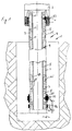
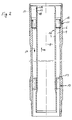
- the exemplary embodiment illustrated in the drawing of the drilling device is designed as a shaft drilling device with a drill bit 2 and a drilling drive 3.
- the drill string generally numbered 4, consists of double-walled tubes 5 which are screwed together.
- the double-wall tubes 5 have outer tubes 6 and inner tubes 7.
- the inner tube delimits an inner flow space 8.
- the outer tube 6 encasing the inner tube 7 at a distance, together with the inner tube, delimits an annular outer flow space 9.
- the inner tube 7 is supported on the outer tube by spacers 10 made of an electrically non-conductive material.
- the inner tube 7 carries a perforated centering piece 11 at its upper end in order to hold the inner tube 7 radially and axially.
- This centering piece 11 also forms a non-conductive spacer 10.
- the sleeve element which is placed on the pin of the following tube.
- a centering piece 13 is also provided, which is also made of plastic and also forms spacers 10.
- the spigot and socket part of the inner tube are arranged in relation to the outer tube 6 in such a way that the inner connection is automatically centered when the outer tubes 6 are screwed on and can therefore be introduced without additional measures.
- the sleeve and pin elements lie in a flow direction 14 of a z. B. flushing medium favorable arrangement.
- the outer tubes 6 and the inner tubes 7 made of a metallic material are, however, as mutually insulated electrical conductors for the transmission of measurement and control signals also energy, for example, formed between the surface of the earth and the bottom of the borehole during the drilling operation.
- the spacers 10 are not electrically conductive, so that the inner tubes 7 and the outer tubes 6 can transmit measurement and control signals as conductors of a two-wire system.
- a secure electrical connection is made at all connection points of inner and outer tubes 6, 7.
- the threaded connections 15 of the outer tubes 6 are provided with an electrically conductive thread grease.
- a first mold recess 16 and a second mold recess 17 are provided in the lateral surface.
- a worm spring 19 can be inserted into the mold recess 16 and, after fitting an adjacent inner tube, ensures a secure electrical connection of the interconnected inner tubes 7.
- An O-ring 18 is arranged in the mold recess for sealing.
Landscapes
- Engineering & Computer Science (AREA)
- Life Sciences & Earth Sciences (AREA)
- Geology (AREA)
- Mining & Mineral Resources (AREA)
- Mechanical Engineering (AREA)
- Physics & Mathematics (AREA)
- Environmental & Geological Engineering (AREA)
- Fluid Mechanics (AREA)
- General Life Sciences & Earth Sciences (AREA)
- Geochemistry & Mineralogy (AREA)
- Geophysics And Detection Of Objects (AREA)
- Earth Drilling (AREA)
Claims (11)
- Dispositif pour le forage en particulier d'un puits comportant un train de tiges qui comprend des tubes intérieurs (7) délimitant un espace de circulation intérieur (8) ainsi que des tubes extérieurs (6) entourant les tubes intérieurs, à distance de ceux-ci, de manière à former un espace de circulation extérieur (9), un mécanisme d'entraînement de forage (3) ainsi qu'un outil de forage (2) pouvant être entraîné par l'intermédiaire du train de tiges (4), caractérisé en ce que les tubes intérieurs et les tubes extérieurs (7, 6), ayant la forme de conducteurs électriques réciproquement isolés pour la transmission en particulier de signaux de mesure et de commande entre la surface du sol et le fond du puits, pendant l'opération de forage, peuvent prendre appui l'un sur l'autre, par l'intermédiaire d'organes d'écartement (10) non conducteurs de l'électricité, et peuvent être connectés respectivement à des dispositifs de mesure et de commande, les tubes extérieurs (6) du train de tiges (4), à leurs endroits de jonction (15), pouvant être fixés l' un à l'autre avec intercalation d'une matière de contact et les tubes intérieurs (7) emboîtables l'un dans l'autre pouvant être fixés l'un à l'autre avec intercalation d'éléments de contact (19) du type assurant la conduction de l'électricité.
- Dispositif suivant la revendication 1, caractérisé en ce que les organes d'écartement (10) sont faits d'une matière non conductrice de l'électricité.
- Dispositif suivant la revendication 1, caractérisé en ce que les organes d'écartement (10) sont revêtus d'une matière non conductrice de l'électricité.
- Dispositif suivant l'une quelconque des revendications 1 à 3, caractérisé en ce que les tubes intérieurs (7) et les organes d'écartement (10) sont réalisés d'une seule pièce.
- Dispositif suivant la revendication 1, caractérisé en ce que la matière de contact est une graisse pour pas de vis conductrice de l'électricité.
- Dispositif suivant l'une quelconque des revendications 1 à 5, caractérisé en ce que les tubes extérieurs (6) du train de tiges (4) peuvent être fixés l'un à l'autre, à leurs endroits de jonction (15) avec intercalation d'une matière de contact.
- Dispositif suivant l'une quelconque des revendications 1 à 6, caractérisé en ce que les tubes intérieurs et/ou les tubes extérieurs (7, 6) peuvent être connectés électriquement par une bague glissante (20, 21) pouvant être fixée sur le tube extérieur (6), avec laquelle un élément de contact (22) d'un dispositif de mesure et/ou de commande peut être amené en contact pendant le mouvement de rotation du train de tiges (4).
- Dispositif suivant l'une quelconque des revendications 1 à 7, caractérisé en ce que les tubes intérieurs et/ou les tubes extérieurs (7, 6) peuvent être connectés électriquement à une unité de transmission par induction (23) d'un dispositif de traitement de données à fonctionnement électrique.
- Dispositif suivant l'une quelconque des revendications 1 à 8, caractérisé en ce que les endroits de jonction (15, 19) conducteurs de l'électricité entre les tubes intérieurs et/ou les tubes extérieurs peuvent être protégés vers l'extérieur par un enrobage.
- Connexion électrique pour des tubes d'un train de tiges pouvant être fixés l'un à l'autre, en particulier pour les tubes intérieurs (7) d'un train de tiges (4) d'un dispositif (1) suivant la revendication 9, caractérisé en ce qu'à titre d'élément de contact, est prévu au moins un boudin de ressort (19) en -une matière conductrice de l'électricité, pouvant être introduit dans un évidement en forme de gorge circulaire (17).
- Connexion électrique pour des tubes d'un train de tiges pouvant être fixés l'un à l'autre, en particulier pour les tubes intérieurs (7) d'un train de tiges (4) d'un dispositif (1) suivant la revendication 10, caractérisé en ce qu'à titre d'élément de contact, est prévu au moins un élément à éventail en une matière conductrice de l'électricité, pouvant être introduit dans un évidement en forme de gorge circulaire (17).
Applications Claiming Priority (2)
| Application Number | Priority Date | Filing Date | Title |
|---|---|---|---|
| DE19904002795 DE4002795C1 (fr) | 1990-01-31 | 1990-01-31 | |
| DE4002795 | 1990-01-31 |
Publications (2)
| Publication Number | Publication Date |
|---|---|
| EP0440123A1 EP0440123A1 (fr) | 1991-08-07 |
| EP0440123B1 true EP0440123B1 (fr) | 1994-05-18 |
Family
ID=6399123
Family Applications (1)
| Application Number | Title | Priority Date | Filing Date |
|---|---|---|---|
| EP19910101043 Expired - Lifetime EP0440123B1 (fr) | 1990-01-31 | 1991-01-28 | Dispositif pour la transmission de signaux dans un trou de forage |
Country Status (3)
| Country | Link |
|---|---|
| EP (1) | EP0440123B1 (fr) |
| CA (1) | CA2035412A1 (fr) |
| DE (1) | DE4002795C1 (fr) |
Families Citing this family (7)
| Publication number | Priority date | Publication date | Assignee | Title |
|---|---|---|---|---|
| US6581454B1 (en) * | 1999-08-03 | 2003-06-24 | Shell Oil Company | Apparatus for measurement |
| DE102010018383A1 (de) * | 2010-04-26 | 2011-10-27 | Ee Technologie Gmbh | Bohr- oder Förderrohrgestänge |
| CN101824983A (zh) * | 2010-05-06 | 2010-09-08 | 煤炭科学研究总院西安研究院 | 一种信号传输装置 |
| WO2014046674A1 (fr) * | 2012-09-21 | 2014-03-27 | Halliburton Energy Services, Inc. | Système de télémétrie câblé à double enveloppe |
| CN108442887B (zh) * | 2018-03-22 | 2019-10-25 | 西南石油大学 | 一种可补偿自清洁式动力电钻杆 |
| CN113027356A (zh) * | 2021-03-30 | 2021-06-25 | 中原工学院 | 一种井下开采随钻测量无线传输钻杆及其应用 |
| CN117005856A (zh) * | 2023-08-17 | 2023-11-07 | 上海久卓机电设备有限公司 | 一种满足多介质高压输送及电信号传送的连续回转装置 |
Family Cites Families (7)
| Publication number | Priority date | Publication date | Assignee | Title |
|---|---|---|---|---|
| US2395861A (en) * | 1941-06-12 | 1946-03-05 | Cyrus H Fraser | Transmission line joint |
| EP0063444B1 (fr) * | 1981-04-10 | 1986-07-09 | Framo Developments (U.K.) Limited | Système de pompe submersible à entraînement électrique |
| JPS5864715A (ja) * | 1981-10-12 | 1983-04-18 | 三菱電機株式会社 | 炭化水素地下資源電気加熱用電極装置の電気絶縁被覆された導管の製造法 |
| US4683944A (en) * | 1985-05-06 | 1987-08-04 | Innotech Energy Corporation | Drill pipes and casings utilizing multi-conduit tubulars |
| US4643843A (en) * | 1985-06-03 | 1987-02-17 | Lowdon Harold L | Preparation for improving the reliability of electrical connections |
| GB8616006D0 (en) * | 1986-07-01 | 1986-08-06 | Framo Dev Ltd | Drilling system |
| GB8714754D0 (en) * | 1987-06-24 | 1987-07-29 | Framo Dev Ltd | Electrical conductor arrangements |
-
1990
- 1990-01-31 DE DE19904002795 patent/DE4002795C1/de not_active Expired - Lifetime
-
1991
- 1991-01-28 EP EP19910101043 patent/EP0440123B1/fr not_active Expired - Lifetime
- 1991-01-31 CA CA 2035412 patent/CA2035412A1/fr not_active Abandoned
Also Published As
| Publication number | Publication date |
|---|---|
| EP0440123A1 (fr) | 1991-08-07 |
| DE4002795C1 (fr) | 1991-05-23 |
| CA2035412A1 (fr) | 1991-08-01 |
Similar Documents
| Publication | Publication Date | Title |
|---|---|---|
| DE3852151T2 (de) | Elektrische Leitungseinrichtung für Rohrsysteme. | |
| DE3750972T2 (de) | Bohreinrichtung. | |
| DE69319239T2 (de) | Elektrische Verbindung | |
| EP0909876B1 (fr) | Système de transmission de données ou de courant électrique pour un appareil de forage | |
| DE3786398T2 (de) | Bohr- und Futterrohre mit einer Vielzahl von Leitungen. | |
| EP0426820B1 (fr) | Procede et dispositif pour transmettre des signaux de donnees et/ou de commande dans un tubage | |
| DE69434746T2 (de) | Verbesserte, mit Fett geschmierte Kabelanordnung zur Echtzeit-Oberflächenabbildung | |
| DE3035905C2 (de) | Vorrichtung zur Fernübertragung von Informationen aus einem Bohrloch zur Erdoberfläche während des Betriebs eines Bohrgeräts | |
| DE69600520T2 (de) | System zur elektrizitätsübertragung im bohrloch | |
| DE3854227T2 (de) | Verfahren und Einrichtung zur Fernbedienung einer Ausrüstung. | |
| DE60120450T2 (de) | System, verfahren und vorrichtung zum einsatz eines datenbetriebsmittels in einer gewinderohrkupplung | |
| EP0397876A1 (fr) | Procede et dispositif pour fabriquer des tubes profiles utilises pour la construction de puits | |
| DE69530666T2 (de) | Schutzschild für eine Antenne, Verschleissband und Stabilisator für ein Werkzeug zum Messen während des Bohrens | |
| DE69001031T2 (de) | Verklammernde verbindung fuer aufwickelbare roehren. | |
| DE69212581T2 (de) | Verfahren und Einrichtung zur elektrischen Verbindung von Geräten wie Bohrlochsonden | |
| DE2827295A1 (de) | Anordnung fuer bohrgestaenge mit einem anschlusstueck, einer mitnehmerstange und ggf. einem schieberteil zum verbinden mit einer fernanzeigeeinrichtung | |
| EP0440123B1 (fr) | Dispositif pour la transmission de signaux dans un trou de forage | |
| DE102004003479B4 (de) | Bohrgestänge für Tiefbohrungen | |
| DE3113749C2 (de) | Vorrichtung zur Fernübertragung von Informationen aus einem Bohrloch zur Erdoberfläche während des Betriebs eines Bohrgerätes | |
| DE3011922C2 (de) | Vorrichtung zur Markierung einer Stelle auf einer Bohrlochverrohrung | |
| DE3402386A1 (de) | Induktive energie- und datenuebertragung | |
| DE112015006745T5 (de) | Elektrische Isolierung zum Reduzieren von Magnetometerstörbeeinflussung | |
| EP3828375B1 (fr) | Enrouleur de câble pour insérer un câble de données dans une corde de forage, en particulier un perçage horizontal | |
| DE2545692B2 (de) | Einrichtung zur Übertragung von Meßdaten aus einem Bohrloch, insbesondere Tiefbohrloch | |
| EP3696369B1 (fr) | Dispositif de forage du sol pour un forage dirigé par câble, procédé de forage du sol dirigé par câble et utilisation lors du forage du sol dirigé par câble |
Legal Events
| Date | Code | Title | Description |
|---|---|---|---|
| PUAI | Public reference made under article 153(3) epc to a published international application that has entered the european phase |
Free format text: ORIGINAL CODE: 0009012 |
|
| AK | Designated contracting states |
Kind code of ref document: A1 Designated state(s): BE FR GB NL |
|
| 17P | Request for examination filed |
Effective date: 19911026 |
|
| 17Q | First examination report despatched |
Effective date: 19921204 |
|
| GRAA | (expected) grant |
Free format text: ORIGINAL CODE: 0009210 |
|
| AK | Designated contracting states |
Kind code of ref document: B1 Designated state(s): BE FR GB NL |
|
| ET | Fr: translation filed | ||
| GBT | Gb: translation of ep patent filed (gb section 77(6)(a)/1977) |
Effective date: 19940722 |
|
| PG25 | Lapsed in a contracting state [announced via postgrant information from national office to epo] |
Ref country code: GB Effective date: 19950128 |
|
| PG25 | Lapsed in a contracting state [announced via postgrant information from national office to epo] |
Ref country code: BE Effective date: 19950131 |
|
| PLBE | No opposition filed within time limit |
Free format text: ORIGINAL CODE: 0009261 |
|
| STAA | Information on the status of an ep patent application or granted ep patent |
Free format text: STATUS: NO OPPOSITION FILED WITHIN TIME LIMIT |
|
| 26N | No opposition filed | ||
| BERE | Be: lapsed |
Owner name: BAKER-HUGHES INC. Effective date: 19950131 |
|
| PG25 | Lapsed in a contracting state [announced via postgrant information from national office to epo] |
Ref country code: NL Effective date: 19950801 |
|
| GBPC | Gb: european patent ceased through non-payment of renewal fee |
Effective date: 19950128 |
|
| PG25 | Lapsed in a contracting state [announced via postgrant information from national office to epo] |
Ref country code: FR Effective date: 19950929 |
|
| NLV4 | Nl: lapsed or anulled due to non-payment of the annual fee |
Effective date: 19950801 |
|
| REG | Reference to a national code |
Ref country code: FR Ref legal event code: ST |