EP0440009B1 - Dispositif et procédé pour le refroidissement modulé d'un élément cylindrique en défilement - Google Patents
Dispositif et procédé pour le refroidissement modulé d'un élément cylindrique en défilement Download PDFInfo
- Publication number
- EP0440009B1 EP0440009B1 EP90870241A EP90870241A EP0440009B1 EP 0440009 B1 EP0440009 B1 EP 0440009B1 EP 90870241 A EP90870241 A EP 90870241A EP 90870241 A EP90870241 A EP 90870241A EP 0440009 B1 EP0440009 B1 EP 0440009B1
- Authority
- EP
- European Patent Office
- Prior art keywords
- cylindrical element
- compartments
- cooling
- orifices
- annular chamber
- Prior art date
- Legal status (The legal status is an assumption and is not a legal conclusion. Google has not performed a legal analysis and makes no representation as to the accuracy of the status listed.)
- Expired - Lifetime
Links
- 238000001816 cooling Methods 0.000 title claims description 33
- 238000000034 method Methods 0.000 title claims description 4
- 238000005192 partition Methods 0.000 claims abstract description 20
- 239000002826 coolant Substances 0.000 claims abstract description 14
- 238000009826 distribution Methods 0.000 claims description 24
- 238000000926 separation method Methods 0.000 abstract 3
- 238000005096 rolling process Methods 0.000 description 15
- 229910000831 Steel Inorganic materials 0.000 description 4
- 239000010959 steel Substances 0.000 description 4
- 238000003303 reheating Methods 0.000 description 3
- XLYOFNOQVPJJNP-UHFFFAOYSA-N water Substances O XLYOFNOQVPJJNP-UHFFFAOYSA-N 0.000 description 3
- 230000033228 biological regulation Effects 0.000 description 2
- 239000000110 cooling liquid Substances 0.000 description 2
- 239000000498 cooling water Substances 0.000 description 2
- 230000006698 induction Effects 0.000 description 2
- 230000001788 irregular Effects 0.000 description 2
- VNWKTOKETHGBQD-UHFFFAOYSA-N methane Chemical compound C VNWKTOKETHGBQD-UHFFFAOYSA-N 0.000 description 2
- 230000001105 regulatory effect Effects 0.000 description 2
- 239000007787 solid Substances 0.000 description 2
- 241000782128 Albizia adianthifolia Species 0.000 description 1
- 230000004323 axial length Effects 0.000 description 1
- 238000005452 bending Methods 0.000 description 1
- 238000005553 drilling Methods 0.000 description 1
- 230000000694 effects Effects 0.000 description 1
- 238000010438 heat treatment Methods 0.000 description 1
- 239000007788 liquid Substances 0.000 description 1
- 239000002184 metal Substances 0.000 description 1
- 230000004048 modification Effects 0.000 description 1
- 238000012986 modification Methods 0.000 description 1
- 239000003345 natural gas Substances 0.000 description 1
- 238000009828 non-uniform distribution Methods 0.000 description 1
- 230000008569 process Effects 0.000 description 1
- 230000009467 reduction Effects 0.000 description 1
- 230000009466 transformation Effects 0.000 description 1
- 238000000844 transformation Methods 0.000 description 1
- 238000003466 welding Methods 0.000 description 1
Images

Classifications
-
- C—CHEMISTRY; METALLURGY
- C21—METALLURGY OF IRON
- C21D—MODIFYING THE PHYSICAL STRUCTURE OF FERROUS METALS; GENERAL DEVICES FOR HEAT TREATMENT OF FERROUS OR NON-FERROUS METALS OR ALLOYS; MAKING METAL MALLEABLE, e.g. BY DECARBURISATION OR TEMPERING
- C21D11/00—Process control or regulation for heat treatments
- C21D11/005—Process control or regulation for heat treatments for cooling
-
- B—PERFORMING OPERATIONS; TRANSPORTING
- B21—MECHANICAL METAL-WORKING WITHOUT ESSENTIALLY REMOVING MATERIAL; PUNCHING METAL
- B21B—ROLLING OF METAL
- B21B37/00—Control devices or methods specially adapted for metal-rolling mills or the work produced thereby
- B21B37/74—Temperature control, e.g. by cooling or heating the rolls or the product
-
- B—PERFORMING OPERATIONS; TRANSPORTING
- B21—MECHANICAL METAL-WORKING WITHOUT ESSENTIALLY REMOVING MATERIAL; PUNCHING METAL
- B21B—ROLLING OF METAL
- B21B45/00—Devices for surface or other treatment of work, specially combined with or arranged in, or specially adapted for use in connection with, metal-rolling mills
- B21B45/02—Devices for surface or other treatment of work, specially combined with or arranged in, or specially adapted for use in connection with, metal-rolling mills for lubricating, cooling, or cleaning
- B21B45/0203—Cooling
- B21B45/0209—Cooling devices, e.g. using gaseous coolants
- B21B45/0215—Cooling devices, e.g. using gaseous coolants using liquid coolants, e.g. for sections, for tubes
- B21B45/0224—Cooling devices, e.g. using gaseous coolants using liquid coolants, e.g. for sections, for tubes for wire, rods, rounds, bars
-
- B—PERFORMING OPERATIONS; TRANSPORTING
- B21—MECHANICAL METAL-WORKING WITHOUT ESSENTIALLY REMOVING MATERIAL; PUNCHING METAL
- B21B—ROLLING OF METAL
- B21B17/00—Tube-rolling by rollers of which the axes are arranged essentially perpendicular to the axis of the work, e.g. "axial" tube-rolling
- B21B17/14—Tube-rolling by rollers of which the axes are arranged essentially perpendicular to the axis of the work, e.g. "axial" tube-rolling without mandrel, e.g. stretch-reducing mills
Definitions
- Such a non-uniform distribution of the surface temperature is observed in particular in the tubes leaving horizontally from the reducing rolling mill, without rotation about their longitudinal axis.
- These tubes may have, between their upper generator and their lower generator, a significant difference in temperature, which may for example be of the order of 50 ° C. This difference does not result from an abrupt variation, but rather from a continuous variation of the temperature between these two generators.
- the origin of this temperature variation can be multiple.
- the cylindrical element hollow or solid, is subjected to differential cooling, during its reduction rolling, caused by the coolant of the rolls of the rolling mill.
- the upper part of the cylindrical element tends to be cooler than its lower part.
- the thermal state of the cylindrical element is particularly disturbed in the case of welded tubes, mentioned above, because the two aforementioned effects can accumulate there in extremely variable proportions.
- the device known from the aforementioned document BE-A-1002565 ensures homogeneous cooling, which hardly remedies this lack of uniformity in the surface temperature. It follows that the allotropic transformations do not occur at the same time throughout the surface area of a section of the cylindrical element, and that the latter is the seat of undesirable deformations during its cooling.
- the object of the present invention is to remedy this significant drawback, by proposing on the one hand a device making it possible to modulate the cooling of a cylindrical element, and on the other hand a method for regulating this modulated cooling.
- a device for the modulated cooling of a scrolling cylindrical element which comprises a tubular conduit pierced with a plurality of orifices, through which passes said cylindrical element to be cooled, and an envelope disposed around said tubular conduit to form therewith an annular chamber surrounding said cylindrical element to be cooled, said annular chamber being closed at its ends by walls, is characterized in that the internal volume of said annular chamber is divided into at least two compartments which do not communicate with each other, in that said division into compartments is carried out by at least two partition walls fixed on the one hand to the outer surface of said tubular conduit and on the other hand to the inner surface of at least one wall delimiting said annular chamber, in that said partitions divide said plurality of orifices into at least two groups of orifices, each of said compartments comprising one of said groups of orifices, and in that each of said compartments is equipped with means for supplying coolant.
- the envelope disposed around the aforementioned tubular conduit can in principle have any shape. It is however preferable that it is cylindrical, and that it is also coaxial with said tubular conduit. It thus forms with this tubular conduit an annular chamber of constant radial height which promotes a regular flow of the cooling agent.
- At least one of said partition walls is arranged helically on the outer surface of said tubular conduit.
- said means for supplying at least one of said compartments comprise means for adjusting the flow rate of the cooling agent.
- the cross section of the tube is assimilated to a clock face, so that the upper and lower generators are respectively in the positions corresponding to 12 o'clock and 6 o'clock.
- the tube As indicated above, part of the cooling water used during the forming of the tube is trapped inside of it. This water vaporizes during the subsequent reheating, which compromises the uniformity of the temperature of the tube before it enters the reducing rolling mill. In the latter, the tube still undergoes irregular cooling due to the cooling water of the cylinders. As a result, at the outlet of the reducing rolling mill, the tube has a temperature distribution which is not uniform.
- Figure 1 shows an example of such a temperature distribution along the perimeter of a cross section of the tube; for simplicity, a symmetrical distribution has been chosen with respect to the vertical plane of symmetry of the tube.
- the tube is considered to be split along its upper generatrix (12 h) and the perimeter of the section has been developed along the horizontal axis.
- Curve (a) represents the distribution of the temperature Te of the surface of the tube along the perimeter of a section of the tube at the outlet of the reducing rolling mill, that is to say at the inlet of the cooling device.
- the cooling applied to the tube in the device of the invention aims to standardize the distribution of the surface temperature of the tube at the outlet of this device.
- Curve (a) shows that this cooling must be modulated, that is to say must be more vigorous in the upper part of the tube (12 h) than in its lower part (6 h).
- Curve (b) indicates a typical distribution of the flow rate Q of the coolant along the perimeter of the section of the tube, to ensure the desired modulated cooling.
- This cooling can be adjusted so that the tube leaving the cooling device has a uniform temperature distribution Ts, illustrated here by the horizontal line (c).
- Figure 2 shows a tubular conduit of a device according to the invention, capable of providing modulated cooling of the type illustrated in Figure 1.
- the direction of travel of the product is indicated by a arrow.
- a tubular conduit 1 provided with two partition walls 2,3 fixed on the external surface of the conduit 1.
- the conduit 1 was split along its upper generatrix (12 h) and we developed it to represent it in plan.
- the face visible in Figure 2 is the interior surface of the tubular conduit, and the dashed lines 2, 3 indicate the position of the partitions 2, 3 fixed on the exterior surface of the conduit, as explained above.
- the tubular conduit 1 is pierced with a plurality of orifices, which are divided into two groups according to their position relative to the partition walls 2,3.
- the position of the coolant supply orifices in the compartments created in the annular chamber by the partition walls has also been shown diagrammatically; these upper and lower supply orifices, respectively As and Ai, are in fact provided in the envelope surrounding the tubular conduit 1, which is not shown here.
- the two partition walls 2,3 are arranged so as to form, in the direction of travel of the cylindrical element to be cooled, an upper compartment Cs diverging and a lower compartment Ci converge.
- the partition walls 2,3 appear rectilinear; however, they take on a helical shape when the duct is returned to its tubular shape.
- the flow rate of the coolant in each compartment can be adjusted by any appropriate means, for example by varying the actual feed rate of this liquid, and / or by modifying the number of passage orifices located in these compartments.
- the passage orifices can be distributed in any manner known per se in the tubular conduit 1, for example in staggered rows, along helical lines or in flat crowns. They can also, individually or in any number, be provided with closing means making it possible to contribute to the modulation of the flow rate of the cooling liquid.
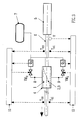
- the modulation of the cooling of a cylindrical element by means of a device comprising such an annular chamber with compartments can be controlled automatically, for example by means of the regulation system illustrated in FIG. 3.
- the cooling device according to the invention is installed at the outlet of a hot reducing rolling mill, in which the steel tube has been brought to its final outside diameter.
- Figure 3 schematically shows the cooling device 4, with the tubular conduit 1 and the partition walls 2,3 indicated by broken lines, the reducing rolling mill 5 and the steel tube 6 to be cooled.
- the tube 6 moves from right to left, as indicated by the arrow.
- the cooling device 4 is supplied with cooling liquid from a source 7, via lines 8 and 9.
- the tube 6 emerging from the reducing rolling mill 5 has a temperature distribution of the type of curve (a) in FIG. 1, possibly with irregular fluctuations over time.
- the objective is to achieve a temperature distribution of type (c), as uniform and as stable as possible, at the outlet of the cooling device 4.
- the speed V of the tube 6 at the outlet of the reducing rolling mill 5 is measured, which is in fact the speed with which the tube 6 passes through the cooling device 4.
- the surface temperature of the tube 6 is also measured at l input of the device 4, in particular to its upper generator (Tes) and to its lower generator (Tei). These values make it possible to determine the distribution of the temperature on the surface of the tube, i.e. the cylindrical element to be cooled, at the inlet of the cooling device.
- the surface temperature of the tube 6 at the outlet of the device 4 is also measured, in particular at the upper generator (Tss) and at the lower generator (Tsi). This determines the temperature distribution on the surface of the tube, that is to say of the cylindrical element, at the outlet of the cooling device.
- This output distribution is compared with a desired temperature distribution and at least one of the flow rates Qs, Qi is varied to cancel the differences observed between these two temperature distributions.
- the regulation of the cooling process is preferably placed under the control of a processor 10.
- the processor 10 is represented in two parts, for the simple purpose of preserving the clarity of the drawing.
Landscapes
- Engineering & Computer Science (AREA)
- Mechanical Engineering (AREA)
- Chemical & Material Sciences (AREA)
- Physics & Mathematics (AREA)
- Thermal Sciences (AREA)
- Crystallography & Structural Chemistry (AREA)
- Materials Engineering (AREA)
- Metallurgy (AREA)
- Organic Chemistry (AREA)
- Metal Rolling (AREA)
- Heat Treatment Of Articles (AREA)
- Extrusion Moulding Of Plastics Or The Like (AREA)
Priority Applications (1)
| Application Number | Priority Date | Filing Date | Title |
|---|---|---|---|
| AT90870241T ATE95089T1 (de) | 1990-02-01 | 1990-12-18 | Vorrichtung und verfahren zur modulierten kuehlung eines sich bewegenden zylindrischen gegenstandes. |
Applications Claiming Priority (2)
| Application Number | Priority Date | Filing Date | Title |
|---|---|---|---|
| BE9000122 | 1990-02-01 | ||
| BE9000122A BE1003665A6 (fr) | 1990-02-01 | 1990-02-01 | Dispositif et procede pour le refroidissement module d'un element cylindrique en defilement. |
Publications (3)
| Publication Number | Publication Date |
|---|---|
| EP0440009A2 EP0440009A2 (fr) | 1991-08-07 |
| EP0440009A3 EP0440009A3 (en) | 1991-12-27 |
| EP0440009B1 true EP0440009B1 (fr) | 1993-09-29 |
Family
ID=3884660
Family Applications (1)
| Application Number | Title | Priority Date | Filing Date |
|---|---|---|---|
| EP90870241A Expired - Lifetime EP0440009B1 (fr) | 1990-02-01 | 1990-12-18 | Dispositif et procédé pour le refroidissement modulé d'un élément cylindrique en défilement |
Country Status (5)
| Country | Link |
|---|---|
| EP (1) | EP0440009B1 (ja) |
| JP (1) | JPH04220111A (ja) |
| AT (1) | ATE95089T1 (ja) |
| BE (1) | BE1003665A6 (ja) |
| DE (1) | DE69003667D1 (ja) |
Families Citing this family (1)
| Publication number | Priority date | Publication date | Assignee | Title |
|---|---|---|---|---|
| EP2792428A1 (de) * | 2013-04-15 | 2014-10-22 | Siemens VAI Metals Technologies GmbH | Kühleinrichtung mit breitenabhängiger Kühlwirkung |
Family Cites Families (6)
| Publication number | Priority date | Publication date | Assignee | Title |
|---|---|---|---|---|
| LU79722A1 (fr) * | 1978-05-26 | 1979-06-13 | Arbed | Perfectionnements aux dispositifs de refroidissement de produits lamines metalliques |
| JPS58136275U (ja) * | 1982-03-04 | 1983-09-13 | エヌエス工業株式会社 | ホ−ス接続金具の締付装置 |
| DE3424550A1 (de) * | 1984-07-04 | 1986-01-16 | Fried. Krupp Gmbh, 4300 Essen | Kuehlmittel-zufuehreinrichtung |
| BE904177A (fr) * | 1986-02-05 | 1986-08-05 | Centre Rech Metallurgique | Dispositif de refroidissement d'un produit metallique en mouvement. |
| JPH0253326U (ja) * | 1988-10-12 | 1990-04-17 | ||
| BE1002565A6 (fr) * | 1988-10-24 | 1991-03-26 | Centre Rech Metallurgique | Dispositif de refroidissement d'un element cylindrique en defilement. |
-
1990
- 1990-02-01 BE BE9000122A patent/BE1003665A6/fr not_active IP Right Cessation
- 1990-12-18 EP EP90870241A patent/EP0440009B1/fr not_active Expired - Lifetime
- 1990-12-18 AT AT90870241T patent/ATE95089T1/de active
- 1990-12-18 DE DE90870241T patent/DE69003667D1/de not_active Expired - Lifetime
-
1991
- 1991-02-01 JP JP3012034A patent/JPH04220111A/ja active Pending
Also Published As
| Publication number | Publication date |
|---|---|
| ATE95089T1 (de) | 1993-10-15 |
| DE69003667D1 (de) | 1993-11-04 |
| JPH04220111A (ja) | 1992-08-11 |
| EP0440009A3 (en) | 1991-12-27 |
| EP0440009A2 (fr) | 1991-08-07 |
| BE1003665A6 (fr) | 1992-05-19 |
Similar Documents
| Publication | Publication Date | Title |
|---|---|---|
| FR2477597A1 (fr) | Structure de rouleau pour machine a papier et son procede de chauffage | |
| EP1268158B1 (fr) | Procede et ligne de fabrication en continu de tubes en matiere plastique avec etirage bi-axial | |
| EP0126111B1 (fr) | Procede et dispositif de traitement thermique de fluide comportant une condensation rapide de vapeur | |
| FR2746599A1 (fr) | Appareil et procede de traitement de produits utilisant un milieu de traitement gazeux et convoyeur pour un dispositif de traitement d'aliments | |
| FR2470354A1 (fr) | Echangeur de chaleur comprenant des tubes disposes en un groupe d'anneaux concentriques | |
| FR2529476A1 (fr) | Cellule de flottation | |
| BE486783A (fr) | Procédé de fabrication de produits tubulaires à parois minces et appareillage en permettant la mise en oeuvre | |
| CH643481A5 (fr) | Dispositif pour le calibrage d'un tube en matiere plastique produit par extrusion. | |
| EP0795389A1 (fr) | Procédé et dispositif pour le refroidissement interne de tuyaux en matière plastique | |
| EP0440009B1 (fr) | Dispositif et procédé pour le refroidissement modulé d'un élément cylindrique en défilement | |
| FR2530531A1 (fr) | Procede et appareil pour refroidir interieurement des objets tubulaires au cours de leur extrusion | |
| EP0014140B1 (fr) | Dispositif pour refroidir un produit long en défilement | |
| EP0274317B1 (fr) | Procédé et installation d'extrusion d'un produit en forme de film, de plaque, de tube, de tige ou de fil | |
| FR2733039A1 (fr) | Echangeur de chaleur a plaques brassees, et procede correspondant de traitement d'un fluide diphasique | |
| EP2271221A2 (fr) | Dispositif de debacterisation thermique en continu de produits sous forme de solides divises | |
| FR2479037A1 (fr) | Laminoir oblique pour la fabrication de tubes sans soudure | |
| EP2883013A2 (fr) | Absorbeur a echangeur a plaque spiralee avec alimentation fluidique homogene | |
| FR2479291A1 (fr) | Appareil pour le traitement de matieres, telles que des textiles, a l'aide d'un liquide de traitement | |
| FR2494626A1 (fr) | Procede et appareil de fabrication d'elements de turbulence en resine synthetique | |
| FR2685458A1 (fr) | Tambour pour le refroidissement de produits en feuille ou plaque. | |
| FR2744200A1 (fr) | Boite de chauffe comportant des tubes a infra-rouges pour le chauffage d'une feuille de matiere plastique avant son formage et procede de chauffage mis en oeuvre avec une telle boite de chauffe | |
| WO2023247881A1 (fr) | Dispositif de refroidissement par fluide d'une surface chaude et plaque de presse ou moule associe | |
| EP0328505B1 (fr) | Installation de refroidissement d'une barre ou d'un fil métallique | |
| FR2806957A1 (fr) | Procede et ligne pour fabriquer en continu des tubes en matiere plastique avec etirage bi-axial, et tube en matiere plastique obtenu | |
| BE832391R (fr) | Procede et dispositif de patentage de fils d'acier |
Legal Events
| Date | Code | Title | Description |
|---|---|---|---|
| PUAI | Public reference made under article 153(3) epc to a published international application that has entered the european phase |
Free format text: ORIGINAL CODE: 0009012 |
|
| AK | Designated contracting states |
Kind code of ref document: A2 Designated state(s): AT BE DE ES FR GB IT LU NL SE |
|
| PUAL | Search report despatched |
Free format text: ORIGINAL CODE: 0009013 |
|
| AK | Designated contracting states |
Kind code of ref document: A3 Designated state(s): AT BE DE ES FR GB IT LU NL SE |
|
| 17P | Request for examination filed |
Effective date: 19920610 |
|
| 17Q | First examination report despatched |
Effective date: 19921214 |
|
| GRAA | (expected) grant |
Free format text: ORIGINAL CODE: 0009210 |
|
| AK | Designated contracting states |
Kind code of ref document: B1 Designated state(s): AT BE DE ES FR GB IT LU NL SE |
|
| PG25 | Lapsed in a contracting state [announced via postgrant information from national office to epo] |
Ref country code: IT Free format text: LAPSE BECAUSE OF FAILURE TO SUBMIT A TRANSLATION OF THE DESCRIPTION OR TO PAY THE FEE WITHIN THE PRE;WARNING: LAPSES OF ITALIAN PATENTS WITH EFFECTIVE DATE BEFORE 2007 MAY HAVE OCCURRED AT ANY TIME BEFORE 2007. THE CORRECT EFFECTIVE DATE MAY BE DIFFERENT FROM THE ONE RECORDED.SCRIBED TIME-LIMIT Effective date: 19930929 Ref country code: GB Effective date: 19930929 Ref country code: SE Effective date: 19930929 Ref country code: NL Effective date: 19930929 Ref country code: ES Free format text: THE PATENT HAS BEEN ANNULLED BY A DECISION OF A NATIONAL AUTHORITY Effective date: 19930929 Ref country code: DE Effective date: 19930929 Ref country code: AT Effective date: 19930929 |
|
| REF | Corresponds to: |
Ref document number: 95089 Country of ref document: AT Date of ref document: 19931015 Kind code of ref document: T |
|
| REF | Corresponds to: |
Ref document number: 69003667 Country of ref document: DE Date of ref document: 19931104 |
|
| PG25 | Lapsed in a contracting state [announced via postgrant information from national office to epo] |
Ref country code: LU Free format text: LAPSE BECAUSE OF NON-PAYMENT OF DUE FEES Effective date: 19931231 Ref country code: BE Effective date: 19931231 |
|
| NLV1 | Nl: lapsed or annulled due to failure to fulfill the requirements of art. 29p and 29m of the patents act | ||
| GBV | Gb: ep patent (uk) treated as always having been void in accordance with gb section 77(7)/1977 [no translation filed] |
Effective date: 19930929 |
|
| BERE | Be: lapsed |
Owner name: CENTRE DE RECHERCHES METALLURGIQUES CENTRUM VOOR Effective date: 19931231 |
|
| PLBE | No opposition filed within time limit |
Free format text: ORIGINAL CODE: 0009261 |
|
| STAA | Information on the status of an ep patent application or granted ep patent |
Free format text: STATUS: NO OPPOSITION FILED WITHIN TIME LIMIT |
|
| PG25 | Lapsed in a contracting state [announced via postgrant information from national office to epo] |
Ref country code: FR Effective date: 19940831 |
|
| 26N | No opposition filed | ||
| REG | Reference to a national code |
Ref country code: FR Ref legal event code: ST |