EP0440009B1 - Device and method for the modulated cooling of a moving cylindrical object - Google Patents
Device and method for the modulated cooling of a moving cylindrical object Download PDFInfo
- Publication number
- EP0440009B1 EP0440009B1 EP90870241A EP90870241A EP0440009B1 EP 0440009 B1 EP0440009 B1 EP 0440009B1 EP 90870241 A EP90870241 A EP 90870241A EP 90870241 A EP90870241 A EP 90870241A EP 0440009 B1 EP0440009 B1 EP 0440009B1
- Authority
- EP
- European Patent Office
- Prior art keywords
- cylindrical element
- compartments
- cooling
- orifices
- annular chamber
- Prior art date
- Legal status (The legal status is an assumption and is not a legal conclusion. Google has not performed a legal analysis and makes no representation as to the accuracy of the status listed.)
- Expired - Lifetime
Links
Images

Classifications
-
- C—CHEMISTRY; METALLURGY
- C21—METALLURGY OF IRON
- C21D—MODIFYING THE PHYSICAL STRUCTURE OF FERROUS METALS; GENERAL DEVICES FOR HEAT TREATMENT OF FERROUS OR NON-FERROUS METALS OR ALLOYS; MAKING METAL MALLEABLE, e.g. BY DECARBURISATION OR TEMPERING
- C21D11/00—Process control or regulation for heat treatments
- C21D11/005—Process control or regulation for heat treatments for cooling
-
- B—PERFORMING OPERATIONS; TRANSPORTING
- B21—MECHANICAL METAL-WORKING WITHOUT ESSENTIALLY REMOVING MATERIAL; PUNCHING METAL
- B21B—ROLLING OF METAL
- B21B37/00—Control devices or methods specially adapted for metal-rolling mills or the work produced thereby
- B21B37/74—Temperature control, e.g. by cooling or heating the rolls or the product
-
- B—PERFORMING OPERATIONS; TRANSPORTING
- B21—MECHANICAL METAL-WORKING WITHOUT ESSENTIALLY REMOVING MATERIAL; PUNCHING METAL
- B21B—ROLLING OF METAL
- B21B45/00—Devices for surface or other treatment of work, specially combined with or arranged in, or specially adapted for use in connection with, metal-rolling mills
- B21B45/02—Devices for surface or other treatment of work, specially combined with or arranged in, or specially adapted for use in connection with, metal-rolling mills for lubricating, cooling, or cleaning
- B21B45/0203—Cooling
- B21B45/0209—Cooling devices, e.g. using gaseous coolants
- B21B45/0215—Cooling devices, e.g. using gaseous coolants using liquid coolants, e.g. for sections, for tubes
- B21B45/0224—Cooling devices, e.g. using gaseous coolants using liquid coolants, e.g. for sections, for tubes for wire, rods, rounds, bars
-
- B—PERFORMING OPERATIONS; TRANSPORTING
- B21—MECHANICAL METAL-WORKING WITHOUT ESSENTIALLY REMOVING MATERIAL; PUNCHING METAL
- B21B—ROLLING OF METAL
- B21B17/00—Tube-rolling by rollers of which the axes are arranged essentially perpendicular to the axis of the work, e.g. "axial" tube-rolling
- B21B17/14—Tube-rolling by rollers of which the axes are arranged essentially perpendicular to the axis of the work, e.g. "axial" tube-rolling without mandrel, e.g. stretch-reducing mills
Definitions
- Such a non-uniform distribution of the surface temperature is observed in particular in the tubes leaving horizontally from the reducing rolling mill, without rotation about their longitudinal axis.
- These tubes may have, between their upper generator and their lower generator, a significant difference in temperature, which may for example be of the order of 50 ° C. This difference does not result from an abrupt variation, but rather from a continuous variation of the temperature between these two generators.
- the origin of this temperature variation can be multiple.
- the cylindrical element hollow or solid, is subjected to differential cooling, during its reduction rolling, caused by the coolant of the rolls of the rolling mill.
- the upper part of the cylindrical element tends to be cooler than its lower part.
- the thermal state of the cylindrical element is particularly disturbed in the case of welded tubes, mentioned above, because the two aforementioned effects can accumulate there in extremely variable proportions.
- the device known from the aforementioned document BE-A-1002565 ensures homogeneous cooling, which hardly remedies this lack of uniformity in the surface temperature. It follows that the allotropic transformations do not occur at the same time throughout the surface area of a section of the cylindrical element, and that the latter is the seat of undesirable deformations during its cooling.
- the object of the present invention is to remedy this significant drawback, by proposing on the one hand a device making it possible to modulate the cooling of a cylindrical element, and on the other hand a method for regulating this modulated cooling.
- a device for the modulated cooling of a scrolling cylindrical element which comprises a tubular conduit pierced with a plurality of orifices, through which passes said cylindrical element to be cooled, and an envelope disposed around said tubular conduit to form therewith an annular chamber surrounding said cylindrical element to be cooled, said annular chamber being closed at its ends by walls, is characterized in that the internal volume of said annular chamber is divided into at least two compartments which do not communicate with each other, in that said division into compartments is carried out by at least two partition walls fixed on the one hand to the outer surface of said tubular conduit and on the other hand to the inner surface of at least one wall delimiting said annular chamber, in that said partitions divide said plurality of orifices into at least two groups of orifices, each of said compartments comprising one of said groups of orifices, and in that each of said compartments is equipped with means for supplying coolant.
- the envelope disposed around the aforementioned tubular conduit can in principle have any shape. It is however preferable that it is cylindrical, and that it is also coaxial with said tubular conduit. It thus forms with this tubular conduit an annular chamber of constant radial height which promotes a regular flow of the cooling agent.
- At least one of said partition walls is arranged helically on the outer surface of said tubular conduit.
- said means for supplying at least one of said compartments comprise means for adjusting the flow rate of the cooling agent.
- the cross section of the tube is assimilated to a clock face, so that the upper and lower generators are respectively in the positions corresponding to 12 o'clock and 6 o'clock.
- the tube As indicated above, part of the cooling water used during the forming of the tube is trapped inside of it. This water vaporizes during the subsequent reheating, which compromises the uniformity of the temperature of the tube before it enters the reducing rolling mill. In the latter, the tube still undergoes irregular cooling due to the cooling water of the cylinders. As a result, at the outlet of the reducing rolling mill, the tube has a temperature distribution which is not uniform.
- Figure 1 shows an example of such a temperature distribution along the perimeter of a cross section of the tube; for simplicity, a symmetrical distribution has been chosen with respect to the vertical plane of symmetry of the tube.
- the tube is considered to be split along its upper generatrix (12 h) and the perimeter of the section has been developed along the horizontal axis.
- Curve (a) represents the distribution of the temperature Te of the surface of the tube along the perimeter of a section of the tube at the outlet of the reducing rolling mill, that is to say at the inlet of the cooling device.
- the cooling applied to the tube in the device of the invention aims to standardize the distribution of the surface temperature of the tube at the outlet of this device.
- Curve (a) shows that this cooling must be modulated, that is to say must be more vigorous in the upper part of the tube (12 h) than in its lower part (6 h).
- Curve (b) indicates a typical distribution of the flow rate Q of the coolant along the perimeter of the section of the tube, to ensure the desired modulated cooling.
- This cooling can be adjusted so that the tube leaving the cooling device has a uniform temperature distribution Ts, illustrated here by the horizontal line (c).
- Figure 2 shows a tubular conduit of a device according to the invention, capable of providing modulated cooling of the type illustrated in Figure 1.
- the direction of travel of the product is indicated by a arrow.
- a tubular conduit 1 provided with two partition walls 2,3 fixed on the external surface of the conduit 1.
- the conduit 1 was split along its upper generatrix (12 h) and we developed it to represent it in plan.
- the face visible in Figure 2 is the interior surface of the tubular conduit, and the dashed lines 2, 3 indicate the position of the partitions 2, 3 fixed on the exterior surface of the conduit, as explained above.
- the tubular conduit 1 is pierced with a plurality of orifices, which are divided into two groups according to their position relative to the partition walls 2,3.
- the position of the coolant supply orifices in the compartments created in the annular chamber by the partition walls has also been shown diagrammatically; these upper and lower supply orifices, respectively As and Ai, are in fact provided in the envelope surrounding the tubular conduit 1, which is not shown here.
- the two partition walls 2,3 are arranged so as to form, in the direction of travel of the cylindrical element to be cooled, an upper compartment Cs diverging and a lower compartment Ci converge.
- the partition walls 2,3 appear rectilinear; however, they take on a helical shape when the duct is returned to its tubular shape.
- the flow rate of the coolant in each compartment can be adjusted by any appropriate means, for example by varying the actual feed rate of this liquid, and / or by modifying the number of passage orifices located in these compartments.
- the passage orifices can be distributed in any manner known per se in the tubular conduit 1, for example in staggered rows, along helical lines or in flat crowns. They can also, individually or in any number, be provided with closing means making it possible to contribute to the modulation of the flow rate of the cooling liquid.
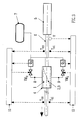
- the modulation of the cooling of a cylindrical element by means of a device comprising such an annular chamber with compartments can be controlled automatically, for example by means of the regulation system illustrated in FIG. 3.
- the cooling device according to the invention is installed at the outlet of a hot reducing rolling mill, in which the steel tube has been brought to its final outside diameter.
- Figure 3 schematically shows the cooling device 4, with the tubular conduit 1 and the partition walls 2,3 indicated by broken lines, the reducing rolling mill 5 and the steel tube 6 to be cooled.
- the tube 6 moves from right to left, as indicated by the arrow.
- the cooling device 4 is supplied with cooling liquid from a source 7, via lines 8 and 9.
- the tube 6 emerging from the reducing rolling mill 5 has a temperature distribution of the type of curve (a) in FIG. 1, possibly with irregular fluctuations over time.
- the objective is to achieve a temperature distribution of type (c), as uniform and as stable as possible, at the outlet of the cooling device 4.
- the speed V of the tube 6 at the outlet of the reducing rolling mill 5 is measured, which is in fact the speed with which the tube 6 passes through the cooling device 4.
- the surface temperature of the tube 6 is also measured at l input of the device 4, in particular to its upper generator (Tes) and to its lower generator (Tei). These values make it possible to determine the distribution of the temperature on the surface of the tube, i.e. the cylindrical element to be cooled, at the inlet of the cooling device.
- the surface temperature of the tube 6 at the outlet of the device 4 is also measured, in particular at the upper generator (Tss) and at the lower generator (Tsi). This determines the temperature distribution on the surface of the tube, that is to say of the cylindrical element, at the outlet of the cooling device.
- This output distribution is compared with a desired temperature distribution and at least one of the flow rates Qs, Qi is varied to cancel the differences observed between these two temperature distributions.
- the regulation of the cooling process is preferably placed under the control of a processor 10.
- the processor 10 is represented in two parts, for the simple purpose of preserving the clarity of the drawing.
Landscapes
- Engineering & Computer Science (AREA)
- Mechanical Engineering (AREA)
- Chemical & Material Sciences (AREA)
- Physics & Mathematics (AREA)
- Thermal Sciences (AREA)
- Crystallography & Structural Chemistry (AREA)
- Materials Engineering (AREA)
- Metallurgy (AREA)
- Organic Chemistry (AREA)
- Metal Rolling (AREA)
- Heat Treatment Of Articles (AREA)
- Extrusion Moulding Of Plastics Or The Like (AREA)
Abstract
Description
La présente invention concerne le refroidissement d'un élément cylindrique en défilement, tel qu'un tube métallique à la sortie d'un laminoir réducteur.The present invention relates to the cooling of a scrolling cylindrical element, such as a metal tube at the outlet of a reducing rolling mill.
On connaît déjà, par le document BE-A-1002565, un dispositif de refroidissement d'un élément cylindrique en défilement, qui comporte une enveloppe disposée autour d'un conduit tubulaire perforé, avec lequel elle forme une chambre annulaire entourant l'élément cylindrique à refroidir. Le conduit tubulaire présente des perforations livrant passage au liquide de refroidissement de l'élément cylindrique. Ce dispositif connu assure un refroidissement homogène de l'élément cylindrique qui le traverse.Already known from document BE-A-1002565, a device for cooling a scrolling cylindrical element, which comprises an envelope disposed around a perforated tubular conduit, with which it forms an annular chamber surrounding the cylindrical element to cool. The tubular conduit has perforations providing passage to the coolant of the cylindrical element. This known device ensures uniform cooling of the cylindrical element which passes through it.
Dans la pratique industrielle cependant, on constate fréquemment que la distribution de la température de surface n'est pas uniforme le long du périmètre d'une section de l'élément cylindrique.In industrial practice, however, it is frequently found that the distribution of the surface temperature is not uniform along the perimeter of a section of the cylindrical member.
Une telle distribution non uniforme de la température de surface s'observe notamment dans les tubes sortant horizontalement du laminoir réducteur, sans rotation autour de leur axe longitudinal. Ces tubes peuvent présenter, entre leur génératrice supérieure et leur génératrice inférieure, une différence sensible de température, qui peut par exemple être de l'ordre de 50°C. Cette différence ne résulte pas d'une variation brusque, mais bien d'une variation continue de la température entre ces deux génératrices.Such a non-uniform distribution of the surface temperature is observed in particular in the tubes leaving horizontally from the reducing rolling mill, without rotation about their longitudinal axis. These tubes may have, between their upper generator and their lower generator, a significant difference in temperature, which may for example be of the order of 50 ° C. This difference does not result from an abrupt variation, but rather from a continuous variation of the temperature between these two generators.
L'origine de cette variation de la température peut être multiple.The origin of this temperature variation can be multiple.
Dans le cas particulier des tubes soudés, il peut subsister dans le tube de l'eau résiduelle provenant de l'opération de formage du tube. Cette eau a tendance à perturber le réchauffage du tube, en particulier dans sa partie inférieure, lors du passage de ce tube dans les fours de réchauffage, par exemple au gaz naturel ou à induction, avant son entrée dans le laminoir.In the particular case of welded tubes, there may remain in the tube residual water from the tube forming operation. This water tends to disturb the heating of the tube, in particularly in its lower part, during the passage of this tube in reheating furnaces, for example with natural gas or induction, before it enters the rolling mill.
Il se produit également une distribution hétérogène de la température dans certains types de tubes sans soudure, en particulier ceux qui sont formés par perçage et étirage à partir d'une ébauche pleine préchauffée. Le formage du tube perturbe fréquemment le profil de température de celui-ci, et un réchauffage éventuel n'améliore en général pas la situation.Heterogeneous temperature distribution also occurs in some types of seamless tubes, particularly those formed by drilling and drawing from a preheated solid blank. The forming of the tube frequently disturbs the temperature profile thereof, and any reheating does not generally improve the situation.
D'autre part, l'élément cylindrique, creux ou plein, est soumis à un refroidissement différentiel, pendant son laminage de réduction, provoqué par le liquide de refroidissement des cylindres du laminoir. Il en résulte que la partie supérieure de l'élément cylindrique a tendance à être plus froide que sa partie inférieure.On the other hand, the cylindrical element, hollow or solid, is subjected to differential cooling, during its reduction rolling, caused by the coolant of the rolls of the rolling mill. As a result, the upper part of the cylindrical element tends to be cooler than its lower part.
L'état thermique de l'élément cylindrique est particulièrement perturbé dans le cas des tubes soudés, évoqué ci-dessus, car les deux effets précités peuvent s'y cumuler dans des proportions extrêmement variables.The thermal state of the cylindrical element is particularly disturbed in the case of welded tubes, mentioned above, because the two aforementioned effects can accumulate there in extremely variable proportions.
Le dispositif connu par le document BE-A-1002565 précité assure un refroidissement homogène, qui ne remédie guère à ce manque d'uniformité de la température de surface. Il en résulte que les transformations allotropiques ne se produisent pas au même moment dans toute la zone superficielle d'une section de l'élément cylindrique, et que celui-ci est le siège de déformations indésirables au cours de son refroidissement.The device known from the aforementioned document BE-A-1002565 ensures homogeneous cooling, which hardly remedies this lack of uniformity in the surface temperature. It follows that the allotropic transformations do not occur at the same time throughout the surface area of a section of the cylindrical element, and that the latter is the seat of undesirable deformations during its cooling.
La présente invention a pour objet de remédier à cet inconvénient important, en proposant d'une part un dispositif permettant de moduler le refroidissement d'un élément cylindrique, et d'autre part un procédé de régulation de ce refroidissement modulé.The object of the present invention is to remedy this significant drawback, by proposing on the one hand a device making it possible to modulate the cooling of a cylindrical element, and on the other hand a method for regulating this modulated cooling.
Conformément à la présente invention, un dispositif pour le refroidissement modulé d'un élément cylindrique en défilement, qui comporte un conduit tubulaire percé d'une pluralité d'orifices, à travers lequel défile ledit élément cylindrique à refroidir, et une enveloppe disposée autour dudit conduit tubulaire pour former avec celui-ci une chambre annulaire entourant ledit élément cylindrique à refroidir, ladite chambre annulaire étant fermée à ses extrémités par des parois, est caractérisé en ce que le volume intérieur de ladite chambre annulaire est divisé en au moins deux compartiments qui ne communiquent pas entre eux, en ce que ladite division en compartiments est réalisée par au moins deux cloisons de séparation fixées d'une part à la surface extérieure dudit conduit tubulaire et d'autre part à la surface intérieure d'au moins une paroi délimitant ladite chambre annulaire, en ce que lesdites cloisons divisent ladite pluralité d'orifices en au moins deux groupes d'orifices, chacun desdits compartiments comportant un desdits groupes d'orifices, et en ce que chacun desdits compartiments est équipé de moyens d'alimentation en agent de refroidissement.According to the present invention, a device for the modulated cooling of a scrolling cylindrical element, which comprises a tubular conduit pierced with a plurality of orifices, through which passes said cylindrical element to be cooled, and an envelope disposed around said tubular conduit to form therewith an annular chamber surrounding said cylindrical element to be cooled, said annular chamber being closed at its ends by walls, is characterized in that the internal volume of said annular chamber is divided into at least two compartments which do not communicate with each other, in that said division into compartments is carried out by at least two partition walls fixed on the one hand to the outer surface of said tubular conduit and on the other hand to the inner surface of at least one wall delimiting said annular chamber, in that said partitions divide said plurality of orifices into at least two groups of orifices, each of said compartments comprising one of said groups of orifices, and in that each of said compartments is equipped with means for supplying coolant.
L'enveloppe disposée autour du conduit tubulaire précité peut en principe présenter une forme quelconque. Il est cependant préférable qu'elle soit cylindrique, et qu'elle soit en outre coaxiale audit conduit tubulaire. Elle forme ainsi avec ce conduit tubulaire une chambre annulaire de hauteur radiale constante qui favorise un écoulement régulier de l'agent de refroidissement.The envelope disposed around the aforementioned tubular conduit can in principle have any shape. It is however preferable that it is cylindrical, and that it is also coaxial with said tubular conduit. It thus forms with this tubular conduit an annular chamber of constant radial height which promotes a regular flow of the cooling agent.
Suivant une variante de l'invention, au moins une desdites cloisons de séparation est disposée en hélice sur la surface extérieure dudit conduit tubulaire.According to a variant of the invention, at least one of said partition walls is arranged helically on the outer surface of said tubular conduit.
Dans une réalisation particulière, il est prévu deux cloisons de séparation disposées suivant des hélices de sens contraires, de sorte qu'elles forment des compartiments dont la dimension circonférentielle, c'est-à-dire la largeur, varie sur au moins une partie de la longueur axiale dudit conduit tubulaire.In a particular embodiment, two partition walls are provided, arranged in opposite direction helices, so that they form compartments whose circumferential dimension, that is to say the width, varies over at least part of the axial length of said tubular conduit.
Suivant une autre caractéristique de l'invention, lesdits moyens d'alimentation d'au moins un desdits compartiments comprennent des moyens de réglage du débit de l'agent de refroidissement.According to another characteristic of the invention, said means for supplying at least one of said compartments comprise means for adjusting the flow rate of the cooling agent.
D'autres particularités et avantages du dispositif de l'invention sont présentés dans la description qui va suivre, consacrée à un exemple de réalisation de ce dispositif et illustrée par les dessins annexés, dans lesquels la
- Fig. 1
- montre un exemple de distribution de la température à la surface d'un tube sortant d'un laminoir réducteur; la
- Fig. 2
- représente, dans une vue développée, un conduit tubulaire pourvu de deux cloisons de séparation hélicoïdales; et la
- Fig. 3
- illustre un système de régulation du refroidissement d'un tube au moyen d'un dispositif comprenant un conduit tubulaire du type illustré dans la Fig. 2.
- Fig. 1
- shows an example of temperature distribution on the surface of a tube leaving a reducing rolling mill; the
- Fig. 2
- shows, in a developed view, a tubular conduit provided with two helical partition walls; and the
- Fig. 3
- illustrates a system for regulating the cooling of a tube by means of a device comprising a tubular conduit of the type illustrated in FIG. 2.
Ces différentes figures ne constituent bien entendu que des représentations schématiques, sans échelle particulière, dans lesquelles des éléments identiques ou équivalents sont toujours désignés par les mêmes repères numériques.These different figures are of course only schematic representations, without any particular scale, in which identical or equivalent elements are always designated by the same reference numerals.
Dans le présent exemple, on envisage le cas d'un tube d'acier soudé, sortant d'un laminoir réducteur sans tourner autour de son axe longitudinal.In the present example, we consider the case of a welded steel tube, coming out of a reducing rolling mill without turning around its longitudinal axis.
Pour la facilité de la description, la section droite du tube est assimilée à un cadran d'horloge, de sorte que les génératrices supérieure et inférieure se trouvent respectivement dans les positions correspondant à 12 h et 6 h.For ease of description, the cross section of the tube is assimilated to a clock face, so that the upper and lower generators are respectively in the positions corresponding to 12 o'clock and 6 o'clock.
De façon connue, le tube est formé par cintrage d'une bande d'acier et soudage en une ébauche tubulaire; cette ébauche est ensuite échauffée, généralement par induction, puis elle passe au laminoir réducteur pour recevoir son diamètre final.In known manner, the tube is formed by bending a steel strip and welding it into a tubular blank; this blank is then heated, generally by induction, then it passes to the reducing rolling mill to receive its final diameter.
Comme on l'a indiqué plus haut, une partie de l'eau de refroidissement utilisée pendant le formage du tube est emprisonnée à l'intérieur de celui-ci. Cette eau se vaporise lors du réchauffage ultérieur, ce qui compromet l'homogénéité de la température du tube avant son entrée dans le laminoir réducteur. Dans ce dernier, le tube subit encore un refroidissement irrégulier dû à l'eau de refroidissement des cylindres. Il en résulte qu'à la sortie du laminoir réducteur, le tube présente une distribution de température qui n'est pas uniforme.As indicated above, part of the cooling water used during the forming of the tube is trapped inside of it. This water vaporizes during the subsequent reheating, which compromises the uniformity of the temperature of the tube before it enters the reducing rolling mill. In the latter, the tube still undergoes irregular cooling due to the cooling water of the cylinders. As a result, at the outlet of the reducing rolling mill, the tube has a temperature distribution which is not uniform.
La Figure 1 montre un exemple d'une telle distribution de température suivant le périmètre d'une section droite du tube; pour simplifier, on a choisi une distribution symétrique par rapport au plan de symétrie vertical du tube. Dans cette Figure 1, le tube est considéré comme fendu le long de sa génératrice supérieure (12 h) et le périmètre de la section a été développé suivant l'axe horizontal.Figure 1 shows an example of such a temperature distribution along the perimeter of a cross section of the tube; for simplicity, a symmetrical distribution has been chosen with respect to the vertical plane of symmetry of the tube. In this Figure 1, the tube is considered to be split along its upper generatrix (12 h) and the perimeter of the section has been developed along the horizontal axis.
La courbe (a) représente la distribution de la température Te de la surface du tube le long du périmètre d'une section du tube à la sortie du laminoir réducteur, c'est-à-dire à l'entrée du dispositif de refroidissement. Dans le présent exemple, cette distribution accuse une différence de température ΔTe = 50°C entre la génératrice supérieure (12 h) et la génératrice inférieure (6 h) du tube, la variation de la température étant continue entre ces deux génératrices.Curve (a) represents the distribution of the temperature Te of the surface of the tube along the perimeter of a section of the tube at the outlet of the reducing rolling mill, that is to say at the inlet of the cooling device. In the present example, this distribution shows a temperature difference ΔTe = 50 ° C between the upper generator (12 h) and the lower generator (6 h) of the tube, the variation in temperature being continuous between these two generators.
Le refroidissement appliqué au tube dans le dispositif de l'invention vise à uniformiser la distribution de la température de surface du tube à la sortie de ce dispositif. La courbe (a) montre que ce refroidissement doit être modulé, c'est-à-dire doit être plus énergique dans la partie supérieure du tube (12 h) que dans sa partie inférieure (6 h).The cooling applied to the tube in the device of the invention aims to standardize the distribution of the surface temperature of the tube at the outlet of this device. Curve (a) shows that this cooling must be modulated, that is to say must be more vigorous in the upper part of the tube (12 h) than in its lower part (6 h).
La courbe (b) indique une distribution typique du débit Q du liquide de refroidissement selon le périmètre de la section du tube, pour assurer le refroidissement modulé désiré.Curve (b) indicates a typical distribution of the flow rate Q of the coolant along the perimeter of the section of the tube, to ensure the desired modulated cooling.
Ce refroidissement peut être réglé de telle sorte que le tube sortant du dispositif de refroidissement présente une distribution de température Ts uniforme, illustrée ici par la ligne horizontale (c).This cooling can be adjusted so that the tube leaving the cooling device has a uniform temperature distribution Ts, illustrated here by the horizontal line (c).
La Figure 2 représente un conduit tubulaire d'un dispositif conforme à l'invention, apte à assurer un refroidissement modulé du type illustré dans la Figure 1. Le sens de défilement du produit est indiqué par une fèche. On considère ici un conduit tubulaire 1 pourvu de deux cloisons de séparation 2,3 fixées sur la surface extérieure du conduit 1. Pour la clarté du dessin, on a considéré ici encore que le conduit 1 était fendu suivant sa génératrice supérieure (12 h) et on l'a développé pour le représenter en plan. La face visible dans la Figure 2 est la surface intérieure du conduit tubulaire, et les traits interrompus 2, 3 indiquent la position des cloisons 2,3 fixées sur la surface extérieure du conduit, comme on l'a expliqué plus haut. Le conduit tubulaire 1 est percé d'une pluralité d'orifices, qui sont répartis en deux groupes selon leur position par rapport aux cloisons de séparation 2,3. A titre indicatif, on a également représenté schématiquement la position des orifices d'alimentation en liquide de refroidissement dans les compartiments créés dans la chambre annulaire par les cloisons de séparation; ces orifices supérieur et inférieur d'alimentation, respectivement As et Ai, sont en fait prévus dans l'enveloppe entourant le conduit tubulaire 1, qui n'est pas représentée ici. Dans le cas du conduit tubulaire 1 illustré dans la Figure 2, les deux cloisons de séparation 2,3 sont disposées de façon à former, dans le sens de défilement de l'élément cylindrique à refroidir, un compartiment supérieur Cs divergent et un compartiment inférieur Ci convergent.Figure 2 shows a tubular conduit of a device according to the invention, capable of providing modulated cooling of the type illustrated in Figure 1. The direction of travel of the product is indicated by a arrow. We consider here a
Dans la vue développée de la Figure 2, les cloisons de séparation 2,3 apparaissent rectilignes; elles prennent cependant une allure hélicoïdale lorsque le conduit est ramené à sa forme tubulaire.In the developed view of Figure 2, the
Le réglage du débit du liquide de refroidissement dans chaque compartiment peut être assuré par tout moyen approprié, par exemple en faisant varier le débit d'alimentation proprement dit de ce liquide, et/ou en modifiant le nombre d'orifices de passage situés dans ces compartiments.The flow rate of the coolant in each compartment can be adjusted by any appropriate means, for example by varying the actual feed rate of this liquid, and / or by modifying the number of passage orifices located in these compartments.
Les orifices de passage peuvent être distribués de toute façon connue en soi dans le conduit tubulaire 1, par exemple en quinconce, suivant des lignes hélicoïdales ou en couronnes planes. Ils peuvent en outre, individuellement ou en nombre quelconque, être pourvus de moyens de fermeture permettant de contribuer à la modulation du débit du liquide de refroidissement.The passage orifices can be distributed in any manner known per se in the
La modulation du refroidissement d'un élément cylindrique au moyen d'un dispositif comportant une telle chambre annulaire à compartiments peut être commandée de manière automatique, par exemple au moyen du système de régulation illustré dans la Fig. 3.The modulation of the cooling of a cylindrical element by means of a device comprising such an annular chamber with compartments can be controlled automatically, for example by means of the regulation system illustrated in FIG. 3.
Le dispositif de refroidissement conforme à l'invention est installé à la sortie d'un laminoir réducteur à chaud, dans lequel le tube d'acier a été amené à son diamètre extérieur final. La Figure 3 montre schématiquement le dispositif de refroidissement 4, avec le conduit tubulaire 1 et les cloisons de séparation 2,3 indiqués par des traits interrompus, le laminoir réducteur 5 et le tube d'acier 6 à refroidir. Le tube 6 se déplace de droite à gauche, comme l'indique la flèche. Le dispositif de refroidissement 4 est alimenté en liquide de refroidissement à partir d'une source 7, via des conduites 8 et 9.The cooling device according to the invention is installed at the outlet of a hot reducing rolling mill, in which the steel tube has been brought to its final outside diameter. Figure 3 schematically shows the
Le tube 6 sortant du laminoir réducteur 5 présente une distribution de température du type de la courbe (a) de la Figure 1, éventuellement avec des fluctuations irrégulières dans le temps. L'objectif est de réaliser une distribution de température du type (c), aussi uniforme et aussi stable que possible, à la sortie du dispositif de refroidissement 4.The
A cet effet, on mesure la vitesse V du tube 6 à la sortie du laminoir réducteur 5, qui est en fait la vitesse avec laquelle le tube 6 traverse le dispositif de refroidissement 4. On mesure également la température de surface du tube 6 à l'entrée du dispositif 4, notamment à sa génératrice supérieure (Tes) et à sa génératrice inférieure (Tei). Ces valeurs permettent de déterminer la distribution de la température à la surface du tube, c'est-à-dire de l'élément cylindrique à refroidir, à l'entrée du dispositif de refroidissement.For this purpose, the speed V of the
Ces paramètres, combinés aux caractéristiques géométriques du tube, permettent de déterminer les débits de liquide de refroidissement Qs et Qi requis respectivement dans les compartiments supérieur et inférieur du dispositif 4. Ces débits sont réglés au moyen des vannes VMs et VMi.These parameters, combined with the geometrical characteristics of the tube, make it possible to determine the flow rates of coolant Qs and Qi required respectively in the upper and lower compartments of the
On mesure encore la température de surface du tube 6 à la sortie du dispositif 4, notamment à la génératrice supérieure (Tss) et à la génératrice inférieure (Tsi). On détermine ainsi la distribution de la température à la surface du tube, c'est-à-dire de l'élément cylindrique, à la sortie du dispositif de refroidissement. On compare cette distribution de sortie avec une distribution désirée de la température et on fait varier au moins un des débits Qs, Qi pour annuler les écarts constatés entre ces deux distributions de température.The surface temperature of the
La régulation du procédé de refroidissement est de préférence placée sous la commande d'un processeur 10. Dans la Figure 3, le processeur 10 est représenté en deux parties, dans le simple but de préserver la clarté du dessin.The regulation of the cooling process is preferably placed under the control of a
Il va de soi que l'invention n'est pas limitée au mode de réalisation qui vient d'être décrit et illustré. Diverses modifications peuvent y être apportées par un homme de métier sans sortir du cadre de l'invention comme défini par les revendications. En particulier, on pourrait, dans ce cadre, réaliser la chambre annulaire en assemblant plusieurs caissons distincts ayant des configurations appropriées.It goes without saying that the invention is not limited to the embodiment which has just been described and illustrated. Various modifications can be made by a person skilled in the art without departing from the scope of the invention as defined by the claims. In particular, one could, in this context, realize the annular chamber by assembling several separate boxes having appropriate configurations.
Claims (6)
- Device for the modulated cooling of a cylindrical element (6) as it moves along, which includes a tubular conduit (1) pierced with a plurality of orifices, through which conduit the said cylindrical element to be cooled moves along, and a casing arranged around the said tubular conduit (1) in order to form, together with the latter, an annular chamber surrounding the said cylindrical element to be cooled, the said annular chamber being closed at its ends by walls, characterised in that the internal volume of the said annular chamber is divided into at least two compartments (Cu; C₁) which do not communicate with each other, in that the said division into compartments is produced by at least two separating partitions (2, 3) attached, on the one hand, to the external surface of the said tubular conduit (1) and, on the other hand, to the internal surface of at least one wall delimiting the said annular chamber, in that the said separating partitions (2, 3) divide the said plurality of orifices into at least two groups of orifices, each of the said compartments (Cu; C₁) including one of the said groups of orifices, and in that each of the said compartments (Cu; C₁) is equipped with coolant-supplying means (Au; A₁).
- Device according to Claim 1, characterised in that the said casing is cylindrical and coaxial with the said tubular conduit (1).
- Device according to either of Claims 1 and 2, characterised in that at least one of the said separating partitions (2, 3) is arranged in the form of a helix over the external surface of the said tubular conduit (1).
- Device according to any one of Claims 1 to 3, characterised in that two separating partitions (2, 3) are provided in the said annular chamber and in that the said two separating partitions (2, 3) are arranged along helices of opposite senses.
- Device according to any one of Claims 1 to 4, characterised in that the said means for supplying at least one of the said compartments (Cu; C₁) comprise means (VMu; VM₁) for adjusting the flow rate of the coolant.
- Method for a modulated cooling of a cylindrical element as it moves along in a cooling device (4) according to any one of Claims 1 to 5, characterised in that the surface temperature of the said cylindrical element (6) is measured at the entrance of the said cooling device (4) and the temperature distribution at the surface of the said cylindrical element is determined at the entrance of the said device (4), in that the coolant flow rate (Qu; Q₁) required in the respective compartments (Cu; C₁) of the said device (4) is calculated, in that the said coolant flow rates (Qu; Q₁) are applied to the said cylindrical element (6) to be cooled, in that the surface temperature of the said cylindrical element (6) is measured at the exit of the said cooling device (4) and the temperature distribution at the surface of the said cylindrical element (6) is determined at the exit of the said device (4), in that this exit distribution is compared with a desired temperature distribution and in that at least one of the said coolant flow rates (Qu; Q₁) is varied in order to cancel out the observed differences between these two temperature distributions.
Priority Applications (1)
| Application Number | Priority Date | Filing Date | Title |
|---|---|---|---|
| AT90870241T ATE95089T1 (en) | 1990-02-01 | 1990-12-18 | DEVICE AND METHOD FOR MODULATED COOLING OF A MOVING CYLINDRICAL OBJECT. |
Applications Claiming Priority (2)
| Application Number | Priority Date | Filing Date | Title |
|---|---|---|---|
| BE9000122A BE1003665A6 (en) | 1990-02-01 | 1990-02-01 | Device and method for cooling module element cylindrical scroll. |
| BE9000122 | 1990-02-01 |
Publications (3)
| Publication Number | Publication Date |
|---|---|
| EP0440009A2 EP0440009A2 (en) | 1991-08-07 |
| EP0440009A3 EP0440009A3 (en) | 1991-12-27 |
| EP0440009B1 true EP0440009B1 (en) | 1993-09-29 |
Family
ID=3884660
Family Applications (1)
| Application Number | Title | Priority Date | Filing Date |
|---|---|---|---|
| EP90870241A Expired - Lifetime EP0440009B1 (en) | 1990-02-01 | 1990-12-18 | Device and method for the modulated cooling of a moving cylindrical object |
Country Status (5)
| Country | Link |
|---|---|
| EP (1) | EP0440009B1 (en) |
| JP (1) | JPH04220111A (en) |
| AT (1) | ATE95089T1 (en) |
| BE (1) | BE1003665A6 (en) |
| DE (1) | DE69003667D1 (en) |
Families Citing this family (1)
| Publication number | Priority date | Publication date | Assignee | Title |
|---|---|---|---|---|
| EP2792428A1 (en) * | 2013-04-15 | 2014-10-22 | Siemens VAI Metals Technologies GmbH | Cooling device with width-dependent cooling effect |
Family Cites Families (6)
| Publication number | Priority date | Publication date | Assignee | Title |
|---|---|---|---|---|
| LU79722A1 (en) * | 1978-05-26 | 1979-06-13 | Arbed | IMPROVEMENTS TO COOLING SYSTEMS FOR METAL LAMINATED PRODUCTS |
| JPS58136275U (en) * | 1982-03-04 | 1983-09-13 | エヌエス工業株式会社 | Tightening device for hose connection fittings |
| DE3424550A1 (en) * | 1984-07-04 | 1986-01-16 | Fried. Krupp Gmbh, 4300 Essen | Coolant feed device |
| BE904177A (en) * | 1986-02-05 | 1986-08-05 | Centre Rech Metallurgique | DEVICE FOR COOLING A MOVING METAL PRODUCT. |
| JPH0253326U (en) * | 1988-10-12 | 1990-04-17 | ||
| BE1002565A6 (en) * | 1988-10-24 | 1991-03-26 | Centre Rech Metallurgique | DEVICE FOR COOLING A RUNNING CYLINDRICAL ELEMENT. |
-
1990
- 1990-02-01 BE BE9000122A patent/BE1003665A6/en not_active IP Right Cessation
- 1990-12-18 AT AT90870241T patent/ATE95089T1/en active
- 1990-12-18 EP EP90870241A patent/EP0440009B1/en not_active Expired - Lifetime
- 1990-12-18 DE DE90870241T patent/DE69003667D1/en not_active Expired - Lifetime
-
1991
- 1991-02-01 JP JP3012034A patent/JPH04220111A/en active Pending
Also Published As
| Publication number | Publication date |
|---|---|
| BE1003665A6 (en) | 1992-05-19 |
| JPH04220111A (en) | 1992-08-11 |
| EP0440009A3 (en) | 1991-12-27 |
| ATE95089T1 (en) | 1993-10-15 |
| DE69003667D1 (en) | 1993-11-04 |
| EP0440009A2 (en) | 1991-08-07 |
Similar Documents
| Publication | Publication Date | Title |
|---|---|---|
| FR2477597A1 (en) | ROLL STRUCTURE FOR PAPER MACHINE AND METHOD FOR HEATING | |
| EP1268158B1 (en) | Method and production line for the continuous manufacture of plastic tubes with bi-axial drawing | |
| EP0126111B1 (en) | Method and device for the thermal treatment of fluids comprising a rapid vapor condensation | |
| FR2746599A1 (en) | APPARATUS AND METHOD FOR PROCESSING PRODUCTS USING A GASEOUS PROCESSING MEDIUM AND CONVEYOR FOR A FOOD PROCESSING DEVICE | |
| FR2529476A1 (en) | FLOATING CELL | |
| BE486783A (en) | Process for the manufacture of tubular products with thin walls and equipment allowing the implementation | |
| EP0440009B1 (en) | Device and method for the modulated cooling of a moving cylindrical object | |
| FR2684437A1 (en) | HEAT EXCHANGER, PARTICULARLY FOR HYPERSONIC REACTORS, INCLUDING A SPACING FOR THE TUBES OF ITS DIE. | |
| FR2574165A1 (en) | ARC-PLASMA HEATING APPARATUS FOR HEATING LARGE QUANTITIES OF AIR, PARTICULARLY FOR DRYING RAW MATERIALS | |
| EP0014140B1 (en) | Device for cooling a longitudinally moving elongated product | |
| EP0274317B1 (en) | Process and device for extruding a product in the form of a film, plate, tube, bar or thread | |
| FR2545256A1 (en) | COMBUSTIBLE ASSEMBLY FOR FAST REACTORS | |
| EP0211295A1 (en) | Method and apparatus for pneumatically injecting dosed pulverized solid material into a changing-pressure reactor | |
| FR2733039A1 (en) | HEAT EXCHANGER WITH BRAZED PLATES AND CORRESPONDING PROCESS FOR TREATING A DIPHASIC FLUID | |
| WO1987000119A1 (en) | Method and apparatuses for the extrusion of thermoplastic alveolar structures, and structures thus obtained | |
| EP2271221A2 (en) | Device for continuous thermal pasteurisation of products in the form of divided solids | |
| CH341477A (en) | Continuous filter press | |
| FR2479291A1 (en) | APPARATUS FOR THE TREATMENT OF MATERIALS, SUCH AS TEXTILES, USING A TREATMENT LIQUID | |
| FR2494626A1 (en) | PROCESS AND APPARATUS FOR MANUFACTURING SYNTHETIC RESIN TURBULENCE ELEMENTS | |
| FR2651795A1 (en) | ROLL CONTACT COOLING DEVICE FOR CONTINUOUS TEMPERING OF A PREHEATED STEEL BAND. | |
| FR2462950A1 (en) | MACHINE AND METHOD FOR CONTINUOUS MILLING OF BATTERY GRILLS | |
| FR2685458A1 (en) | Drum for cooling products in sheet or plate form | |
| FR2744200A1 (en) | Plastics sheet heating chamber useful especially for shaping into pots | |
| EP0328505B1 (en) | Device for cooling metal rod or wire | |
| FR2647698A1 (en) | LIQUID METAL SUPPLY DEVICE FOR A CONTINUOUS CASTING PLANT FOR THIN PRODUCTS AND METHOD FOR ITS IMPLEMENTATION |
Legal Events
| Date | Code | Title | Description |
|---|---|---|---|
| PUAI | Public reference made under article 153(3) epc to a published international application that has entered the european phase |
Free format text: ORIGINAL CODE: 0009012 |
|
| AK | Designated contracting states |
Kind code of ref document: A2 Designated state(s): AT BE DE ES FR GB IT LU NL SE |
|
| PUAL | Search report despatched |
Free format text: ORIGINAL CODE: 0009013 |
|
| AK | Designated contracting states |
Kind code of ref document: A3 Designated state(s): AT BE DE ES FR GB IT LU NL SE |
|
| 17P | Request for examination filed |
Effective date: 19920610 |
|
| 17Q | First examination report despatched |
Effective date: 19921214 |
|
| GRAA | (expected) grant |
Free format text: ORIGINAL CODE: 0009210 |
|
| AK | Designated contracting states |
Kind code of ref document: B1 Designated state(s): AT BE DE ES FR GB IT LU NL SE |
|
| PG25 | Lapsed in a contracting state [announced via postgrant information from national office to epo] |
Ref country code: IT Free format text: LAPSE BECAUSE OF FAILURE TO SUBMIT A TRANSLATION OF THE DESCRIPTION OR TO PAY THE FEE WITHIN THE PRE;WARNING: LAPSES OF ITALIAN PATENTS WITH EFFECTIVE DATE BEFORE 2007 MAY HAVE OCCURRED AT ANY TIME BEFORE 2007. THE CORRECT EFFECTIVE DATE MAY BE DIFFERENT FROM THE ONE RECORDED.SCRIBED TIME-LIMIT Effective date: 19930929 Ref country code: GB Effective date: 19930929 Ref country code: SE Effective date: 19930929 Ref country code: NL Effective date: 19930929 Ref country code: ES Free format text: THE PATENT HAS BEEN ANNULLED BY A DECISION OF A NATIONAL AUTHORITY Effective date: 19930929 Ref country code: DE Effective date: 19930929 Ref country code: AT Effective date: 19930929 |
|
| REF | Corresponds to: |
Ref document number: 95089 Country of ref document: AT Date of ref document: 19931015 Kind code of ref document: T |
|
| REF | Corresponds to: |
Ref document number: 69003667 Country of ref document: DE Date of ref document: 19931104 |
|
| PG25 | Lapsed in a contracting state [announced via postgrant information from national office to epo] |
Ref country code: LU Free format text: LAPSE BECAUSE OF NON-PAYMENT OF DUE FEES Effective date: 19931231 Ref country code: BE Effective date: 19931231 |
|
| NLV1 | Nl: lapsed or annulled due to failure to fulfill the requirements of art. 29p and 29m of the patents act | ||
| GBV | Gb: ep patent (uk) treated as always having been void in accordance with gb section 77(7)/1977 [no translation filed] |
Effective date: 19930929 |
|
| BERE | Be: lapsed |
Owner name: CENTRE DE RECHERCHES METALLURGIQUES CENTRUM VOOR Effective date: 19931231 |
|
| PLBE | No opposition filed within time limit |
Free format text: ORIGINAL CODE: 0009261 |
|
| STAA | Information on the status of an ep patent application or granted ep patent |
Free format text: STATUS: NO OPPOSITION FILED WITHIN TIME LIMIT |
|
| PG25 | Lapsed in a contracting state [announced via postgrant information from national office to epo] |
Ref country code: FR Effective date: 19940831 |
|
| 26N | No opposition filed | ||
| REG | Reference to a national code |
Ref country code: FR Ref legal event code: ST |