EP0439718B1 - Broadcaster - Google Patents
Broadcaster Download PDFInfo
- Publication number
- EP0439718B1 EP0439718B1 EP90123029A EP90123029A EP0439718B1 EP 0439718 B1 EP0439718 B1 EP 0439718B1 EP 90123029 A EP90123029 A EP 90123029A EP 90123029 A EP90123029 A EP 90123029A EP 0439718 B1 EP0439718 B1 EP 0439718B1
- Authority
- EP
- European Patent Office
- Prior art keywords
- ejector
- broadcaster according
- centrifugal
- distributing
- fertiliser broadcaster
- Prior art date
- Legal status (The legal status is an assumption and is not a legal conclusion. Google has not performed a legal analysis and makes no representation as to the accuracy of the status listed.)
- Expired - Lifetime
Links
Images


Classifications
-
- A—HUMAN NECESSITIES
- A01—AGRICULTURE; FORESTRY; ANIMAL HUSBANDRY; HUNTING; TRAPPING; FISHING
- A01C—PLANTING; SOWING; FERTILISING
- A01C15/00—Fertiliser distributors
- A01C15/005—Undercarriages, tanks, hoppers, stirrers specially adapted for seeders or fertiliser distributors
- A01C15/006—Hoppers
- A01C15/007—Hoppers with agitators in the hopper
Definitions
- the invention relates to a centrifugal fertilizer spreader according to the preamble of patent claim 1.
- centrifugal fertilizer spreader is described in EP 0078585.
- the reservoir of this spreader is divided into two funnel tips by a roof-shaped central part.
- a rotating driven centrifugal disc with throwing blades arranged thereon is arranged below each hopper tip.
- the centrifugal discs are driven in opposite directions to each other.
- the centrifugal disks are each rotatably arranged on centrifugal disk drive shafts which protrude from a gearbox.
- the centrifugal disc drive shaft is extended through the bottom of the container.
- each centrifugal disc drive shaft On its upper side, each centrifugal disc drive shaft, the area of which is located in the storage container, carries what are known as metering and dispensing elements, which have an agitator-like effect, and the fertilizer located in the storage container leads to the outlet openings located in the floor and in the inclined storage containers, which lead above arranged slider to close and open and set in different opening widths.
- the dosing and dispensing elements, as they are directly connected to the centrifugal disc drive shaft are rotatably connected, driven directly at the same speed as the centrifugal disc.
- the dosing and dispensing elements consist of rotationally symmetrical dispensing bodies.
- the stirring fingers that pass over the outlet opening are arranged on these rotationally symmetrical dispensing bodies.
- the top of the rotationally symmetrical application body is provided with a very flat curvature.
- centrifugal fertilizer broadcaster has become known in practice and is described, for example, in German utility model 77 39 597 and in DE-AS 14 57 773.
- This centrifugal fertilizer spreader has a storage container which is divided into two hopper tips in its lower area by a roof-shaped central part.
- a rotating driven centrifugal disc with throwing blades of different lengths arranged thereon is arranged below these two hopper tips.
- the centrifugal discs are driven in opposite directions to each other.
- the centrifugal disks are each rotatably arranged on centrifugal disk drive shafts which protrude from a gearbox.
- the centrifugal disc drive shaft is extended through the bottom of the container.
- the centrifugal disc drive shaft On its upper side, the centrifugal disc drive shaft, the area of which is located in the storage container, carries so-called metering and dispensing elements, which have an agitator-like effect and the fertilizer located in the storage container feed the outlet openings located in the inclined storage container walls, which close and slide via slides arranged in front of them to be opened and set in different opening widths.
- the metering and dispensing elements are directly driven at the same speed as the centrifugal discs, since they are directly connected in a rotationally fixed manner to the centrifugal disc drive shaft.
- the outlet openings assigned to the centrifugal disks can can be opened and closed independently of each other.
- the dosing and dispensing elements which are sometimes relatively aggressive, as are known in the Paxsis, when spreading borders, when only fertilizer is added to one centrifugal disc, and thus only one outlet opening is opened and the other , which is closed to the other centrifugal disc, the fertilizer-supplying outlet opening, the fertilizer is crushed and caked, so that the outlet opening is closed in unfavorable cases by a wall of solidified and baked-up fertilizers built up in front of it.
- the invention has for its object to provide a stirring and metering device with the least possible design effort for an inexpensive centrifugal fertilizer spreader, which has a stirring effect, which is so gentle on the granules that with longer unilaterally closed outlet organs, i.e. in the case of a reduced spreading width (for example half-sided scattering), clogging of the outlet opening is avoided.
- a metering and dispensing member which is gentle on the granules is created with the least constructive effort and which also allows one-sided spreading, that is to say the rotation of the metering member with the outlet opening closed, over a relatively long time without in practice the Outlet openings is clogged.
- the respective feeder body is surmounted by at least one ejector element in the vicinity of its largest diameter, and that the ejector does not exceed the feeder by more than 15 mm in terms of its largest diameter.
- the metering and dispensing elements are designed in such a way that, in addition to the granulate-protecting effect, they are still able to break up clods without the granulate itself being ground or crushed.
- spreading and dosing devices are created which, despite their granulate-friendly design, break up or crush even smaller clods that could get stuck in the openings, which means that the functional safety of the centrifugal fertilizer spreader is retained in any case.
- the application body is provided on its underside with an ejector element. Through this ejector element This ensures good emptying of the storage container and at the same time clods in the fertilizer are broken up.
- An extremely granulate-friendly work of the feeder body is achieved in that the respective feeder body has an at least approximately completely smooth surface or provided with very small elevations.
- the feeder body has a conical or frustoconical shape, the tip of which is directed upwards.
- the fertilizer flow is further divided and conveyed softly (ie in the sense of protecting the granules) towards the outside in the direction of the outlet openings.
- the outer surfaces of the tapered dispenser body preferably enclose an angle which opens downwards and corresponds to approximately 60-120 °, preferably 90 °.
- this distance is at least 8 mm, preferably more than 10 mm.
- this distance is of an order of magnitude which is above the normal grain size spectrum of the fertilizers to be applied in the form of granules.
- the diameter of the cross section of the open outlet openings is about 10 - 30 mm in the centrifugal spreaders used. Lumps of fertilizer of precisely this size, which could therefore get stuck in the openings mentioned with the cross-section mentioned, are crushed, crushed, or pressed or thrown through these openings.
- the distance between the largest diameter of the feeder body or the ejector on the one hand and the upright outlet openings on the other hand is therefore less than 30 mm.
- this distance to the other wall parts of the storage container is greater in the lower area. This ensures that, for example, the paint is not rubbed off, that the wear is significantly lower, that the temperature build-up, ie the heating of the fertilizer due to possible friction due to the inventive design of the feeder of the ejector, is kept very small, since the circumferential and Relative speeds to the reservoir wall is kept low.
- the invention provides that the ejector is fastened to the drive shaft by means of an overload safety device.
- the ejector is arranged below the feeder body, so that the fertilizer is first accelerated, divided by the feeder body, and then fed to the respective outlet opening by the ejector.
- a simple design of the overload protection device can also be achieved, for example, by arranging the ejector on the drive shaft so that it can be deflected upward and / or counter to the direction of rotation.
- the ejector made of steel preferably made of high-strength and / or stainless steel, is preferably equipped with an additional armor.
- the invention provides that the ejector is arranged interchangeably on the drive shaft.
- the feeder body can also be arranged interchangeably on the drive shaft. It is therefore also possible to use different ejector shapes and types of feeder bodies.
- ejectors can protrude beyond the feeder body over one or both sides of the feeder body over the greatest extent of the feeder body.
- a granulate-friendly, yet sufficiently aggressive Operation of the ejector is achieved in that the area of the ejector projecting over the largest area of the feeder body is bent obliquely upwards and / or downwards.
- an ejector has proven to be advantageous which has two ejector fingers on each side projecting above the feeder body, one finger being bent up and the other finger being bent down on each side.
- the clods are properly gripped and smashed by these two fingers and thrown out of the outlet opening, whereby smaller clods fixed in a gusset of the outlet opening are also torn out.
- the effect of these two set fingers is similar to that of a circular saw.
- the length dimension of the ejector approximately corresponds to the diameter of the feeder body
- an advantageous embodiment and ejection effect of the ejector has been shown when both ends of the ejector point downwards.
- the outer broad sides of the ejector fingers can protrude slightly beyond the dispensing body, for example about 20 mm.
- the invention provides that the passage opening through which the drive shaft drives the feeder body is guided, has a much smaller diameter than the feeder body in its greatest extent.
- closure slides are arranged in front of the outlet openings, which have on their side facing the outlet openings and the interior of the storage container in the region of the smallest openings a displacement and / or rupture element, which is located at the level of the ejector and / or the greatest extent of the Feeder body is located.
- This displacer and / or rupture element ensures that if a soft fertilizer edge has possibly formed in front of the outlet opening after prolonged one-sided spreading, this is broken open in any case when the outlet opening is opened by moving the closure slide.
- this displacement element works together with the ejector, so that even the hardest clods can be crushed by the cooperation of the displacement and / or breaking element and the ejector.
- the displacer and / or break-open element works particularly advantageously with an ejector which has two ejector fingers on each side, one finger being bent upwards and the other below and the displacer element then being at the height between the upwards and downwards fingers pointing below.
- a centrifugal fertilizer broadcaster has become known from European laid-open specification 00 73 544, which has spreading and metering members which are driven at the same speed as the centrifugal discs.
- These dispensing and metering elements are conical in accordance with FIG. 7 and have ejectors running outwards in an annular shape.
- This dispensing and dosing member is simultaneously designed as a container bottom and extends over the entire lower region of the outlet funnel.
- elevations are provided on approximately flat and rotating base plates, which, however, do not project beyond the rotating base plates. Lumps of fertilizer cannot be broken if they block the outlet openings.
- the spreading and metering element is designed as a base plate at the same time.
- the centrifugal fertilizer spreader has the frame 1 and the storage container 2. On the front of the frame 1 are arranged in a known and therefore not shown manner three-point coupling elements for attaching the centrifugal fertilizer spreader to the three-point linkage of a tractor.
- the storage container 2 is divided by the roof-shaped middle part 3 into the two container tips 4. Below the container tips 4 there is in each case a centrifugal disc 5 and 6 which are arranged on the transmission output shafts 7 of a gear transmission 8 and are rotated in opposite directions, driven in rotation by a power source, for example an oil motor or the PTO shaft of the tractor carrying the centrifugal fertilizer spreader.
- the centrifugal disc drive shaft is guided by means of the shaft piece 10, which is placed on the drive shaft 7, through the passage opening 12 located in the reservoir bottom 11 into the funnel tip 4 of the reservoir.
- the outlet opening 14 is located in the oblique reservoir wall 13, which is formed by the roof-shaped central part 3, and a slide 15 is arranged in front of the outlet opening 14.
- the two slides 15 can be opened independently of one another, so that the outlet openings 14 of the two funnel tips 7 can be opened and closed independently of one another.
- a bolt 16 is arranged with a reduced diameter compared to the shaft piece 10.
- the screw bolt 17 which also has a reducing diameter.
- the stirring and dispensing element 18 On the bolt 16 of the shaft piece 10, the stirring and dispensing element 18 is arranged, which is also effective as a metering element.
- the dispensing member 18 is rotatably arranged with the shaft piece 10, which in turn is connected to the centrifugal disc drive shaft 7 via a pin 19. So the stirring and dispensing member 18 with the same speed as the centrifugal disc driven directly.
- the dispensing element 18 is located above the container bottom 11 in the storage container 2.
- the stirring and dispensing element 18 is designed as a rotationally symmetrical dispensing body 20, the largest diameter A (60 150 mm, preferably 80 mm) of which is in the vicinity and at the level of the lowest region and the smallest opening cross section of the respective outlet opening 14.
- the rotating parts of the feed body 20 are located in the fertilizer chamber, i.e. in the lower reservoir area both above and below this largest diameter A of the dispensing body, in such a way that the drive shaft formed by the shaft piece 10, which passes from below through the tank bottom 11 projects through and drives the dispensing body 18, has a much smaller diameter B than the respective feed body 20 at its greatest extent (diameter A).
- the application body 20 has a completely smooth surface. Furthermore, the dispensing body has a conical shape, the tip 22 of which is directed upwards.
- the outer surface 23 of the conical dispensing body 20 enclose a downwardly opening angle ⁇ of approximately 60-120 °, preferably 90 ° to one another.
- a rubber spring 25 is arranged above the dispensing body 20 on the screw bolt, a tube sleeve being located between the rubber spring and the screw bolt 17. Overall, the feeder body 20 is secured by means of the screw 27.
- Both the dispensing body 20 and the base 11 are designed to be easily detachable and replaceable, so that the base 11 can be removed upwards after removal of the feed body 20 and replaced if necessary.
- the operation of the dispensing body 20 is as follows:
- the fertilizer flow, which flows from top to bottom onto the feed body 20, is gently divided, as indicated by the arrows 28 and 29, and guided to the outlet opening 14 in a manner that is gentle on the granules in the direction of the arrows 28 and 29.
- the discharge body 20, which forms the dosing and discharge member and a type of stirring body is designed such that even if the outlet opening 14 through the slide 15 for a long time during operation, ie if the discharge body 20 at the same speed as the centrifugal discs 5 rotates, the fertilizer is not crushed and does not cake. There is therefore no solid fertilizer wall in front of the outlet opening 14.
- This dispensing body 31 also has a conical shape with an almost smooth surface.
- a small elevation 32 is placed on one side and forms downward toward the ejector 33.
- This ejector 33 projects on one side from the feeder body 31 in the vicinity of its largest diameter A. The ejector 33 projects beyond the delivery body by the dimension E, which is approximately 10 mm.
- the dispensing body 31 with the ejector 32 is arranged on the drive shaft 10 elastically upward and can be deflected counter to the direction of rotation by means of an overload protection device, not shown in detail.
- the ejector 33 ensures that, for example in the outlet opening 14 ', which is released by the slide 15, clutches 34 which are fixed or crushed are crushed or broken, so that the outlet opening 14' is kept free by the ejectors 33.
- the dispensing body 35 according to FIG. 4 again has a conical shape.
- a groove 36 in which the ejector 37 is located.
- the ejector 37 and the dispensing body 35 are connected in a rotationally fixed manner to the shaft piece 10, which is connected in a rotationally fixed manner to the centrifugal disk drive shaft 7 via the pin 19.
- the ejector 37 projects beyond its greatest extent with the ejector finger 38 on its underside.
- This ejector finger 39 can be arranged at right angles to the axis of rotation of the feeder 35 or, as indicated by the dash-dotted lines, can be bent downward in position 39 ' .
- the dispensing body 40 has a conical shape.
- the dispensing body 40 has on its underside a transverse longitudinal groove 41 in which the ejector 42 is inserted.
- the shaft piece 10 also has the milled transverse groove 43 on its upper side.
- This transverse groove 43 has the oblique side walls 44.
- the ejector 42 is also inserted into this transverse groove 43.
- the ejector 42 has the bore 45 in the middle, by means of which it can be attached to the bolt 16 from above.
- the dispensing body 40 also has the bore 46, by means of which it is also attached to the bolt 16 from above.
- the screw bolt 26 has a reduced diameter compared to the bolt 16.
- the tubular sleeve 26 is first placed on the screw bolt 26.
- the rubber spring 25 is attached to this tube sleeve 26. All parts are secured by means of the washer 47 and the nut 27.
- the ejector 42 and the dispensing body 40 can elastically deflect upward through the rubber spring 25. In connection with the transverse groove 43 and the inclined walls 44, there is thus an overload protection, ie if an incompressible object prevents the unhindered rotation of the ejector 42 hindered, the ejector 42 jumps up out of the groove 43 due to the sloping walls 44, the rubber spring 25 being compressed.
- the ejector 42 projects beyond the ejection body 40 in the vicinity of its largest diameter A on both sides with the ejector fingers 48 and 49.
- the outer ends of the ejector fingers 48 and 49 project beyond the application body 40 with respect to its largest diameter A by no more than 15 mm, preferably only by 5 - 10 mm.
- the dispensing body 40 has a conical shape, the tip of which is directed upwards.
- the ejector 42 is arranged on its drive shaft 10 elastically upward and can be deflected counter to the direction of rotation by means of an overload protection device.
- the ejector 42 is made of steel, preferably one made of high-strength and stainless steel.
- the dispensing body 40 can be made, for example, as a plastic part made of plastic. Furthermore, the ejector and the dispensing body 40 are easily detachably and exchangeably fastened on the drive shaft 10.
- FIGS. 5 to 7 first shows a dispenser body 40 and an ejector 42 with the ejector fingers 48 and 49 according to FIGS. 5 to 7.
- the ends of the ejector fingers 48 and 49 can be provided with armor 51, for example, in order to substantially increase the standing side of the ejector to be able to.
- the ejector 42 can be exchanged for an ejector 52, the ejector fingers 53 of which protrude over the largest radial extent of the ejector body 40 lie in the same plane as the rest of the ejector 52.
- the ejector fingers 53 are provided with armor 51 either on the top or on the bottom.
- the ejector 54 differs from the ejector 52 in that the ejector fingers 53 are armored on both sides and have a slightly larger position.
- the ejector 55 differs from the ejectors 54 and 52 in that the ejector fingers 53 are provided with armor on their end face.
- the ejector 56 projects over the dispensing body 40 only on one side with the ejector finger 57.
- This ejector finger 57 is provided with armor 51 on its end face.
- the ejector 58 differs from the ejector 56 in that the ejector finger 57 is on its top and bottom is armored.
- the ejector 59 projects on one side with the ejector finger 60, which is bent upwards, over the feeder body 40.
- the ejector 61 also projects beyond the feeder body 40 on one side only at its greatest radial extent.
- the ejector 63 which, with its ejector fingers 64, 65, 66 and 67, projects beyond the application body 40 at its greatest radial extent.
- the ejector fingers 64 and 66 and 65 and 67 are each created by a recess 68.
- the ejector 63 has two ejector fingers, namely 64 and 66 as well as 65 and 67, on each side projecting over the dispensing body 40, one finger 64 and 65 being bent upwards and the other finger 66 and 67 being downward on each side of the feeder body 40 are.
- the fingers 64 and 65 which are directly opposite on the longer side, are bent upwards together and the fingers 66 and 67, which are just opposite, are bent downwards together. This makes it possible to design the same even with centrifugal discs 5 and ejectors and feed bodies 40 rotating in the opposite direction of rotation, in the direction of rotation 50 and 50 ', because the ejector fingers are formed in mirror image.
- the displacement or break-open element 30 is arranged on the slide such that the displacement and break-open element 30 is located at the level of the ejector in such a way that the displacer - And break-open element 30 is located in the direction of the spread 69 of the ejector fingers 64, 65, 66 and 67.
- the dispensing and metering element 70 according to FIG. 12 differs from the dispensing and metering element according to FIG. 5 in that the ejector is designed differently.
- This ejector 71 is inserted below the dispensing body 40, which has a frustoconical shape, in the longitudinal groove 41 located in the dispensing body 40.
- the ejector 71 has the bore 45 in the middle, by means of which it is attached to the bolt 16 from above.
- the length dimension E of the ejector 71 corresponds approximately to the largest diameter A of the dispensing body 40.
- the outer ends, i.e. the ejector fingers 72 of the ejector are bent downwards on both sides.
- the outermost broad side parts 72 'of the ejector finder 72 can protrude somewhat, for example by approximately 2 mm, from the outer lower contour of the dispensing body 40 in the plan view.
- the surface of the dispensing body 40 is completely smooth on its frustoconical top.
- the intermediate space 73 between the wall 13, in which the outlet opening 14 is located, and the dispensing body 40 is funnel-shaped or wedge-shaped.
- the ejector 71 is made of steel.
- the application body 40 is made of a hard plastic so that the surface remains smooth for as long as possible.
- the way in which the dispensing body 40 works in conjunction with the ejector 71 according to FIG. 12 is as follows:
- the fertilizer flow, which flows from top to bottom onto the spreading body 40, is gently divided, as indicated by the arrows 28 and 29, and guided to the outlet opening 14 in a manner that is gentle on the granules in the direction of the arrows 28 and 29.
- the dispensing body 40 which forms the metering and dispensing member and a type of stirring body together with the ejector 71, is designed so that even if the outlet opening 14 through the slide 15 for a long time during operation, ie if the dispensing body 40 with the the same speed as the centrifugal discs 5 rotates, the fertilizer is not crushed and does not cake So there is no solid fertilizer wall in front of the outlet opening 14. Even after a long working time with one-sided spreading, for example, if only one side should be spread to the left, so that the right outlet opening is closed, fertilizer is immediately applied through the outlet opening 14 after opening the outlet opening 14.
- the ejector 71 with ejector fingers 72 supports the application of the fertilizer and its delivery in the direction of the outlet opening in an extremely granulate-friendly manner. Furthermore, the ejector 71 with an ejector finger 72 ensures that the storage container is completely emptied, so that no residual quantities remain in the storage container.
Description
Die Erfindung betrifft einen Schleuderdüngerstreuer gemäß des Oberbegriffes des Patentanspruches 1.The invention relates to a centrifugal fertilizer spreader according to the preamble of patent claim 1.
Ein derartiger Schleuderdüngerstreuer ist in der EP 0078585 beschrieben. Der Vorratsbehälter dieses Streuers ist durch ein dachförmiges Mittelteil in zwei Trichterspitzen aufgeteilt. Unterhalb jeder Trichterspitze ist jeweils eine rotierend angetriebene Schleuderscheibe mit darauf angeordneten Wurfschaufeln angeordnet. Die Schleuderscheiben werden ineinander entgegengesetzten Drehsinn zueinander angetrieben. Die Schleuderscheiben sind jeweils auf Schleuderscheibenantriebswellen, die aus einem Getriebegehäuse herausragen, drehfest angeordnet. Die Schleuderscheibenantriebswelle ist jeweils durch den Behälterboden hindurch verlängert. Auf ihrer Oberseite trägt jede Schleuderscheibenantriebswelle, deren Bereich sich im Vorratsbehälter befindet, sog. Dosier- und Ausbringorgane, die eine rührwerkähnliche Wirkung haben, und das sich im Vorratsbehälter befindliche Düngemittel den sich im Boden und in den schrägen Vorratsbehältern befindlichen Austrittsöffnungen zuführen, welche über davor angeordneten Schieber zu schließen und zu öffnen sowie in unterschiedlichen Öffnungsweiten einzustellen sind. Die Dosier- und Ausbringorgane, werden, da sie unmittelbar mit der Schleuderscheibenantriebswelle drehfest verbunden sind, mit der gleichen Drehzahl wie die Schleuderscheibe direkt angetrieben. Die Dosier- und Ausbringorgane bestehen aus rotationssymmetrischen Ausbringkörpern. An diesen rotationssymmetrischen Ausbringkörpern sind die die Auslauföffnung überstreichende Rührfinger angeordnet. Die Oberseite der rotationssymmetrischen Ausbringkörper ist mit einer sehr flachen Wölbung versehen.Such a centrifugal fertilizer spreader is described in EP 0078585. The reservoir of this spreader is divided into two funnel tips by a roof-shaped central part. A rotating driven centrifugal disc with throwing blades arranged thereon is arranged below each hopper tip. The centrifugal discs are driven in opposite directions to each other. The centrifugal disks are each rotatably arranged on centrifugal disk drive shafts which protrude from a gearbox. The centrifugal disc drive shaft is extended through the bottom of the container. On its upper side, each centrifugal disc drive shaft, the area of which is located in the storage container, carries what are known as metering and dispensing elements, which have an agitator-like effect, and the fertilizer located in the storage container leads to the outlet openings located in the floor and in the inclined storage containers, which lead above arranged slider to close and open and set in different opening widths. The dosing and dispensing elements, as they are directly connected to the centrifugal disc drive shaft are rotatably connected, driven directly at the same speed as the centrifugal disc. The dosing and dispensing elements consist of rotationally symmetrical dispensing bodies. The stirring fingers that pass over the outlet opening are arranged on these rotationally symmetrical dispensing bodies. The top of the rotationally symmetrical application body is provided with a very flat curvature.
Ein weiterer Schleuderdüngerstreuer ist in der Praxis bekannt geworden und wird beispielsweise in dem deutschen Gebrauchsmuster 77 39 597 sowie in der DE-AS 14 57 773 beschrieben. Dieser Schleuderdüngerstreuer weist einen Vorratsbehälter auf, der in seinem unteren Bereich durch ein dachförmiges Mittelteil in zwei Trichterspitzen aufgeteilt ist. Unterhalb dieser beiden Trichterspitzen ist jeweils eine rotierend angetriebene Schleuderscheibe mit darauf angeordneten Wurfschaufeln unterschiedlicher Länge angeordnet. Die Schleuderscheiben werden in einander gegengesetzten Drehsinn zueinander angetrieben. Die Schleuderscheiben sind jeweils auf Schleuderscheibenantriebswellen, die aus einem Getriebegehäuse herausragen, drehfest angeordnet. Die Schleuderscheibenantriebswelle ist jeweils durch den Behälterboden hindurch verlängert. An ihrer Oberseite trägt die Schleuderscheibenantriebswelle, deren Bereich sich im Vorratsbehälter befindet, sogenannte Dosier- und Ausbringorgane, die eine rührwerkähnliche Wirkung haben und das sich im Vorratsbehälter befindliche Düngermittel den sich in den schrägen Vorratsbehälterwänden befindlichen Austrittsöffnungen zuführen, welche über davor angeordnete Schieber zu schließen und zu öffnen sowie in unterschiedliche Öffnungsweiten einzustellen sind. Die Dosier- und Ausbringorgane werden, da sie unmittelbar mit der Schleuderscheibenantriebswelle drehfest verbunden sind, mit der gleichen Drehzahl wie die Schleuderscheiben direkt angetrieben. Die den Schleuderscheiben zugeordneten Austrittsöffnungen können unabhängig voneinander geöffnet und geschlossen werden. Hierdurch ist es beispielsweise möglich, die eine Austrittsöffnung zu schließen, so daß der einen Schleuderscheibe kein Düngemittel zugeführt wird, während die andere Austrittsöffnung in gewünschter Weise geöffnet wird, so daß in dosierter Menge das jeweilige Düngermittel dann nur dieser einen Schleuderscheibe zugeführt werden kann. Somit kann beispielsweise einseitig gestreut werden, was beispielsweise bei speziellen Grenzstreuverfahren erforderlich ist.Another centrifugal fertilizer broadcaster has become known in practice and is described, for example, in German utility model 77 39 597 and in DE-AS 14 57 773. This centrifugal fertilizer spreader has a storage container which is divided into two hopper tips in its lower area by a roof-shaped central part. A rotating driven centrifugal disc with throwing blades of different lengths arranged thereon is arranged below these two hopper tips. The centrifugal discs are driven in opposite directions to each other. The centrifugal disks are each rotatably arranged on centrifugal disk drive shafts which protrude from a gearbox. The centrifugal disc drive shaft is extended through the bottom of the container. On its upper side, the centrifugal disc drive shaft, the area of which is located in the storage container, carries so-called metering and dispensing elements, which have an agitator-like effect and the fertilizer located in the storage container feed the outlet openings located in the inclined storage container walls, which close and slide via slides arranged in front of them to be opened and set in different opening widths. The metering and dispensing elements are directly driven at the same speed as the centrifugal discs, since they are directly connected in a rotationally fixed manner to the centrifugal disc drive shaft. The outlet openings assigned to the centrifugal disks can can be opened and closed independently of each other. This makes it possible, for example, to close one outlet opening so that no fertilizer is supplied to one centrifugal disc, while the other outlet opening is opened in the desired manner so that the respective fertilizer can then only be supplied in a metered amount to this centrifugal disc. This means, for example, that one-sided spreading is possible, which is required, for example, in special border spreading methods.
Es hat sich nun in der Paxsis gezeigt, daß die teilweise relativ agressiv arbeitenden Dosier- und Ausbringorgane wie in sie in der Paxsis bekannt sind, beim Grenzstreuen, wenn nur der einen Schleuderscheibe Düngemittel zugeführt wird, und somit nur die eine Austrittsöffnung geöffnet und die andere, die der anderen Schleuderscheibe an sich das Düngemittel zuführende Austrittsöffnung geschlossen ist, der Dünger zerdrückt und zusammenbackt, so daß die Austrittsöffnung durch einen davor sich aufbauenden Wall aus verfestigtem und zusammengebackten Düngemitteln in ungünstigen Fällen verschlossen wird.It has now been shown in the Paxsis that the dosing and dispensing elements, which are sometimes relatively aggressive, as are known in the Paxsis, when spreading borders, when only fertilizer is added to one centrifugal disc, and thus only one outlet opening is opened and the other , which is closed to the other centrifugal disc, the fertilizer-supplying outlet opening, the fertilizer is crushed and caked, so that the outlet opening is closed in unfavorable cases by a wall of solidified and baked-up fertilizers built up in front of it.
Der Erfindung liegt die Aufgabe zugrunde, mit geringst möglichen konstruktivem Aufwand für einen preiswerten Schleuderdüngerstreuer ein Rühr- und Dosiervorrichtung zu schaffen, die eine Rührwirkung aufweist, die dennoch so granulatschonend ist, daß bei längerem einseitig geschlossenen Austrittsorganen, d.h. bei verringerter Streubreite (beispielsweise halbseitiger Streuung) ein Verstopfen der Austrittsöffnung vermieden wird.The invention has for its object to provide a stirring and metering device with the least possible design effort for an inexpensive centrifugal fertilizer spreader, which has a stirring effect, which is so gentle on the granules that with longer unilaterally closed outlet organs, i.e. in the case of a reduced spreading width (for example half-sided scattering), clogging of the outlet opening is avoided.
Diese Aufgabe wird erfindungsgemäß durch die kennzeichnenden Maßnahmen des Patentanspruches 1 gelöst. Infolge dieser Maßnahmen wird zunächst die wirksame Umfangsgeschwindigkeit in einem Bereich gehalten, in dem eine granulatschonende Dosier- und Ausbringwirkung des Ausbringkörpers erreicht wird. Der Düngerstrom gelangt von oben auf das rotierende Ausbringorgan und wird aufgeteilt und in Richtung der Austrittsöffnung schonend bewegt. Hierdurch ist es ohne weiters möglich, einseitig zu streuen, ohne daß die Gefahr besteht, daß eine Ausbringöffnung verstopft, wenn diese verschlossen ist. Es wird also gewährleistet, mit einem Schleuderdüngerstreuer mit mindestens zwei Streuscheiben auch längere Strecken, d.h. mehrere Kilometer einseitig (beispielsweise halbe Arbeitsbreite, Grenzstreuen mit halber Arbeitsbreite) streuen zu können, ohne daß das Dosier- und Ausbringorgan gegenüber der Scheibendrehzahl untersetzt, d.h. mit geringerer Drehzahl, angetrieben werden muß. Bislang wurde dieses Ziel parktisch nur durch eine wesentliche Drehzahlreduzierung erreicht, wie dieses beispielsweise durch die DE-AS 28 35 011 und DE-OS 28 04 253 bekannt ist. Dieses Verfahren, über eine Drehzahlreduzierung des Rührorganes bzw. des Dosier- und Ausbringelementes eine schonende Rührwirkung zu erzielen ist sehr gut, aber es bedeutet auch eine erhebliche Verteuerung dieser Schleuderdüngerstreuer, so daß sich bisher dieses nur bei relativ teuren und aufwendigen Maschinen mit großer Arbeitsbreite verwirklichen ließ.This object is achieved by the characterizing measures of claim 1. As a result of these measures, the effective peripheral speed is initially kept in a range in which a metering and dispensing effect of the dispensing body which is gentle on the granules is achieved. The fertilizer flow comes from on top of the rotating dispensing element and is divided and gently moved in the direction of the outlet opening. As a result, it is readily possible to spread on one side without the risk that a dispensing opening becomes blocked when it is closed. It is thus guaranteed that a centrifugal fertilizer spreader with at least two spreading discs can also spread longer distances, i.e. several kilometers on one side (e.g. half the working width, border spreading with half the working width), without the metering and spreading element reducing in relation to the disc speed, i.e. at a lower speed , must be driven. So far, this goal has only been achieved in practice by substantially reducing the speed, as is known, for example, from DE-AS 28 35 011 and DE-OS 28 04 253. This method of achieving a gentle stirring effect by reducing the speed of the stirring element or of the metering and dispensing element is very good, but it also means that these centrifugal fertilizer spreaders are made more expensive, so that so far this has only been achieved with relatively expensive and complex machines with a large working width let.
Es ist also jetzt möglich, einseitig, z.B. mit Stickstoff und Phosphatdünger etwa 30 Minuten lang streuen zu können, wobei nach dieser Zeit der Dünger dann noch einwandfrei durch die Austrittsöffnungen von dem jeweiligen Dosier- und Ausbringorgan auch durch die bis dahin durch einen Schieber geschlossenen Austrittsöffnung auf die Schleuderscheibe gefördert wird. Bei beispielsweise 8 km/h Fahrgeschwindigkeit, wird somit eine Fahrstrecke von 4 km erreicht, man also kann beispielsweise ein Feld von 1 km x 1 km Seitenlänge damit einseitig streuend umfahren. Dieses Feld wäre also beispielsweise 100 ha groß. Die in Europa vorhandenen Feldgrößen sind praktisch ohne Ausnahmen eher deutlich kleiner (2 - 8 ha im Durchschnitt). Eine derartige Zeit von 30 Minuten für das halbseitige oder einseitige Streuen ist also völlig ausreichend. Somit wird also durch die erfindungsgemäßen Maßnahmen erreicht, daß mit geringsten konstruktiven Aufwand ein granulatschonendes Dosier- und Ausbringorgan geschaffen wird, welches auch das einseitige Streuen, d.h. die Rotation des Dosierorgans bei geschlossener Austrittsöffnung über eine relativ lange Zeit erlaubt, ohne daß in der Praxis die Austrittsöffnungen verstopft wird. Damit gewährleistet ist, daß sich evtl. sich im Dünger befindliche Kluten das Ausbringen des Düngers nicht verschlechtern sowie ein Verstopfen der Austrittsöffnungen sicher vermeiden wird, ist vorgesehen, daß der jeweilige Zubringerkörper in der Nähe seinen größten Durchmessers von zumindest einem Auswerferelement überragt wird, und daß der Auswerfer den Zubringer bezüglich seines größten Durchmessers nicht mehr als um 15 mm überragt. Hierdurch werden die Dosier- und Ausbringorgane so ausgestaltet, daß sie neben der granulatschonenden Wirkung dennoch in der Lage sind, Kluten zu zerschlagen, ohne daß der Dünger in Granulatform an sich zermahlen oder zerdrückt wird. Somit werden Ausbring- und Dosierorgane geschaffen, die außerdem, trotz ihrer granulatschonende Bauweise noch kleinere Kluten, welche sich in den Öffnungen festsetzen könnten, zerschlagen oder zerquetschen, wodurch die Funktionssicherheit des Schleuderdüngerstreuers in jedem Falle erhalten bleibt. Um weiterhin sowohl eine granulatschonende Arbeitsweise zu gewährleisten und gleichzeitig ein Verstopfen der Austrittsöffnungen zu vermeiden, ist vorgesehen, daß zwischen der größten radialen Ausdehnung des Zubringerkörpers und der Vorratsbehälterwand, in welcher sich die Austrittsöffnungen befinden, ein Abstand von nicht mehr als 40 mm vorhanden ist.It is now possible to be able to sprinkle on one side, e.g. with nitrogen and phosphate fertilizer, for about 30 minutes, after which time the fertilizer can then still be flawlessly passed through the outlet openings of the respective metering and dispensing element and also through the outlet opening previously closed by a slide is promoted to the centrifugal disc. At a driving speed of 8 km / h, for example, a driving distance of 4 km is achieved, so that you can drive around a field of 1 km x 1 km side length with one side, for example. This field would be 100 hectares, for example. The field sizes available in Europe are practically significantly smaller with no exceptions (2 - 8 ha on average). Such a time of 30 minutes for half-sided or one-sided spreading is therefore complete sufficient. It is thus achieved by the measures according to the invention that a metering and dispensing member which is gentle on the granules is created with the least constructive effort and which also allows one-sided spreading, that is to say the rotation of the metering member with the outlet opening closed, over a relatively long time without in practice the Outlet openings is clogged. To ensure that any clods present in the fertilizer will not impair the spreading of the fertilizer and will reliably avoid clogging of the outlet openings, it is provided that the respective feeder body is surmounted by at least one ejector element in the vicinity of its largest diameter, and that the ejector does not exceed the feeder by more than 15 mm in terms of its largest diameter. As a result, the metering and dispensing elements are designed in such a way that, in addition to the granulate-protecting effect, they are still able to break up clods without the granulate itself being ground or crushed. In this way, spreading and dosing devices are created which, despite their granulate-friendly design, break up or crush even smaller clods that could get stuck in the openings, which means that the functional safety of the centrifugal fertilizer spreader is retained in any case. In order to continue to ensure both a granulate-friendly working method and at the same time to avoid clogging of the outlet openings, it is provided that there is a distance of not more than 40 mm between the greatest radial extension of the feeder body and the reservoir wall in which the outlet openings are located.
Um eine gleichmäßige Zuführung des Düngers zu der in der Seitenwand sich befindlichen Auslauföffnung auch unter schwierigen Bedingungen zugewährleisten, ist der Ausbringkörper auf seiner Unterseite mit einem Auswerferelement versehen. Durch dieses Auswerferelement wird eine gute Entleerung des Vorratsbehälter sichergestellt sowie gleichzeitig ein Zerschlagen von sich im Dünger befindlichen Kluten erreicht.In order to ensure a uniform feed of the fertilizer to the outlet opening located in the side wall even under difficult conditions, the application body is provided on its underside with an ejector element. Through this ejector element This ensures good emptying of the storage container and at the same time clods in the fertilizer are broken up.
Eine äußerst granulatschonende Arbeit des Zubringerkörpers wird dadurch erreicht, daR der jeweilige Zubringerkörper eine zumindest etwa völlig glatte oder mit sehr kleinen Erhebungen versehene Oberfläche aufweist.An extremely granulate-friendly work of the feeder body is achieved in that the respective feeder body has an at least approximately completely smooth surface or provided with very small elevations.
Für das Ausbringen von problematischen Düngersorten, welche sehr schnell zu einem Zusammenbacken neigen, ist es von entscheidender Bedeutung, daß der Zubringkörper eine glatte Oberfläche aufweist.For the spreading of problematic types of fertilizer, which tend to cake very quickly, it is of crucial importance that the feeder body has a smooth surface.
Es hat sich bei Versuchen in überraschender Weise gezeigt, daß am universellsten bei verschiedenen Düngersorten zur Erzielung eines guten und gleichmäßigen Streubildes es vorteilhaft ist, daß das Längenmaß des Auswerferlementes in etwa den größten Durchmesser des Ausbringkörpers entspricht.It has surprisingly been found in tests that most universally with different types of fertilizer it is advantageous to achieve a good and uniform spread pattern that the length dimension of the ejector element corresponds approximately to the largest diameter of the spreading body.
Eine äußerst granulatschonende Arbeitsweise des Zubringerkörpers wird dadurch erreicht, daß der Zubringerkörper eine kegelige oder kegelstumpförmige Form aufweist, dessen Spitze nach oben gerichtet ist. Hierdurch wird der Düngerstrom weiter aufgeteilt und weich, (d.h. im Sinne von granulatschonend) in Richtung der Austrittsöffnungen nach außen gefördert. Vorzugsweise schließen die Außenflächen des kegeligen Ausbringerkörpers einen sich nach unten öffnenden Winkel, der etwa 60 -120°, vorzugsweise 90°, entspricht, ein. Um sicherzustellen, daß der Zubringerkörper auch in seinem unteren Bereich, d.h. zwischen seiner Unterseite und dem Behälterboden kein Dünger nachteilig zerdrückt wird und sich nachteilig festsetzt, ist erfindungsgemäß vorgesehen, daß ein erheblicher senkrechter Abstand zwischen dem Zubringerkörper in seiner größten radialen Ausdehnung und dem Behälterboden vorhanden ist, wobei dieser Abstand mindestens 8 mm, vorzugsweise mehr als 10 mm beträgt. Hierdurch liegt dieser Abstand in einer Größenordnung, der sich oberhalb des normalen Korngrößenspektrums der auszubringenden Düngemittel in Granulatform liegt.An extremely granulate-friendly mode of operation of the feeder body is achieved in that the feeder body has a conical or frustoconical shape, the tip of which is directed upwards. As a result, the fertilizer flow is further divided and conveyed softly (ie in the sense of protecting the granules) towards the outside in the direction of the outlet openings. The outer surfaces of the tapered dispenser body preferably enclose an angle which opens downwards and corresponds to approximately 60-120 °, preferably 90 °. In order to ensure that the feeder body is not adversely crushed and does not adhere even in its lower region, ie between its underside and the tank bottom, it is provided according to the invention that there is a considerable vertical distance between the feeder body in its greatest radial extent and the tank bottom is, this distance is at least 8 mm, preferably more than 10 mm. As a result, this distance is of an order of magnitude which is above the normal grain size spectrum of the fertilizers to be applied in the form of granules.
Zwischen der größten radialen Ausdehnung des Auswerfers und der Vorratsbehälterwand, in welcher sich die Austrittsöffnungen befinden, sollte jedoch ein Abstand von mehr als 25 mm vorhanden sein. Hierdurch wird folgendes erreicht: Bei kleineren Düngergaben, vor allem bei Dünger mit hohem N-Gehalt ist der Durchmesser des Querschnittes der geöffneten Austrittsöffnungen etwa 10 - 3o mm bei den verwendeten Schleuderstreuern. Es werden also Düngerklumpen gerade dieser Größe, die also in den genannten Öffnungen mit dem angesprochenen Querschnitt stecken bleiben könnten, zerdrückt, zerquescht, bzw. durch diese Öffnungen gepreßt oder geschleudert. Der Abstand zwischen dem größten Durchmessers des Zubringerkörpers bzw. des Auswerfers einerseits und den aufrechten Austrittsöffnungen andererseits beträgt also unter 30 mm. Hierbei ist vorteilhaft, wenn dieser Abstand zu den übrigen Wandteilen des Vorratsbehälters im unteren Bereich größer ist. Hierdurch wird gewährleistet, daß beispielsweise die Farbe nicht abgerieben wird, daß der Verschleiß wesentlich geringer ist, daß die Temperaturbildung, d.h. die Erhitzung des Düngers durch evtl. Reibung aufgrund der erfingungsgemäßen Ausbildung des Zubringers des Auswerfers sehr klein gehalten wird, da die Umfangs- und Relativgeschwindigkeiten zu der Vorratsbehälterwand gering gehalten wird.However, there should be a distance of more than 25 mm between the largest radial extension of the ejector and the reservoir wall in which the outlet openings are located. This achieves the following: With smaller fertilizer applications, especially with fertilizers with a high N content, the diameter of the cross section of the open outlet openings is about 10 - 30 mm in the centrifugal spreaders used. Lumps of fertilizer of precisely this size, which could therefore get stuck in the openings mentioned with the cross-section mentioned, are crushed, crushed, or pressed or thrown through these openings. The distance between the largest diameter of the feeder body or the ejector on the one hand and the upright outlet openings on the other hand is therefore less than 30 mm. It is advantageous if this distance to the other wall parts of the storage container is greater in the lower area. This ensures that, for example, the paint is not rubbed off, that the wear is significantly lower, that the temperature build-up, ie the heating of the fertilizer due to possible friction due to the inventive design of the feeder of the ejector, is kept very small, since the circumferential and Relative speeds to the reservoir wall is kept low.
Um eine Zerstörung von Maschinenteilen, wenn beispielsweise ein unzerdrückbarer Gegenstand zwischen dem Auswerfer den Vorratsbehälterwand oder den Austrittsöffnungen gelangt, ist es erfindungsgemäß vorgesehen, daß der Auswerfer mittels einer Überlastsicherung auf der Antriebswelle befestigt ist.In order to destroy machine parts when, for example, an incompressible object reaches the reservoir wall or the outlet openings between the ejector, the invention provides that the ejector is fastened to the drive shaft by means of an overload safety device.
Der Auswerfer ist unterhalb des Zubringerkörpers angeordnet, so daß zunächst der Dünger von dem Zubringerkörper aufgeteilt schonend beschleunigt und dann von dem Auswerfer der jeweiligen Austrittsöffnung zugeführt wird. Eine einfache Ausführung der Überlastsicherung läßt sich beispielsweise auch dadurch erreichen, daß der Auswerfer elastisch nach oben und oder entgegen der Drehrichtung ausweichbar auf der Antriebswelle angeordnet ist.The ejector is arranged below the feeder body, so that the fertilizer is first accelerated, divided by the feeder body, and then fed to the respective outlet opening by the ejector. A simple design of the overload protection device can also be achieved, for example, by arranging the ejector on the drive shaft so that it can be deflected upward and / or counter to the direction of rotation.
Um eine relativ lange Standfestigkeit des Auswerfers zu erreichen, ist erfindungsgemäß vorgesehen, daß der Auswerfer aus Stahl, vorzugsweise aus einem hochfesten und/oder nicht rostendem Stahl, vorzugsweise mit einer zusätzlichen aufpanzerung ausgestattet ist.In order to achieve a relatively long stability of the ejector, it is provided according to the invention that the ejector made of steel, preferably made of high-strength and / or stainless steel, is preferably equipped with an additional armor.
Um eine einfache Demontage und gute Reinigungsmöglichkeit sowie Servicefreundlichkeit zu erreichen, ist erfindungsgemäß vorgesehen, daß der Auswerfer auswechselbar auf der Antriebswelle angeordnet ist. Ebenfalls kann der Zubringerkörper auswechselbar auf der Antriebswelle angeordnet sein. Es ist ebenfalls somit möglich, verschiedene Auswerferformen und Zubringerkörperarten einzusetzen.In order to achieve easy disassembly and easy cleaning and ease of servicing, the invention provides that the ejector is arranged interchangeably on the drive shaft. The feeder body can also be arranged interchangeably on the drive shaft. It is therefore also possible to use different ejector shapes and types of feeder bodies.
Je nach auszubringendem Granulat und Düngerart kann es vorteilhaft sein, daß Auswerfer einseitig oder in einem anderen Fall beidseitig den Zubringerkörper über die größte Ausdehnung des Zubringerkörpers überragen.Depending on the granulate and type of fertilizer to be discharged, it can be advantageous for ejectors to protrude beyond the feeder body over one or both sides of the feeder body over the greatest extent of the feeder body.
Eine granulatschonende, dennoch ausreichend aggressive Arbeitsweise des Auswerfers wird dadurch erreicht, daß der über den größten Bereich des Zubringerkörpers überstehende Bereich des Auswerfers schräg nach oben und/oder unten abgebogen ist.A granulate-friendly, yet sufficiently aggressive Operation of the ejector is achieved in that the area of the ejector projecting over the largest area of the feeder body is bent obliquely upwards and / or downwards.
Für besonders schwierige Einsatzfälle hat sich ein Auswerfer als vorteilhaft erwiesen, der auf jeder dem Zubringerkörper ihm überragenden Seite zwei Auswerferfinger aufweist, wobei auf jeder Seite der eine Finger nach oben und der andere Finger nach unten umgebogen ist. Hierdurch werden die Kluten von diesen beiden Fingern regelgerecht erfaßt und zertrümmert und aus der Austrittsöffnung herausgeschleudert, wobei evtl. sich kleinere in einem Zwickel der Austrittsöffnung festgesetzte Kluten mit herausgerissen werden. Die Wirkung dieser beiden geschränkten Finger ist ähnlich der Wirkung einer Kreissäge.For particularly difficult applications, an ejector has proven to be advantageous which has two ejector fingers on each side projecting above the feeder body, one finger being bent up and the other finger being bent down on each side. As a result, the clods are properly gripped and smashed by these two fingers and thrown out of the outlet opening, whereby smaller clods fixed in a gusset of the outlet opening are also torn out. The effect of these two set fingers is similar to that of a circular saw.
Insbesondere bei Schleuderdüngerstreuern, deren Schleuderscheiben in entgegengesetztem Drehsinn rotieren, hat sich als vorteilhaft erwiesen, daß die auf der längeren Seite gerade gegenüber liegenden Finger gemeinsam nach oben oder gemeinsam nach unten umgebogen sind. Hierbei sollten sämtliche Auswerfer gleich ausgebildet sein, denn hierdurch wird eine Verwechselungsgefahr bei der Montage ausgeschlossenParticularly in the case of centrifugal fertilizer spreaders, whose centrifugal disks rotate in the opposite direction of rotation, it has proven to be advantageous that the fingers just opposite on the longer side are bent upwards or downwards together. Here, all ejectors should be of the same design, as this eliminates the risk of confusion during assembly
Besonders wenn das Längenmaß des Auswerfers dem Durchmesser des Zubringerkörper in etwa entspricht, hat sich eine vorteilhafte Ausgestaltung und Ausswurfwirkung des Auswerfers gezeigt, wenn beide Enden des Auswerfers nach unten weisen. Hiebei können in vorteilhafter Weise die äußeren Breitseiten der Auswerferfinger den Ausbringkörper etwas, beispielweise etwa 20 mm überragen.Particularly when the length dimension of the ejector approximately corresponds to the diameter of the feeder body, an advantageous embodiment and ejection effect of the ejector has been shown when both ends of the ejector point downwards. In this way, the outer broad sides of the ejector fingers can protrude slightly beyond the dispensing body, for example about 20 mm.
Um die Umfangsgeschwindigkeit im Dichtspalt zwischen der Durchtrittsöffnung in der Bodenplatte und der durch diese Durchtrittsöffnung geführten Antriebswelle möglichst gering zu halten, so daß größere Reibung und daraus führende Temperaturen und somit der Verschleiß reduziert bzw. vermindert wird, ist erfindungsgemäß vorgesehen, daß die Durchtrittsöffnung, durch welche die Antriebswelle zum Antrieb des Zubringerkörpers geführt ist, einen wesentliche kleineren Durchmesser als der Zubringerkörper in seiner größten Ausdehnung aufweist.To the peripheral speed in the sealing gap between the To keep the passage opening in the base plate and the drive shaft guided through this passage opening as small as possible, so that greater friction and temperatures resulting therefrom and thus wear and tear are reduced or reduced, the invention provides that the passage opening through which the drive shaft drives the feeder body is guided, has a much smaller diameter than the feeder body in its greatest extent.
Weiterhin ist erfindungsgemäß vorgesehen, daß vor den Austrittsöffnungen Verschlußschieber angeordnet sind, die auf ihrer den Austrittsöffnungen und den Vorratsbehälterinnenraum zugewandten Seite im Bereich der kleinsten Öffnungen ein Verdränger- und/oder Aufbrechelement aufweisen, welches sich auf Höhe des Auswerfers und/oder der größten Ausdehnung des Zubringerkörpers befindet. Durch dieses Verdränger- und/oder Aufbrechelement wird gewährleistet, falls sich bei längerem einseitigen Streuen evtl. ein weicher Düngerrand vor der Austrittsöffnung gebildet hat, dieser beim Öffnen der Austrittsöffnung durch Bewegen des Verschlußschiebers in jedem Falle aufgebrochen wird. Darüberhinaus arbeitet dieses Verdrängerelement mit dem Auswerfer zusammen, so daß durch die Zusammenarbeit des Verdränger- und/oder Aufbrechelementes und dem Auswerfer auch härteste Kluten zerdrückt werden können. Besonders vorteilhaft arbeitet das Verdränger- und/oder Aufbrechelement mit einem Auswerfer zusammen, der auf jeder Seite zwei Auswerferfinger aufweist, wobei der eine Finger nach oben und der andere unten gebogen ist und das Verdrängerelement sich dann auf der Höhe zwischen dem nach oben und und nach unten weisenden Fingern befindet.Furthermore, it is provided according to the invention that closure slides are arranged in front of the outlet openings, which have on their side facing the outlet openings and the interior of the storage container in the region of the smallest openings a displacement and / or rupture element, which is located at the level of the ejector and / or the greatest extent of the Feeder body is located. This displacer and / or rupture element ensures that if a soft fertilizer edge has possibly formed in front of the outlet opening after prolonged one-sided spreading, this is broken open in any case when the outlet opening is opened by moving the closure slide. In addition, this displacement element works together with the ejector, so that even the hardest clods can be crushed by the cooperation of the displacement and / or breaking element and the ejector. The displacer and / or break-open element works particularly advantageously with an ejector which has two ejector fingers on each side, one finger being bent upwards and the other below and the displacer element then being at the height between the upwards and downwards fingers pointing below.
Weiterhin hat sich für ein gleichmäßies Ausbringen des Düngers sowie für einen gleichmäßigen Ausfluß des Düngers zu den Schleuderscheiben als vorteilhaft erwiesen, daß der Zwischenraum zwischen der Wand, in welcher sich die Auslauföffnung befindet, und dem Ausbringkörper trichter- oder keilförmig ausgebildet ist.Furthermore, it has proven advantageous for a uniform application of the fertilizer and for a uniform outflow of the fertilizer to the centrifugal discs that the space between the wall in which the Is outlet opening, and the dispensing body is funnel-shaped or wedge-shaped.
Durch die europäische Offenlegungsschrift 00 73 544 ist ein Schleuderdüngerstreuer bekannt geworden, der Ausbring- und Dosierorgane aufweist, die mit gleicher Drehzahl wie die Schleuderscheiben angetrieben werden. Diese Ausbring- und Dosierorgane sind gemäß Fig. 7 kegelig ausgebildet und und weisen nach außen verlaufende Auswerfer in ringförmiger Form auf. Dieses Ausbring- und Dosierorgan ist gleichzeitig als Behälterboden ausgebildet und erstreckt sich über den gesamten unteren Bereich des Auslaßtrichters In der Fig. 2 sind auf etwa ebenen und rotierenden Bodenplatten Erhebungen vorgesehen, die die rotierenden Bodenplatten aber nicht überragen. Düngerklumpen können nicht zerschlagen werden, wenn diese die Austrittsöffnungen verstopfen.A centrifugal fertilizer broadcaster has become known from European laid-open specification 00 73 544, which has spreading and metering members which are driven at the same speed as the centrifugal discs. These dispensing and metering elements are conical in accordance with FIG. 7 and have ejectors running outwards in an annular shape. This dispensing and dosing member is simultaneously designed as a container bottom and extends over the entire lower region of the outlet funnel. In FIG. 2, elevations are provided on approximately flat and rotating base plates, which, however, do not project beyond the rotating base plates. Lumps of fertilizer cannot be broken if they block the outlet openings.
Gleiches gilt für den Schleuderdüngerstreuer nach der deutschen Patentschrift 34 05 245. Auch hier ist das Ausbring- und Dosierorgan gleichzeitig als Bodenplatte ausgebildet.The same applies to the centrifugal fertilizer spreader according to
Weitere Einzelheiten der Erfindung sind den übrigen Unteransprüche, der Beispielsbeschreibung und den Zeichnungen zu entnehmen. Hierbei zeigen
- Fig. 1
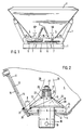
- den Schleuderdüngerstreuer in der Ansicht von hinten,
- Fig. 2
- die Anordnung des Rühr- und Ausbringorgans in der rechten Trichterspitze in der Ansicht von hinten, im Schnitt in in vergrößerter Darstellung,
- Fig. 3
- die Anordnung des Rühr- und Ausbringorgans in der Trichterspritze in gleicher Darstellungsweise,
- Fig. 4
- ein weiteres Rühr- und Ausbringorgan in gleicher Darstellungsweise,
- Fig. 5
- die Anordnung eines Rühr- und Ausbringorgans in gleicher Darstellungsweise,
- Fig. 6
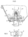
- die Anordnung des Auswerfers des Rühr- und Ausbringorgans in der Draufsicht nach abgenommenen Zubringkörper gemäß Fig. 5,
- Fig. 7
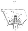
- die Anordnung des Rühr- und Ausbringkörpers gemäß Fig. 5, wobei der Ausbring- und Dosierkörper um 90° weitergedreht ist,
- Fig. 8
- die Anordnung des Rühr- und Ausbringkörpers in der Darstellung gemäß den vorstehenden Figuren,
- Fig. 9
- eine Anzahl von Auswerfern in Prinzipdarstellung in der Ansicht von hinten,
- Fig. 10
- ein weiteres Auswerferorgan in der Ansicht von hinten,
- Fig. 11
- der Auswerfer gemäß Fig. 10 in der Draufsicht,
- Fig. 12
- die Anordnung des Rühr- und Ausbringorgans mit einem weiteren Auswerferelement in der Darstellungsweise gemäß Fig. 5,
- Fig. 13
- die Anordnung des Auswerferelementes des Rühr- und Ausbringorgans in der Draufsicht nach abgenommenem Zubringerkörper gemäß Fig. 12 und
- Fig. 14
- die Anordnung des Rühr- und Ausbringorgans gemäß Fig. 12, wobei der Rühr- und Ausbringkörper um 90° weitergedreht ist.
- Fig. 1
- the centrifugal fertilizer spreader from behind,
- Fig. 2
- the arrangement of the stirring and dispensing element in the right-hand funnel tip in the view from behind, in section in an enlarged view,
- Fig. 3
- the arrangement of the stirring and dispensing element in the funnel syringe in the same representation,
- Fig. 4
- another stirrer and dispenser in the same Presentation,
- Fig. 5
- the arrangement of a stirring and dispensing element in the same representation,
- Fig. 6
- the arrangement of the ejector of the agitating and dispensing member in the plan view after the removed feed body according to FIG. 5,
- Fig. 7
- 5 the arrangement of the stirring and dispensing body, the dispensing and metering body being rotated further by 90 °,
- Fig. 8
- the arrangement of the stirring and dispensing body in the illustration according to the preceding figures,
- Fig. 9
- a number of ejectors in principle in the view from behind,
- Fig. 10
- another ejector organ in the view from behind,
- Fig. 11
- 10 in top view,
- Fig. 12
- the arrangement of the stirring and dispensing element with a further ejector element in the manner of illustration according to FIG. 5,
- Fig. 13
- the arrangement of the ejector element of the stirring and dispensing member in plan view after the feeder body according to FIG. 12 and
- Fig. 14
- the arrangement of the stirring and dispensing member according to FIG. 12, wherein the stirring and dispensing body is rotated through 90 °.
Der Schleuderdüngerstreuer weist den Rahmen 1 und den Vorratsbehälter 2 auf. Auf der Vorderseite des Rahmens 1 sind in bekannter und daher nicht dargestellter Weise Dreipunktkupplungselemente zum Anbau des Schleuderdüngerstreuers an den Dreipunktkrafthebers eines Schleppers angeordnet. Der Vorratsbehälter 2 ist durch das dachförmige Mittelteil 3 in die beiden Behälterspitzen 4 aufgeteilt. Unterhalb der Behälterspitzen 4 befindet sich jeweils eine Schleuderscheibe 5 und 6 die auf den Getriebeausgangswellen 7 eines Zahnradgetriebes 8 angeordnet sind und ineinander entgegengesetztem Drehsinn rotierend von einer Kraftquelle, beispielsweise eines Ölmotors oder der Zapfwelle des den Schleuderdüngerstreuer tragenden Schleppers, angetrieben werden. Die Schleuderscheibenantriebswelle ist mittels des Wellenstückes 10, welches auf die Antriebswelle 7 aufgesetzt ist, durch die sich im Vorratsbehälterboden 11 befindliche Durchtrittsöffnung 12 bis in die Trichterspitze 4 des Vorratsbehälters hineingeführt.The centrifugal fertilizer spreader has the frame 1 and the
In der schrägen Vorratsbehälterwand 13, die durch das dachförmige Mittelteil 3 gebildet wird, befindet sich die Austrittsöffnung 14. Vor der Austrittsöffnung 14 ist jeweils ein Schieber 15 angeordnet. Die beiden Schieber 15 sind unabhängig voneinander zu öffenen, so daß die Austrittsöffnungen 14 der beiden Trichterspitzen 7 unabhängig voneinander zu öffnen und zu schließen sind.The
Auf der Oberseite des Wellenstückes 10 ist ein Bolzen 16 mit gegenüber dem Wellenstück 10 reduziertem Durchmesser angeordnet. Am Ende des Bolzens 16 befindet sich der ebenfalls eine reduzierenden Durchmesser aufweisende Schraubbolzen 17.On the top of the
Auf dem Bolzen 16 des Wellenstückes 10 ist das Rühr- und Ausbringorgan 18 angeordnet, welches auch als Dosierorgan wirksam ist. Das Ausbringorgan 18 ist drehfest mit dem Wellenstück 10, welches wiederum über einen Stift 19 mit der Schleuderscheibenantriebswelle 7 verbunden ist, angeordnet. So wird das Rühr- und Ausbringorgan 18 mit der gleichen Drehzahl wie die Schleuderscheibens direkt angetrieben.On the
Das Ausbringorgan 18 befindet sich oberhalb des Behälterbodens 11 im Vorratsbehälter 2.The dispensing
Das Rühr- und Ausbringorgan 18 ist als rotationssymetrischer Ausbringkörper 20 ausgebildet, dessen größter Durchmesser A (60 150 mm, vorzugsweise 80 mm) jeweils in der Nähe und auf Höhe des untersten Bereiches und des kleinsten Öffnungsquerschnittes der jeweiligen Austrittsöffnung 14 liegt. Somit befinden sich die rotierenden Teile des Zubringkörpers 20 im Düngerraum, also im unteren Vorratsbehälterbereich sowohl oberhalb als auch unterhalb dieses größten Durchmessers A des Ausbringkörpers rotierende Teile, und zwar derartig, daß die von dem Wellenstück 10 gebildete Antriebswelle, welche von unten durch den Behälterboden 11 hindurchragt und den Ausbringkörper 18 antreibt, einen wesentlich kleineren Durchmesser B als der jeweilige Zubringkörper 20 an seiner größten Ausdehnung (Durchmesser A) aufweist.The stirring and dispensing
Der Ausbringkörper 20 weist eine völlig glatte Oberfläche auf. Desweiteren besitzt der Ausbringkörper eine kegelige Form, dessen Spitze 22 nach oben gerichtet ist. Die Außenfläche 23 des kegeligen Ausbringkörpers 20 schließen ein sich nach unten öffnenden Winkel α von etwa 60 - 120°, vorzugsweise 90° zueinander ein.The
Zwischen der Unterseite 24 des Ausbringkörpers 20 an seiner größten radialen Ausdehnung und dem Behälterboden 11 ist ein Abstand C von mindestens 8 mm, vorzugsweise 10 mm vorhanden.There is a distance C of at least 8 mm, preferably 10 mm, between the
Desweiteren befindet sich zwischen der größten radialen Ausdehnung des Ausbringkörpers 20 und der Vorratsbehälterwand 13, in welcher sich die Austrittsöffnungen 14 befinden, ein Abstand D von nicht mehr als 40 mm.Furthermore, there is no distance D of between the greatest radial extent of the dispensing
Oberhalb des Ausbringkörpers 20 ist auf dem Schraubbolzen eine Gummifeder 25 angeordnet, wobei sich zwischen der Gummifeder und dem Schraubbolzen 17 eine Rohrhülse befindet. Insgesamt ist der Zubringerkörper 20 mittels der Schraube 27 gesichert.A
Sowohl der Ausbringkörper 20 wie auch der Boden 11 sind leicht lösbar und auswechselbar ausgebildet, so daß der Boden 11 nach Abnahme des Zubringkörpers 20 nach oben abgenommen und falls erforderlich ersetzt werden kann.Both the dispensing
Die Funktionsweise des Ausbringkörpers 20 ist folgende:
Der Düngerstrom, der von oben nach unten auf den Zubringkörper 20 nachfließt, wird schonend, wie durch die Pfeile 28 und 29 angedeutet ist, aufgeteilt und granulatschonend in Pfeilrichtung 28 und 29 zur Austrittsöffnung 14 geleitet. Hierbei ist der Ausbringkörper 20, welcher das Dsier- und Ausbringorgan sowie eine Art Rührkörper bildet, so ausgelegt, daß selbst, wenn die Austrittsöffnung 14 durch den Schieber 15 längere Zeit während des Betriebes, d.h. wenn der Ausbringkörper 20 mit der gleichen Drehzahl wie die Schleuderscheiben 5 rotiert, der Dünger nicht zermalmt wird und nicht zusammenbackt. Es entsteht also keine feste Düngerwand vor der Austrittsöffnung 14. Selbst nach langer Arbeitszeit bei einseitigem Streuen, wenn beispielsweise nur einseitig nach links gestreut werden soll, so daß die rechte Austrittsöffnung geschlossen ist, wird nach dem Öffnen der Austrittsöffnung 14 sofort Dünger durch die Austrittsöffnung 14 ausgebracht. Falls sich dennoch ein kleiner weicher Düngerring vor der Austrittsöffnung 14 gebildet haben sollte, welches bei sich extrem verhaltenden Düngersorten bei schlechten Witterungs- und Lagerbedingungen möglich ist, wird dieser durch das sich am Schieber 15 befindliche, und beispielsweise von einer Schraube 30 gebildete Verdrängerelement aufgelöst. Im übrigen ist der Schieber in Fig. 2 in der Stellung gezeichnet, in der die Austrittsöffnung 14 verschlossen ist.The operation of the dispensing
The fertilizer flow, which flows from top to bottom onto the
Die Fig. 3 zeigt eine andere Ausbildung des Ausbringkörpers. Dieser Ausbringkörper 31 weist an sich ebenfalls wieder eine kegelige Form auf, mit einer fast glatten Oberfläche. Einseitig ist eine kleine Erhebung 32 aufgesetzt, die sich nach unten zum Auswerfer 33 ausbildet. Dieser Auswerfer 33 überragt einseitig den Zubringerkörper 31 in der Nähe seines größten Durchmessers A. Der Auswerfer 33 überragt den Ausbringkörpers um das Maß E, welches etwa 10 mm beträgt.3 shows another embodiment of the dispensing body. This dispensing
Zwischen der größten radialen Ausdehnung des Auswerfers 32 und der Vorratsbehälterwand 13, in welcher sich die Austrittsöffnung 14 befindet, ist ein Abstand F vorhanden, der weniger als 25 mm beträgt.Between the largest radial extent of the
Der Ausbringkörper 31 mit dem Auswerfer 32 ist elastisch nach oben und entgegen der Drehrichtung ausweichbar auf der Antriebswelle 10 mittels einer nicht näher dargestellten Überlastsicherung angeordnet.The dispensing
Selbstverständlich ist es möglich, den Auswerfer 31 gemäß Fig. 3, falls es die Einsatzbedingungen erfordern, gegen den Ausbringkörper 20 gemäß Fig. 2 auszutauschen.Of course, it is possible to replace the
Durch den Auswerfer 33 wird gewährleistet, daß sich beispielsweise in der Austrittsöffnung 14', welche durch den Schieber 15 freigegeben ist, festsetzende Kluten 34 zerdrückt bzw. zerschlagen werden, so daß die Austrittsöffnung 14' von den Auswerfern 33 freigehalten wird.The
Der Ausbringkörper 35 gemäß Fig. 4 weist wieder um eine kegelige Form auf. In der Unterseite des Ausbringkörpers 35 ist eine Nut 36 angeordnet, in welcher sich der Auswerfer 37 befindet. Über den Stift 38 ist der Auswerfer 37 und der Ausbringkörper 35 drehfest mit dem Wellenstück 10, welches über den Stift 19 mit der Schleuderscheibenantriebswelle 7 drehfest verbunden ist, drehfest verbunden.The dispensing
Der Auswerfer 37 überragt den Ausbringkörper auf seiner Unterseite in seiner größten Ausdehnung mit dem Auswerferfinger 38. Dieser Auswerferfinger 39 kann rechtwinklig zu der Drehachse des Zubringers 35 angeordnet sein, oder, wie durch die mit strichpunktierten Linien angedeutet, in Position 39' nach unten abgebogen sein.The ejector 37 projects beyond its greatest extent with the ejector finger 38 on its underside. This
Das Rühr- und Ausbringorgan gemäß Fig. 5 ist als Ausbringkörper 40 ausgebildet. Der Ausbringkörper 40 weist eine kegelige Form auf. Der Ausbringkörper 40 weist auf seiner Unterseite eine quer verlaufende Längsnut 41 auf, in welcher der Auswerfer 42 eingelegt ist. Desweiteren weist das Wellenstück 10 auf seiner Oberseite ebenfalls die eingefräste Quernut 43 auf. Diese Quernut 43 weist die schrägen Seitenwände 44 auf. In diese Quernut 43 ist ebenfalls der Auswerfer 42 eingelegt. Der Auswerfer 42 weist in der Mitte die Bohrung 45 auf, mittels welcher er von oben auf den Bolzen 16 aufgesteckt werden kann. Ebenfalls weist der Ausbringkörper 40 die Bohrung 46 auf, mittels welcher er ebenfalls von oben auf den Bolzen 16 aufgesteckt ist. Der Schraubbolzen 26 weist gegenüber dem Bolzen 16 einen reduzierten Durchmesser auf. Auf den Schraubbolzen 26 ist zunächst die Rohrhülse 26 aufgesteckt. Auf diese Rohrhülse 26 ist die Gummifeder 25 aufgesteckt. Mittels der Scheibe 47 und der Mutter 27 sind sämtliche Teile gesichert. Durch die Gummifeder 25 können der Auswerfer 42 und der Ausbringkörper 40 elastisch nach oben ausweichen. In Verbindung mit der Quernut 43 und den schrägen Wänden 44 ergibt sich somit eine Überlastsicherung, d.h. wenn ein unzerdrückbarer Gegenstand die ungehinderte Rotation des Auswerfers 42 behindert, springt der Auswerfer 42 aus der Nut 43 aufgrund der schrägen Wände 44 nach oben, wobei die Gummifeder 25 zusammengedrückt wird.5 is designed as a dispensing
Der Auswerfer 42 überragt den Ausbringkörper 40 in der Nähe seines größten Durchmessers A beidseitig mit den Auswerferfingern 48 und 49. Die äußeren Enden der Auswerferfinger 48 und 49 überragen den Ausbringkörper 40 bezüglich seines größten Durchmessers A um nicht mehr als 15 mm, vorzugsweise nur um 5 - 10 mm.The
Der Ausbringkörper 40 weist eine kegelige Form auf, dessen Spitze nach oben gerichtet ist.The dispensing
Zwischen dem Ausbringkörper 40 an seiner größten radialen Ausdehnung A und dem Behälterboden 11 ist ein Abstand C von mindestens 8 mm, vorzugsweise mehr als 10 mm vorhanden. Somit ist hier ein Abstand C vorhanden, der größer als der mittlere Durchmesser der Korngröße des auszubringenden Düngers ist. Somit können keine Düngerkörner nachteilig zerdrückt werden.There is a distance C of at least 8 mm, preferably more than 10 mm, between the dispensing
Zwischen der größten radialen Ausdehnung des Ausbringerkörpers 40 und der Vorratsbehälterwand 13, in welcher sich die Austrittsöffnungen 14 befinden, ist ein Abstand D von nicht mehr als 40 mm vorhanden. Zwischen der größten radialen Ausdehnung des Auswerfers 42, welche von den Auswerferfingern 48 und 49 gebildet werden, und der Vorratsbehälter 13, in welcher sich die Austrittsöffnungen 14 befinden, ist ein Abstand von mehr als 25 mm vorhanden.There is a distance D of no more than 40 mm between the greatest radial extent of the
Wie bereits vor geschildert, ist der Auswerfer 42 elastisch nach oben und entgegen der Drehrichtung ausweichbar mittels einer Überlastsicherung auf seiner Antriebswelle 10 angeordnet.As already described before, the
Der Auswerfer 42 ist aus Stahl, vorzugsweise einem hochfesten und nichtrostendem Stahl hergestellt. Der Ausbringkörper 40 kann beispielsweise als Kunststoffteil aus Kunststoff hergestellt sein. Desweiteren ist der Auswerfer und der Ausbringkörper 40 leicht lösbar und auswechselbar auf der Antriebswelle 10 befestigt.The
Anhand der Fig. 8 und 9 soll nun aufgezeigt werden, daß unterschiedliche Auswerfer im Zusammenhang mit dem Ausbringkörper einzusetzen sind. Die einzelnen Formen werden im Folgenden kurz beschrieben.8 and 9 will now show that different ejectors are to be used in connection with the dispensing body. The individual forms are briefly described below.
Die Fig. 8 zeigt zunächst einen Ausbringkörper 40 und einen Auswerfer 42 mit den Auswerferfingern 48 und 49 gemäß Fig. 5 bis 7. Die Enden der Auswerferfinger 48 und 49 können beispielsweise mit einer Aufpanzerung 51 versehen sein, um so die Standseite des Auswerfers wesentlich erhöhen zu können.8 first shows a
Der Auswerfer 42 kann gegen einen Auswerfer 52 ausgetauscht werden, dessen den Ausbringkörper 40 an seiner größten radialen Ausdehnung überragenden Auswerferfingers 53 in gleicher Ebene wie der übrige Teil des Auswerfers 52 ligen.The
Bei dem Auswerfer 52 sind die Auswerferfinger 53 entweder auf der Ober- oder auf der Unterseite mit einer Aufpanzerung 51 versehen. Der Auswerfer 54 unterscheidet sich von dem Auswerfer 52 dadurch, daß die Auswerferfinger 53 beidseitig mit einer Aufpanzerung versehen sind und eine geringfügig größere Lage aufweisen. Der Auswerfer 55 unterscheidet sich von den Auswerfern 54 und 52 dadurch, daß die Auswerferfinger 53 auf ihrer Stirnseite mit einer Aufpanzerung versehen sind. Der Auswerfer 56 überragt den Ausbringkörper 40 nur einseitig mit dem Auswerferfinger 57. Dieser Auswerferfinger 57 ist auf seiner Stirnseite mit einer Aufpanzerung 51 versehen. Der Auswerfer 58 unterscheidet sich von dem Auswerfer 56 dadurch, daß der Auswerferfinger 57 auf seiner ober- und Unterseite mit einer Aufpanzerung versehen ist.In the
Der Auswerfer 59 überragt einseitig mit dem Auswerferfinger 60, der nach oben abgebogen ist den Zubringerkörper 40.The
Der Auswerfer 61, dessen Auswerferfinger 62 nach unten umgebogen ist, überragt ebenfalls nur einseitig den Zubringerkörper 40 an seiner größten radialen Ausdehnung.The
Die Fig. 10 und 11 zeigen den Auswerfer 63, der mit seinen Auswerferfingern 64,65,66 und 67 den Ausbringkörper 40 an seiner radialen größten Ausdehnung überragt. Die Auswerferfinger 64 und 66 sowie 65 und 67 sind jeweils durch eine Aussparung 68 entstanden. Der Auswerfer 63 weist auf jeder dem Ausbringkörper 40 überragenden Seite jeweils zwei Auswerferfinger, nämlich 64 und 66 sowie 65 und 67 auf, wobei auf jeder Seite des Zubringerkörpers 40 der eine Finger 64 und 65 nach oben und der andere Finger 66 und 67 nach unten umgebogen sind. Hierbei sind die auf der längeren Seite gerade unmittelbar gegenüberliegende Finger 64 und 65 gemeinsam nach oben und die gerade gegenüberliegenden Finger 66 und 67 gemeinsam nach unten umgebogen. Hierdurch ist es möglich, selbst bei in entgegengesetztem Drehsinn rotierenden Schleuderscheiben 5 und Auswerfern sowie Zubringkörpern 40 gemäß Drehrichtung 50 und 50' gleich auszubilden, weil die Auswerferfinger spiegelbildlich ausgebildet sind.10 and 11 show the
Wenn der Auswerfer 63 zusammen mit dem Zubringkörper 40 eingesetzt wird, ist darauf zu achten, daß das Verdränger- oder Aufbrechelement 30 an dem Schieber so angeordnet ist, daß sich das Verdränger- und Aufbrechelement 30 sich auf Höhe des Auswerfers derart befindet, daß das Verdränger- und Aufbrechelement 30 sich in Richtung in auf Höhe der Spreizung 69 der Auswerferfinger 64,65,66 und 67 befindet.If the
Zum Schluß sei darauf hingewiesen, daß die verschiedenen Auswerfer leicht gegeneinander ausgetauscht werden können, wenn es die Einsatzverhältnisse erfordern.Finally, it should be pointed out that the various ejectors can easily be exchanged for one another if the operating conditions so require.
Das Ausbring- und Dosieroragn 70 gemäß Fig. 12 unterscheidet sich von dem Ausbring- und Dosierorgan gemäß Fig. 5 dauch eine andere Ausbildung des Auswerfers. Dieser Auswerfer 71 ist unterhalb des Ausbringkörpers 40, der eine kegelstumpfförmige Form aufweist, in der sich im Ausbringkörper 40 befindlichen Längsnut 41 eingelegt. Der Auswerfer 71 weist in der Mitte die Bohrung 45 auf, mittels welcher er von oben auf den Bolzen 16 aufgesteckt ist. Das Längenmaß E des Auswerfers 71 entspricht in etwa dem größten Durchmesser A des Ausbringkörpers 40. Die äußeren Enden, d.h. die Auswerferfinger 72 des Auswerfers sind beidseitig nach unten abgebogen. Hierbei können die äußersten Breitseitenteile 72' der Auswerferfinder 72 etwas, beispielsweise um etwa 2 mm über die äußere untere Kontur des Ausbringkörpers 40 in der Draufsicht überstehen. Die Oberfläche des Ausbringkörpers 40 ist auf seiner kegelstumpfförmigen Oberseite völlig glatt. Der Zwischenraum 73 zwischen der Wand 13, in der sich die Auslauföffnung 14 befindet, und dem Ausbringkörper 40 ist trichter- bzw. keilförmig ausgebildet.The dispensing and metering element 70 according to FIG. 12 differs from the dispensing and metering element according to FIG. 5 in that the ejector is designed differently. This
Der Auswerfer 71 ist aus Stahl hergestellt. Der Ausbringkörper 40 ist aus einem harten Kunststoff hergestellt, damit die Oberfläche möglicht lange glatt bleibt.The
Als besonders vorteilhaft hat sich gezeigt, den Durchmesser A und das Längenmaß E in einer Größe von ca. 80 mm zu wählen, weil hier der beste Kompromiß zwischen ausreichender Düngerförder- und Rührwirkung einerseits und dem Nichtzusammenbacken des Düngers sowie ausreichend schonender Behandlung des Düngers andererseits besteht. Der Dünger fließt dann gleichmäßig und ruhig aus der Auslauföffnung 14 heraus.It has proven to be particularly advantageous to choose the diameter A and the length dimension E in a size of approx. 80 mm, because here the best compromise exists between sufficient fertilizer delivery and stirring action on the one hand and the non-caking of the fertilizer and sufficient gentle treatment of the fertilizer on the other . The fertilizer then flows out evenly and calmly the outlet opening 14 out.
Die Funktionsweise des Ausbringkörpers 40 in Verbindung mit dem Auswerfer 71 gemäß Fig. 12 ist folgende:
Der Düngerstrom, der von oben nach unten auf den Ausbringkörper 40 nachfließt, wird schonend, wie durch die Pfeile 28 und 29 angedeutet ist, aufgeteilt und granulatschonend in Pfeilrichtung 28 und 29 zur Austrittsöffnung 14 geleitet. Hierbei ist der Ausbringkörper 40, welcher das Dosier- und Ausbringorgan sowie eine Art Rührkörper bildet zusammen mit dem Auswerfer 71, so ausgelegt, daß selbst, wenn die Austrittsöffnung 14 durch den Schieber 15 längere Zeit während des Betriebes, d.h. wenn der Ausbringkörper 40 mit der gleichen Drehzahl wie die Schleuderscheiben 5 rotiert, der Dünger nicht zermalmt wird und nicht zusammenbackt Es entsteht also keine feste Düngerwand vor der Austrittsöffnung 14. Selbst nach langer Arbeitszeit bei einseitigem Streuen, wenn beispielsweise nur einseitig nach links gestreut werden soll, so daß die rechte Austrittsöffnung geschlossen ist, wird nach dem Öffnen der Austrittsöffnung 14 sofort Dünger durch die Austrittsöffnung 14 ausgebracht. Der Auswerfer 71 mit Auswerferfingern 72 unterstützt das Ausbringen des Düngers sowie dessen Förderung in Richtung der Auslauföffnung in äußerst granulatschonender Weise. Weiterhin sorgt der Auswerfer 71 mit einen Auswerferfingern 72 für eine vollständige Entleerung des Vorratsbehälters, so daß keine Restmengen im Vorratsbehälter bleiben.The way in which the dispensing
The fertilizer flow, which flows from top to bottom onto the spreading
Claims (47)
- Centrifugal fertiliser broadcaster, including a hopper and at least two rotatably driven centrifugal discs, the fertilisers which are to be distributed and are situated in the hopper having to be supplied to said centrifugal discs through outlet apertures which are to be opened and closed and are situated in the hopper walls, which are preferably inclined or extend upwardly, said fertilisers being supplied via rotatably driven agitating and distributing members, which are situated in the lower region of the hopper and are situated above the base of the hopper, the agitating and distributing members being driven directly via the drive shafts, which are guided through the base of the hopper, at the same speed as the centrifugal discs and comprising at least substantially rotationally symmetrical distributing members (20, 31, 35, 40), the agitating and distributing members having a configuration which is at least approximately conical or frustoconical, the greatest diameter (A) of the distributing member (20, 31, 35, 40) being situated on its underside, at least one ejector member (33, 37, 42, 52, 54, 55, 56, 58, 59, 61, 63) protruding beyond the respective distributing member (20, 31, 35, 40) in the vicinity of its greatest diameter (A), characterised in that the ejector member (33, 37, 42, 52, 54, 55, 56, 58, 59, 61, 63) protrudes no more than 15 mm beyond the distributing member (20, 31, 35, 40) in respect of its greatest diameter (A), and in that there is a spacing (D) of no more than 40 mm between the greatest radial extent (A) of the distributing member (20, 31, 35, 40) and the hopper wall (13), in which the outlet apertures (14) are provided.
- Centrifugal fertiliser broadcaster according to claim 1, characterised in that the distributing member (20, 31, 35, 40) is provided on its underside with the ejector member (33, 37, 42, 52, 54, 55, 56, 58, 59, 61, 63, 71).
- Centrifugal fertiliser broadcaster according to one or more of the preceding claims, characterised in that the agitating and distributing members (18) comprise at least substantially rotationally symmetrical distributing members (20, 31, 35, 40), the greatest diameter (A) of which lies respectively in the vicinity of and/or substantially on a level with the lower and/or lowermost region and/or the small and/or smallest cross-sections of opening of the respective outlet apertures (14, 14'), rotating members being situated in the fertiliser chamber, that is to say in the lower region of the hopper above this greatest diameter of the distributing member (20, 31, 35, 40), said rotating members having a substantially smaller diameter (B) (preferably not greater than half the greatest diameter (A) of the distributing member (20, 31, 35, 40) than the respective distributing member (20, 31, 35, 40) at its greatest extent (A).
- Centrifugal fertiliser broadcaster according to one or more of the preceding claims, characterised in that rotating members are situated in the fertiliser chamber, that is to say in the lower region of the hopper above this greatest diameter (A) of the distributing member (20, 31, 35, 40), in such a manner that the drive shaft (10), which protrudes through the hopper base (12) from below and drives the metering and distributing members (18, 20, 31, 35, 40), has a substantially smaller diameter (B), preferably not greater than half the greatest diameter (A) of the distributing member (20, 31, 35, 40) than the respective distributing member (20, 31, 35, 40) at its greatest extent (A).
- Centrifugal fertiliser broadcaster according to one or more of the preceding claims, characterised in that the respective distributing member (20, 31, 35, 40) has a surface (23) which is at least substantially entirely smooth or is only provided with very small raised portions (32).
- Centrifugal fertiliser broadcaster according to one or more of the preceding claims, characterised in that the distributing member (20, 31, 35, 40) has a smooth surface (23).
- Centrifugal fertiliser broadcaster according to one or more of the preceding claims, characterised in that the length dimension (E) of the ejector member (71) corresponds substantially to the greatest diameter (A) of the distributing member (40).
- Centrifugal fertiliser broadcaster according to one or more of the preceding claims, characterised in that the length dimension of the ejector member is smaller than the greatest diameter of the distributing member.
- Centrifugal fertiliser broadcaster according to one or more of the preceding claims, characterised in that the distributing member (20, 31, 35, 40) has a conical or frustoconical configuration, the apex (22) of which is upwardly orientated.
- Centrifugal fertiliser broadcaster according to one or more of the preceding claims, characterised in that the external surfaces (23) of the conical distributing member (20, 31, 35, 40) form an angle, which opens downwardly and corresponds substantially to between 60 and 120°, preferably 90°.
- Centrifugal fertiliser broadcaster according to one or more of the preceding claims, characterised in that there is a considerable vertical spacing between the distributing member (20, 31, 35, 40) at its greatest radial extent (A) and the hopper base (11), this spacing (C) being at least 8 mm, and preferably more than 10 mm.
- Centrifugal fertiliser broadcaster according to one or more of the preceding claims, characterised in that there is a spacing (F) of more than 25 mm between the greatest radial extent (A) of the ejector member (33, 37, 42, 52, 54, 55, 56, 58, 59, 61, 63) and the hopper wall (13), in which the outlet apertures (14) are provided.
- Centrifugal fertiliser broadcaster according to one or more of the preceding claims, characterised in that the ejector member (33, 37, 42, 52, 54, 55, 58, 56, 59, 61, 63) is secured on the drive shaft (10) by means of an overload prevention means.
- Centrifugal fertiliser broadcaster according to one or more of the preceding claims, characterised in that the ejector member (33, 37, 42, 52, 54, 55, 56, 58, 59, 61, 63) is disposed beneath the distributing member (20, 31, 35, 40).
- Centrifugal fertiliser broadcaster according to one or more of the preceding claims, characterised in that the ejector member (33, 37, 42, 52, 54, 55, 56, 58, 59, 61, 63) is disposed on the drive shaft (10) so as to be resiliently yieldable upwardly and/or in opposition to the direction of rotation (50, 50').
- Centrifugal fertiliser broadcaster according to one or more of the preceding claims, characterised in that the ejector member (33, 37, 42, 52, 54, 55, 56, 58, 59, 61, 63) is formed from steel, preferably from a high-tensile and/or stainless steel, preferably provided with an additional reinforcement (51).
- Centrifugal fertiliser broadcaster according to one or more of the preceding claims, characterised in that the distributing member (20, 31, 35, 40) itself is resilient.
- Centrifugal fertiliser broadcaster according to one or more of the preceding claims, characterised in that the distributing member (20, 31, 35, 40) is formed as a plastics material component part.
- Centrifugal fertiliser broadcaster according to one or more of the preceding claims, characterised in that a spring (25), formed from rubber for example, is disposed above the distributing member (20, 31, 35, 40).
- Centrifugal fertiliser broadcaster according to one or more of the preceding claims, characterised in that a spacer tube (26) is provided internally of the rubber spring (25).
- Centrifugal fertiliser broadcaster according to one or more of the preceding claims, characterised in that the ejector member (33, 37, 42, 52, 54, 55, 56, 58, 59, 61, 63) is interchangeably disposed on the drive shaft (10).
- Centrifugal fertiliser broadcaster according to one or more of the preceding claims, characterised in that the distributing member (35, 40) is provided, on its underside, with a recessed groove (36, 43), in which the ejector member (33, 37, 42, 52, 54, 55, 56, 58, 59, 61, 63) engages.
- Centrifugal fertiliser broadcaster according to one or more of the preceding claims, characterised in that the distributing member (20, 31, 35, 40) is non-rotatably connected to the respective drive shaft (10).
- Centrifugal fertiliser broadcaster according to one or more of the preceding claims, characterised in that the ejector member (33, 37, 42, 52, 54, 55, 56, 58, 59, 61, 63) is connected to the drive shaft (10) in a non-rotatable manner, but preferably with an overload prevention means.
- Centrifugal fertiliser broadcaster according to one or more of the preceding claims, characterised in that the ejector member (37, 56, 58, 59, 61) protrudes unilaterally beyond the greatest extent (A) of the distributing member (20, 31, 35, 40).
- Centrifugal fertiliser broadcaster according to one or more of the preceding claims, characterised in that the ejector member (42, 52, 54, 55) protrudes beyond the distributing member (40) bilaterally on diametrically opposed sides of the distributing member (20) with small spacings (E).
- Centrifugal fertiliser broadcaster according to one or more of the preceding claims, characterised in that the ejector member (37, 52, 54, 55, 56) is provided horizontally and at right angles relative to the drive shaft (10) in its region protruding beyond the distributing member (35, 40).
- Centrifugal fertiliser broadcaster according to one or more of the preceding claims, characterised in that the region (A) of the ejector member (37, 42, 59, 61, 63) protruding beyond the greatest region (A) of the distributing member (35, 40) is bent inclinedly upwardly and/or downwardly.
- Centrifugal fertiliser broadcaster according to one or more of the preceding claims, characterised in that the ejector member (42, 63) is bent downwardly on one side and bent upwardly on the other side.
- Centrifugal fertiliser broadcaster according to one or more of the preceding claims, characterised in that the ejector member (63) has two ejector fingers (64, 65, 66, 67) on each side protruding beyond the distributing member (40), one finger (64, 65) being bent upwardly and the other finger (66, 67) being bent downwardly on each side.
- Centrifugal fertiliser broadcaster according to one or more of the preceding claims, characterised in that the fingers (64, 65), which lie exactly opposite each other on the longer side, are jointly bent upwardly or the fingers (66, 67) are jointly bent downwardly.
- Centrifugal fertiliser broadcaster according to one or more of the preceding claims, characterised in that all of the ejector members (33, 37, 42, 52, 54, 55, 56, 58, 59, 61, 63) have identical configurations.
- Centrifugal fertiliser broadcaster according to one or more of the preceding claims, characterised in that the two ends (72) of the ejector member (71) point downwardly.
- Centrifugal fertiliser broadcaster according to one or more of the preceding claims, characterised in that the through-apertures (12), through which the drive shafts (10) are guided for driving the distributing members (20, 31, 35, 40), have a substantially smaller diameter than the distributing members (20, 31, 35, 40) in respect of their greatest extent (A).
- Centrifugal fertiliser broadcaster according to one or more of the preceding claims, characterised in that the ejector members (33, 37, 42, 52, 54, 55, 56, 58, 59, 61, 63) and/or distributing members (20, 31, 35, 40) are disposed on their respective drive shaft (10) in an easily interchangeable manner.
- Centrifugal fertiliser broadcaster according to one or more of the preceding claims, characterised in that the base plates (11) are disposed internally of the hopper (2) in an easily detachable manner and are disposed so as to be upwardly removable.
- Centrifugal fertiliser broadcaster according to one or more of the preceding claims, characterised in that shutters (15) are disposed in front of the outlet apertures (14), and a displacement and/or fracturing element (30) is disposed on the side of the shutters facing the outlet apertures (14) and the hopper interior in the region of the smallest aperture, said element being situated on a level with the ejector member (33, 37, 42, 52, 54, 55, 56, 58, 59, 61, 63) and/or on the greatest extent of the distributing member (20, 31, 35, 40).
- Centrifugal fertiliser broadcaster according to one or more of the preceding claims, characterised in that the drive shaft is formed by a shaft portion (10), which is mounted upon the centrifugal disc drive shaft (7) and is guided through the hopper base (11), and the drive shaft is provided on its upper surface with the distributing member (20, 31, 35, 40) and/or ejector member (33, 37, 42, 52, 54, 55, 56, 58, 59, 61, 63).
- Centrifugal fertiliser broadcaster according to one or more of the preceding claims, characterised in that the extension member (10) has an overload prevention means above the hopper base (11).
- Centrifugal fertiliser broadcaster according to one or more of the preceding claims, characterised in that the overload prevention means is a horizontally extending groove (43), which is provided with inclined walls (44) and in which the ejector member (42, 52, 54, 55, 56, 58, 59, 61, 63), formed from flat material, engages, in that the distributing member (20, 31, 35, 40) is deposited onto the shaft (10) above the ejector member (33, 37, 42, 52, 54, 55, 56, 58, 59, 61, 63), and in that a spring, for example a rubber spring (25), is situated above the distributing member (20, 31, 35, 40).
- Centrifugal fertiliser broadcaster according to one or more of the preceding claims, characterised in that the ejector member (33) is integrally formed with the distributing member (31).
- Centrifugal fertiliser broadcaster according to one or more of the preceding claims, characterised in that the ejector member (33) is mounted from above upon the upper face of the distributing member (31), more especially upon the conical face of the distributing member (31), which face extends inclinedly downwardly.
- Centrifugal fertiliser broadcaster according to one or more of the preceding claims, characterised in that the fingers (48, 49, 64, 65, 66, 67) of the ejector member (42, 63) are bent in such a manner that one finger (49, 66, 67) is situated above the displacement element (30) and the other finger is situated beneath said element.
- Centrifugal fertiliser broadcaster according to one or more of the preceding claims, characterised in that variously configured ejector members (33, 37, 42, 52, 54, 55, 56, 58, 59, 61, 63) and/or distributing members (20, 31, 35, 40) are provided and interchangeable with one another.
- Centrifugal fertiliser broadcaster according to one or more of the preceding claims, characterised in that the agitating and distributing members are disposed in the hopper above the base thereof.
- Centrifugal fertiliser broadcaster according to one or more of the preceding claims, characterised in that the gap (73) between the wall (13), in which the outlet aperture (14) is provided, and the distributing member (40) has a funnel-like or wedge-shaped configuration.
- Centrifugal fertiliser broadcaster according to one or more of the preceding claims, characterised in that substantially only the outermost broadside portions (72') of the ejector fingers (72) protrude beyond the outer, lower configuration of the distributing member (40).
Applications Claiming Priority (2)
| Application Number | Priority Date | Filing Date | Title |
|---|---|---|---|
| DE4002408 | 1990-01-27 | ||
| DE4002408A DE4002408A1 (en) | 1990-01-27 | 1990-01-27 | SLINGER SPREADER |
Publications (3)
| Publication Number | Publication Date |
|---|---|
| EP0439718A2 EP0439718A2 (en) | 1991-08-07 |
| EP0439718A3 EP0439718A3 (en) | 1991-09-18 |
| EP0439718B1 true EP0439718B1 (en) | 1995-03-01 |
Family
ID=6398908
Family Applications (1)
| Application Number | Title | Priority Date | Filing Date |
|---|---|---|---|
| EP90123029A Expired - Lifetime EP0439718B1 (en) | 1990-01-27 | 1990-12-01 | Broadcaster |
Country Status (2)
| Country | Link |
|---|---|
| EP (1) | EP0439718B1 (en) |
| DE (2) | DE4002408A1 (en) |
Families Citing this family (2)
| Publication number | Priority date | Publication date | Assignee | Title |
|---|---|---|---|---|
| US6499679B1 (en) | 1997-12-04 | 2002-12-31 | Basf Aktiengesellschaft | Granular spreader and product container |
| ITNA20040059A1 (en) * | 2004-10-25 | 2005-01-25 | Errico Pietro D | DOSER FOR DUST AND / OR GRANULAR CENTRIFUGAL ACTION FOR INDUSTRIAL AND CIVIL USE. |
Family Cites Families (6)
| Publication number | Priority date | Publication date | Assignee | Title |
|---|---|---|---|---|
| FR1148263A (en) * | 1956-04-28 | 1957-12-05 | fertilizer spreader | |
| DE2804253A1 (en) * | 1978-02-01 | 1979-08-02 | Amazonen Werke Dreyer H | Twin outlet fertilizer spinner - has agitators mounted separately from discs to be driven at slower speed |
| NL8103896A (en) * | 1981-08-21 | 1983-03-16 | Lely Nv C Van Der | DEVICE FOR SPREADING GRAIN AND / OR POWDER MATERIAL. |
| NL8105663A (en) * | 1981-11-03 | 1983-06-01 | Lely Nv C Van Der | DEVICE FOR SPREADING GRAIN AND / OR POWDER MATERIAL. |
| DE8632954U1 (en) * | 1986-12-09 | 1987-05-21 | Weichs, Hermann, 8267 Neumarkt-St Veit, De | |
| FR2617000B1 (en) * | 1987-06-29 | 1990-09-28 | Nicephore Niepce Lycee Enseig | REGULAR FEED FOR GRANULAR PRODUCT SPREADER |
-
1990
- 1990-01-27 DE DE4002408A patent/DE4002408A1/en not_active Withdrawn
- 1990-12-01 DE DE59008595T patent/DE59008595D1/en not_active Expired - Fee Related
- 1990-12-01 EP EP90123029A patent/EP0439718B1/en not_active Expired - Lifetime
Also Published As
| Publication number | Publication date |
|---|---|
| DE4002408A1 (en) | 1991-08-01 |
| EP0439718A2 (en) | 1991-08-07 |
| EP0439718A3 (en) | 1991-09-18 |
| DE59008595D1 (en) | 1995-04-06 |
Similar Documents
| Publication | Publication Date | Title |
|---|---|---|
| EP0580026B1 (en) | Mower with cutter-housing and rearward ejection shaft with directing device | |
| DE2835011B1 (en) | Centrifugal broadcaster, especially for granular fertilizers | |
| EP0192085B1 (en) | Two disc fertilizer spreader | |
| EP0532055A2 (en) | Distributing method for fertilizer with a broadcaster spreader | |
| DE3804412A1 (en) | SLINGER SPREADER | |
| DE19813980B4 (en) | Single-axle spreading trolley | |
| DE3532756C1 (en) | Broadcaster, especially for granular fertilizers | |
| EP0927511A2 (en) | Apparatus for adjustment of the distribution rate | |
| EP0439718B1 (en) | Broadcaster | |
| DE3337762A1 (en) | METHOD FOR APPLYING DISPENSER | |
| EP0427936B1 (en) | Fertilizer broadcaster | |
| EP0429864B2 (en) | Centrifugal fertilizer spreader | |
| EP0313995B1 (en) | Spreader, especially a disc spreader for fertilizers | |
| DE3442465A1 (en) | SPREADER, ESPECIALLY MINERAL GROUNDING SPREADER | |
| DE3533586C2 (en) | ||
| EP0292874B1 (en) | Large capacity fertilizer broadcaster | |
| EP0385091A2 (en) | Broadcaster | |
| DE3736865A1 (en) | Spreading appliance, especially fertiliser broadcaster | |
| EP0853871B1 (en) | Centrifugal spreader | |
| DE4020574A1 (en) | Centrifugal fertiliser spreader with frame and hopper | |
| EP0356770B1 (en) | Spinning fertilizer distributors | |
| DE1924631C3 (en) | Spreader | |
| DE19606586A1 (en) | Centrifugal fertilizer spreader | |
| DE3608935A1 (en) | SLINGER | |
| DE3917449C2 (en) |
Legal Events
| Date | Code | Title | Description |
|---|---|---|---|
| PUAI | Public reference made under article 153(3) epc to a published international application that has entered the european phase |
Free format text: ORIGINAL CODE: 0009012 |
|
| PUAL | Search report despatched |
Free format text: ORIGINAL CODE: 0009013 |
|
| AK | Designated contracting states |
Kind code of ref document: A2 Designated state(s): CH DE DK ES FR GB IT LI NL |
|
| AK | Designated contracting states |
Kind code of ref document: A3 Designated state(s): CH DE DK ES FR GB IT LI NL |
|
| 17P | Request for examination filed |
Effective date: 19911212 |
|
| 17Q | First examination report despatched |
Effective date: 19930924 |
|
| GRAA | (expected) grant |
Free format text: ORIGINAL CODE: 0009210 |
|
| AK | Designated contracting states |
Kind code of ref document: B1 Designated state(s): CH DE DK ES FR GB IT LI NL |
|
| PG25 | Lapsed in a contracting state [announced via postgrant information from national office to epo] |
Ref country code: IT Free format text: LAPSE BECAUSE OF FAILURE TO SUBMIT A TRANSLATION OF THE DESCRIPTION OR TO PAY THE FEE WITHIN THE PRE;WARNING: LAPSES OF ITALIAN PATENTS WITH EFFECTIVE DATE BEFORE 2007 MAY HAVE OCCURRED AT ANY TIME BEFORE 2007. THE CORRECT EFFECTIVE DATE MAY BE DIFFERENT FROM THE ONE RECORDED.SCRIBED TIME-LIMIT Effective date: 19950301 Ref country code: NL Free format text: LAPSE BECAUSE OF NON-PAYMENT OF DUE FEES Effective date: 19950301 Ref country code: DK Effective date: 19950301 Ref country code: ES Free format text: THE PATENT HAS BEEN ANNULLED BY A DECISION OF A NATIONAL AUTHORITY Effective date: 19950301 |
|
| ET | Fr: translation filed | ||
| GBT | Gb: translation of ep patent filed (gb section 77(6)(a)/1977) |
Effective date: 19950227 |
|
| REF | Corresponds to: |
Ref document number: 59008595 Country of ref document: DE Date of ref document: 19950406 |
|
| NLV1 | Nl: lapsed or annulled due to failure to fulfill the requirements of art. 29p and 29m of the patents act | ||
| PG25 | Lapsed in a contracting state [announced via postgrant information from national office to epo] |
Ref country code: GB Effective date: 19951201 |
|
| PG25 | Lapsed in a contracting state [announced via postgrant information from national office to epo] |
Ref country code: LI Effective date: 19951231 Ref country code: CH Effective date: 19951231 |
|
| PLBE | No opposition filed within time limit |
Free format text: ORIGINAL CODE: 0009261 |
|
| STAA | Information on the status of an ep patent application or granted ep patent |
Free format text: STATUS: NO OPPOSITION FILED WITHIN TIME LIMIT |
|
| 26N | No opposition filed | ||
| GBPC | Gb: european patent ceased through non-payment of renewal fee |
Effective date: 19951201 |
|
| REG | Reference to a national code |
Ref country code: CH Ref legal event code: PL |
|
| PG25 | Lapsed in a contracting state [announced via postgrant information from national office to epo] |
Ref country code: FR Effective date: 19960830 |
|
| PG25 | Lapsed in a contracting state [announced via postgrant information from national office to epo] |
Ref country code: DE Effective date: 19960903 |
|
| REG | Reference to a national code |
Ref country code: FR Ref legal event code: ST |