EP0439552B1 - Orthose der geschwindigkeitsabnahme durch verlaengerung - Google Patents
Orthose der geschwindigkeitsabnahme durch verlaengerung Download PDFInfo
- Publication number
- EP0439552B1 EP0439552B1 EP89913140A EP89913140A EP0439552B1 EP 0439552 B1 EP0439552 B1 EP 0439552B1 EP 89913140 A EP89913140 A EP 89913140A EP 89913140 A EP89913140 A EP 89913140A EP 0439552 B1 EP0439552 B1 EP 0439552B1
- Authority
- EP
- European Patent Office
- Prior art keywords
- arms
- elongated
- connector
- members
- elongated member
- Prior art date
- Legal status (The legal status is an assumption and is not a legal conclusion. Google has not performed a legal analysis and makes no representation as to the accuracy of the status listed.)
- Expired - Lifetime
Links
- 239000000463 material Substances 0.000 claims description 3
- 238000006073 displacement reaction Methods 0.000 claims 4
- 210000003414 extremity Anatomy 0.000 abstract description 13
- 210000003127 knee Anatomy 0.000 abstract description 4
- 230000007613 environmental effect Effects 0.000 abstract 1
- 210000003041 ligament Anatomy 0.000 abstract 1
- 230000003449 preventive effect Effects 0.000 abstract 1
- 230000009467 reduction Effects 0.000 description 5
- 238000004519 manufacturing process Methods 0.000 description 4
- 230000006378 damage Effects 0.000 description 3
- 230000000694 effects Effects 0.000 description 3
- 210000004417 patella Anatomy 0.000 description 3
- 206010060820 Joint injury Diseases 0.000 description 2
- 239000004677 Nylon Substances 0.000 description 2
- 208000027418 Wounds and injury Diseases 0.000 description 2
- 230000000386 athletic effect Effects 0.000 description 2
- 230000036541 health Effects 0.000 description 2
- 230000006872 improvement Effects 0.000 description 2
- 208000014674 injury Diseases 0.000 description 2
- 238000000034 method Methods 0.000 description 2
- 229920001778 nylon Polymers 0.000 description 2
- 206010020772 Hypertension Diseases 0.000 description 1
- 229910000639 Spring steel Inorganic materials 0.000 description 1
- 230000008859 change Effects 0.000 description 1
- 230000001143 conditioned effect Effects 0.000 description 1
- 210000002310 elbow joint Anatomy 0.000 description 1
- 238000005538 encapsulation Methods 0.000 description 1
- 230000001771 impaired effect Effects 0.000 description 1
- 230000000266 injurious effect Effects 0.000 description 1
- 210000000629 knee joint Anatomy 0.000 description 1
- 210000002414 leg Anatomy 0.000 description 1
- 239000002184 metal Substances 0.000 description 1
- 210000003205 muscle Anatomy 0.000 description 1
- 230000037074 physically active Effects 0.000 description 1
- 230000002265 prevention Effects 0.000 description 1
- 230000008569 process Effects 0.000 description 1
- 230000000452 restraining effect Effects 0.000 description 1
- 125000006850 spacer group Chemical group 0.000 description 1
- 239000000725 suspension Substances 0.000 description 1
Images

Classifications
-
- A—HUMAN NECESSITIES
- A61—MEDICAL OR VETERINARY SCIENCE; HYGIENE
- A61F—FILTERS IMPLANTABLE INTO BLOOD VESSELS; PROSTHESES; DEVICES PROVIDING PATENCY TO, OR PREVENTING COLLAPSING OF, TUBULAR STRUCTURES OF THE BODY, e.g. STENTS; ORTHOPAEDIC, NURSING OR CONTRACEPTIVE DEVICES; FOMENTATION; TREATMENT OR PROTECTION OF EYES OR EARS; BANDAGES, DRESSINGS OR ABSORBENT PADS; FIRST-AID KITS
- A61F5/00—Orthopaedic methods or devices for non-surgical treatment of bones or joints; Nursing devices ; Anti-rape devices
- A61F5/01—Orthopaedic devices, e.g. long-term immobilising or pressure directing devices for treating broken or deformed bones such as splints, casts or braces
- A61F5/0102—Orthopaedic devices, e.g. long-term immobilising or pressure directing devices for treating broken or deformed bones such as splints, casts or braces specially adapted for correcting deformities of the limbs or for supporting them; Ortheses, e.g. with articulations
- A61F5/0123—Orthopaedic devices, e.g. long-term immobilising or pressure directing devices for treating broken or deformed bones such as splints, casts or braces specially adapted for correcting deformities of the limbs or for supporting them; Ortheses, e.g. with articulations for the knees
-
- A—HUMAN NECESSITIES
- A61—MEDICAL OR VETERINARY SCIENCE; HYGIENE
- A61F—FILTERS IMPLANTABLE INTO BLOOD VESSELS; PROSTHESES; DEVICES PROVIDING PATENCY TO, OR PREVENTING COLLAPSING OF, TUBULAR STRUCTURES OF THE BODY, e.g. STENTS; ORTHOPAEDIC, NURSING OR CONTRACEPTIVE DEVICES; FOMENTATION; TREATMENT OR PROTECTION OF EYES OR EARS; BANDAGES, DRESSINGS OR ABSORBENT PADS; FIRST-AID KITS
- A61F5/00—Orthopaedic methods or devices for non-surgical treatment of bones or joints; Nursing devices ; Anti-rape devices
- A61F5/01—Orthopaedic devices, e.g. long-term immobilising or pressure directing devices for treating broken or deformed bones such as splints, casts or braces
- A61F5/0102—Orthopaedic devices, e.g. long-term immobilising or pressure directing devices for treating broken or deformed bones such as splints, casts or braces specially adapted for correcting deformities of the limbs or for supporting them; Ortheses, e.g. with articulations
- A61F2005/0132—Additional features of the articulation
- A61F2005/0137—Additional features of the articulation with two parallel pivots
-
- A—HUMAN NECESSITIES
- A61—MEDICAL OR VETERINARY SCIENCE; HYGIENE
- A61F—FILTERS IMPLANTABLE INTO BLOOD VESSELS; PROSTHESES; DEVICES PROVIDING PATENCY TO, OR PREVENTING COLLAPSING OF, TUBULAR STRUCTURES OF THE BODY, e.g. STENTS; ORTHOPAEDIC, NURSING OR CONTRACEPTIVE DEVICES; FOMENTATION; TREATMENT OR PROTECTION OF EYES OR EARS; BANDAGES, DRESSINGS OR ABSORBENT PADS; FIRST-AID KITS
- A61F5/00—Orthopaedic methods or devices for non-surgical treatment of bones or joints; Nursing devices ; Anti-rape devices
- A61F5/01—Orthopaedic devices, e.g. long-term immobilising or pressure directing devices for treating broken or deformed bones such as splints, casts or braces
- A61F5/0102—Orthopaedic devices, e.g. long-term immobilising or pressure directing devices for treating broken or deformed bones such as splints, casts or braces specially adapted for correcting deformities of the limbs or for supporting them; Ortheses, e.g. with articulations
- A61F2005/0132—Additional features of the articulation
- A61F2005/0179—Additional features of the articulation with spring means
Definitions
- This invention relates to orthoses for the prevention or rehabilitation of joint injuries. It relates to an orthotic fulcrum, and for point design Particularly to decelerate in one direction for eliminating instability and motion problems with respect to joint extension, hypertension, or flexion.
- braces for the leg and arm. Joint-extension in physically active individuals, such as athletes, or in people having joint injuries, can introduce instability and the risk of injury or further injury due to the increased angular limb velocities associated with their activities or relative to their disability. Joint flexion in these people can also place severe energy and fatigue costs on their quadriceps or triceps muscles. While prior art braces include desirable features for providing extension stability, for limiting hyperextension, and for providing flexion mobility, they have the kinds of problems described below. Such a prior art orthotic device is known from, for example, US-A-4 524 764 which discloses a device as defined in the preamble of present Claim 1.
- the device includes adjustable and adaptable spring rods attached near brace fulcrum point(s) with a novel post and pivot arrangement, as depicted in the drawings.
- An the hinge is rotated toward the fully extended position; i.e., so that the arms form an angle of 180 degrees with each other, twin posts engage the spring rods to cause deceleration of the angular motion.
- One embodiment includes conventional upper and lower rigid, elongated arms with geared ends and integral stops for limiting rotation beyond 180 degrees, together with means for linking the arms adjacently and for rotating the arms in the same plane about a pivot or pivot points.
- An assembly of plates, spacers, bushings and screws is provided to secure the arms and to ensure they rotate in the same plane.
- the assembly is designed both to permit the arms to be locked in any position during manufacture, while fitting the orthotic fulcrum assembly to an orthosis, and also to permit free motion of the arms during usage so that the speed of motion of the ranging of the joint is not reduced or impaired.
- a lightweight spring rod is serpentinely assembled to the orthotic fulcrum's outer connecting plate by means of friction reduction roller posts and a central pivot screw.
- Placement of the roller posts controls the point during limb extension when the spring rod is activated, with roller post positioning being determined during manufacture of the needs of the user with respect to limitation of the range of motion, the point at which deceleration of limb angular motion is required and the like. Since the spring rod mechanically dampens the rate of angular motion of the hinge, adjustment of the rate of deceleration is controlled by adjusting the material or cross-sectional area of the spring rod to change the force required. Adjustment of the point at which deceleration starts is controlled by the variable placement of the roller posts so as to engage the spring rod sooner or later during the extension process. As shown in the drawings, the spring assembly can be easily adapted to a variety of different hinges and braces.
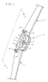
- An orthotic fulcrum 10 includes an elongated, rigid, thin, flat lower bar 11 and an elongated, rigid, thin, flat upper bar 12.
- the bars are also called arms in the art. These arms, which should be of equal thickness, lie in the same plane and engage each other adjacently by means of gear teeth on each of their ends at 12a (see FIG. 3) in the polycentric orthotic fulcrum design.
- the polycentric orthotic fulcrum is known in the art.
- the arms are connected by rigid, inner plate 13 on the inside of the orthotic fulcrum and rigid, outer plate 14 on the outside of the orthotic fulcrum point so as to overlap the arms' engaged gear teeth.
- the arms and plates are fastened together by screws 15 and 16. These screws pass through fulcrum point bushings 17 and 18 and fit into threaded holes in inner plate 13.
- the orthotic fulcrum bushings 17 and 18 serve as pivot points for the orthotic fulcrum assembly.
- the length of hinge bushings 17 and 18 should be slightly shorter than the combined thickness of either arm plus the outer plate 14, since such design permits locking of the orthotic fulcrum in any position to facilitate manufacture, assembly, and fitting into a larger assembly, such as an orthosis.
- the screws 15 and 16 are adjusted so as to permit the fulcrum point 10 to move freely over its range of motion, and then lock screw 19, which is positioned to simultaneously clamp a shoulder on each of screws 15 and 16, is tightened into a threaded hole in outer plate 14 so as to prevent screws 15 and 16 from turning.
- Stops are provided on the geared ends of arms 11 and 12 so as to limit their range of motion.
- a deceleration means is provided, which is the principle improvement in the art, as described below.
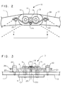
- Post 20 passes through friction reduction roller 21 and into a variably placed threaded hole in upper arm 12, to which it is tightened and adjusted so as to allow the roller 21 to turn freely.
- Post 22 passes through friction reduction roller 23 and into a variably placed hole in lower arm 11, to which it is tightened and adjusted so as to allow the roller 23 to turn freely.
- Pivot screw 24 passes through friction reduction roller 25 and is tightened into a threaded hole in outer plate 14, which hole is centered between assembled screws 15 and 16 on a line tangential to the adjacent pitch diameters of the gears on the ends of the assembled arms 11 and 12.
- a spring steel wire is formed serpentinely to make spring rod 26, which is assembled to fit around pivot screw 24 and roller 25.
- a shoulder on pivot screw 24 acts as a retainer to hold spring rod 26 against outer plate 14 and against the edges of screws 15 and 16.
- Spring rod 26 is curved to fit around screws 15 and 16 and is curved conversely to fit around friction reduction roller posts 20 and 22, the ends of spring rod 26 contact rollers 21 and 23 during extension of the orthotic fulcrum, resulting in deceleration of the angular velocity of the orthotic fulcrum and parts.
- the material and cross-sectional area of spring rod 26 can be varied to suit differences in user's activity level and state of health and to suit required rates of deceleration of the angular motion of the hinge.
- the angle of curvature of spring rod 26 can be varied to adjust the point when deceleration occurs, which is a function of when rollers 21 and 23 first contact spring rod 26 during orthotic extension.
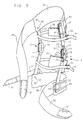
- Upright arms 12 are attached to each other by means of a thin metal band 27, varying in thickness, width and length, each determined by requirements of individual appendage size, usually one-half the circumference of the appendage at the same length proximal to the fulcrum point.
- the fastening means is rivets 40 drilled and pinned through both arm 12 and band 27.
- Band 28 is fastened to medial and lateral lower arms 11 in the same method as band 27 is fastened to the upper arms. Together with the arms 11 and 12, bands 27 and 28 make up the skeletal structure of the orthosis.
- Proximal circumference strap 29 encapsulates the appendage to the orthosis along with the distal circumference strap 30. These straps are compressive and hold the appendage firmly inside the orthosis. This is achieved by fastening strap 29 to band 27 at one end by permanent fixation to interface or pad 39 and removable fastener 31 to fixed fastener 32 at the other end for circumferential wrap. The same arrangement is used for the attachment of strap 30
- patella straps 33 and 36 Two more prehension straps are used to encapsulate the appendage, and they are the patella straps 33 and 36.
- Strap 33 is attached to pad 39 and arm 12 by nylon thread on one end and to truss clip 34 on the other. Truss clip 34 is attached to member 35 with nylon thread in a reinforce stitch pattern, completing the encapsulation of the knee, and also providing suspension.
- Member 35 is a pelite thermo pad that acts as an attachment point for patella straps 33 and 36. Strap 36 attaches to pad 38 in the same way patella strap 33 attaches to pad 39.
- Strap 37 is an anti-rotation strap and runs up through the orthosis and around the medial or lateral or both sides of the knee in a spiraling wrap attaching the band 27 with the origin of the band 28. This resists rotary forces at the fulcrum point of the orthosis when applied to a flexing and extending appendage.
Landscapes
- Health & Medical Sciences (AREA)
- Nursing (AREA)
- Orthopedic Medicine & Surgery (AREA)
- Engineering & Computer Science (AREA)
- Biomedical Technology (AREA)
- Heart & Thoracic Surgery (AREA)
- Vascular Medicine (AREA)
- Life Sciences & Earth Sciences (AREA)
- Animal Behavior & Ethology (AREA)
- General Health & Medical Sciences (AREA)
- Public Health (AREA)
- Veterinary Medicine (AREA)
- Orthopedics, Nursing, And Contraception (AREA)
- Soil Working Implements (AREA)
- Optical Fibers, Optical Fiber Cores, And Optical Fiber Bundles (AREA)
- Door And Window Frames Mounted To Openings (AREA)
Claims (10)
- Orthotisches Gerät zur Vorsehung von Verlängerungsstabilität und zur Begrenzung von Überdehnung, während Beugungsbeweglichkeit vorgesehen wird, wobei das Gerät folgendes einschließt:a. eine Anordnung von langgestreckten ersten und zweiten Armen (11,12);b. ein Mittel (29,30,37,38,39), um die Arme an dem Körper eines Benutzers auf entgegengesetzten Seiten eines Gelenks zu befestigen, das von dem Gerät geschützt werden soll;c. ein Verbindungsmittel (13,14,15,16) an den passenden Enden der Arme, das die Arme für relative Winkelbewegung miteinander verbindet, welche auf eine Ebene begrenzt wird, die den Armen gemeinsam ist; und dadurch gekennzeichnet, daß es weiterhin folgendes einschließt:d. ein Mittel zum Verringern der relativen Bewegungsrate zwischen den Armen über nur dem Teil der relativen Bewegung der Arme, das mit der maximalen Winkelverschiebung zwischen den Armen aufhört, wobei das Verlangsamungsmittel folgendes einschließt: ein langgestrecktes, Energie absorbierendes Glied (26), das eine reaktive Kraft erzeugen kann, die der Verschiebung eines Endes des Gliedes relativ zum anderen proportional ist, ein Mittel (19,24), an einer Stelle zwischen den passenden Enden des langgestreckten Gliedes, um das Glied gegen Bewegung relativ zu dem Verbindungsmittel zu befestigen, und erste und zweite Anschlagmittel (20,22), die derart auf den ersten und zweiten Armen angeordnet sind, so daß in sie von entgegengesetzten Enden des langgestreckten Gliedes nur zu bestimmten Zeitpunkten eingegriffen werden können, wobei das Anschlagmittel relativ angeordnet ist, und das langgestreckte Glied umrissen ist, daß in beide Anschlagmittel nur dann von dem langgestreckten Glied eingegriffen werden kann, wenn der relative Winkel zwischen den Armen sich einem Maximum nähert, wobei: (a) das Verlangsamungsmittel untätig bleibt und die Arme sich winklig relativ frei zueinander bewegen können, so lange wie die relative Winkelverschiebung der Arme klein genug bleibt, so daß das langgestreckte Glied nicht gleichzeitig in beide Anschlagmittel eingreift, aber (b) in beide Anschlagmittel eingegriffen wird und die relative Winkelbewegungsrate zwischen den Armen erhöhend verringert wird, während die Winkelverschiebung zwischen den Armen danach erhöht wird.
- Orthotisches Gerät nach Anspruch 1, in dema. das Verbindungsmittel ineinandergreifende Zahnrädermittel auf den passenden Enden der Arme einschließt, erste und zweite Verbindungsglieder (13,14), die so auf entgegengesetzten Seiten der Anordnung der Arme angeordnet sind, um relative seitliche Bewegung der Arme zu verhindern, und Glieder (15,16), die sich durch die Verbindungsglieder in der Nähe der passenden Enden der Arme erstrecken und sie umfassen, um die Glieder und die Arme zusammenzukoppeln, und um Wellen vorzusehen, um die sich die Arme drehen können; undb. das Verlangsamungsmittel auch ein Mittel (19,24) einschließt, das das langgestreckte Glied ungefähr an seinem Mittelpunkt und wie oben erwähnt an einem der Verbindungsglieder befestigt.
- Orthotisches Gerät nach Anspruch 2, in dema. das Verbindungsglied ein erstes Glied (19) mit einem Kopf umfasst, das einen Kopf hat, der in die die Wellen vorsehenden Glieder eingreifen kann, um Drehung der die Wellen vorsehenden Glieder zu verhindern;b. das langgestreckte Glied (26) entgegen dem einen Verbindungsglied (14) durch das Glied mit einem Kopf eingefangen ist; undc. das Mittel zur Befestigung des langgestreckten Gliedes an dem einen Verbindungsglied (14) ein zweites Glied (24) mit einem Kopf umfasst, welches das langgestreckte Glied auch gegen das eine Verbindungsmittel einschränkt, wobei das zweite Glied mit einem Kopf so auf der entgegengesetzten Seite des langgestreckten Gliedes von dem ersten Glied mit einem Kopf angeordnet ist, um das langgestreckte Glied gegen das erste Glied mit Kopf einem einzufangen.
- Orthotisches Gerät nach Anspruch 2, das Buchsen (17,18) einschließt, die von der einen Verbindungsplatte getragen werden, und in die von dem langgestreckten Glied eingegriffen werden kann, um den Widerstand gegen die relative Winkelbewegung der Arme, die von dem langgestreckten Glied aufgebracht wird, zu erhöhen.
- Orthotisches Gerät nach Anspruch 4, in dem die die Wellen vorsehenden Glieder (15,16) sich durch die Buchsen erstrecken und die Buchsen an dem einen Verbindungsglied befestigen.
- Orthotisches Gerät nach Anspruch 3, in dem die die Wellen vorsehenden Glieder in das zweite Verbindungsglied (13) eingeschraubt sind, wobei die Verbindungsglieder, wenn die Glieder gegen Drehung gesperrt sind, sich zu einem Ausmaß auseinander bewegen können, das ausreicht, um zu verhindern, daß die Glieder die relative Drehung der Arme reibend einschränkt.
- Orthotisches Gerät nach Anspruch 3, in dema. ein erstes Glied mit Gewinde entlang einer Linie angeordnet ist, die sich zwischen den Verlängerungsachsen der die Wellen vorsehenden Glieder und ungefähr in der Mitte zwischen den Achsen erstreckt; undb. ein zweites Glied mit Gewinde entlang einer zweiten Linie angeordnet ist, die sich normal zur erstgenannten Linie erstreckt und durch die Verlängerungsachse des ersten Gliedes mit einem Kopf geht.
- Orthotisches Gerät nach Anspruch 2, in dema. die passenden Endteile der Arme parallele Seiten und gleiche Dicke haben; undb. die Verbindungsglieder (13,14) flache Platte sind.
- Orthotisches Gerät nach einem der vorhergehenden Ansprüche 1-8, in dem das langgestreckte Glied (26) aus einem elastisch verformbaren Material hergestellt ist und einen schlangenförmigen Aufbau hat.
- Orthotisches Gerät nach einem der vorhergehenden Ansprüche 1-8, in dema. die Endteile des langgestreckten Gliedes um die Anschlagmittel (20,22) gerichtet sind, wenn sie wie oben in die Anschlagmittel eingreifen; undb. die Anschlagmittel Rollen (21,23) umfassen, in die so von dem langgestreckten Glied eingegriffen werden kann, um Reibung zwischen dem langgestreckten Glied und den Anschlagmitteln minimal zu halten, und dabei Beugungsbeweglichkeit in dem Gerät vorzusehen.
Applications Claiming Priority (3)
| Application Number | Priority Date | Filing Date | Title |
|---|---|---|---|
| US260943 | 1988-10-21 | ||
| US07/260,943 US4865024A (en) | 1988-10-21 | 1988-10-21 | Extension deceleration orthosis |
| PCT/US1989/004770 WO1990004371A1 (en) | 1988-10-21 | 1989-10-20 | Extension deceleration orthosis |
Publications (3)
| Publication Number | Publication Date |
|---|---|
| EP0439552A1 EP0439552A1 (de) | 1991-08-07 |
| EP0439552A4 EP0439552A4 (en) | 1991-11-21 |
| EP0439552B1 true EP0439552B1 (de) | 1995-03-29 |
Family
ID=22991296
Family Applications (1)
| Application Number | Title | Priority Date | Filing Date |
|---|---|---|---|
| EP89913140A Expired - Lifetime EP0439552B1 (de) | 1988-10-21 | 1989-10-20 | Orthose der geschwindigkeitsabnahme durch verlaengerung |
Country Status (7)
| Country | Link |
|---|---|
| US (1) | US4865024A (de) |
| EP (1) | EP0439552B1 (de) |
| JP (1) | JPH0813307B2 (de) |
| AT (1) | ATE120357T1 (de) |
| CA (1) | CA1319870C (de) |
| DE (1) | DE68921986D1 (de) |
| WO (1) | WO1990004371A1 (de) |
Cited By (2)
| Publication number | Priority date | Publication date | Assignee | Title |
|---|---|---|---|---|
| US9737431B1 (en) | 2013-09-27 | 2017-08-22 | Weber Orthopedic, Inc. | Wrist-forearm-elbow anti-rotation orthosis |
| US9782285B1 (en) | 2013-09-27 | 2017-10-10 | Weber Orthopedic, Inc. | Elbow-forearm anti-rotation orthosis |
Families Citing this family (93)
| Publication number | Priority date | Publication date | Assignee | Title |
|---|---|---|---|---|
| US5658241A (en) * | 1990-02-09 | 1997-08-19 | Ultraflex Systems, Inc. | Multi-functional dynamic splint |
| US5749840A (en) * | 1989-12-07 | 1998-05-12 | Ultraflex Systems, Inc. | Dynamic splint |
| US5358469A (en) * | 1990-02-09 | 1994-10-25 | Ultraflex Systems, Inc. | Dynamic splint |
| US5036837A (en) * | 1990-02-09 | 1991-08-06 | Bio-Tec, Inc. | Dynamic extension splint |
| US5022390A (en) * | 1990-05-11 | 1991-06-11 | Whiteside Stacey A | Orthotic device for limiting limb notion at a joint |
| US5167612A (en) * | 1990-07-30 | 1992-12-01 | Bonutti Peter M | Adjustable orthosis |
| US5571078A (en) * | 1993-06-30 | 1996-11-05 | Empi, Inc. | Range-of-motion ankle splint |
| US5437619A (en) * | 1993-06-30 | 1995-08-01 | Empi, Inc. | Range-of-motion splint with eccentric spring |
| US5520627A (en) * | 1993-06-30 | 1996-05-28 | Empi, Inc. | Range-of-motion ankle splint |
| US5399154A (en) * | 1993-06-30 | 1995-03-21 | Empi, Inc. | Constant torque range-of-motion splint |
| US5437611A (en) * | 1993-12-01 | 1995-08-01 | Orthotic Rehabilitation Products, Inc. | Dynamic brace joint |
| CA2186227C (en) * | 1994-03-22 | 1999-09-28 | Mark Deharde | Multi-functional dynamic splint |
| DE4418382A1 (de) * | 1994-05-26 | 1995-11-30 | Michael Klopf | Orthese |
| US5575764A (en) * | 1994-12-14 | 1996-11-19 | Van Dyne; Leonard A. | Prosthetic joint with dynamic torque compensator |
| US5891061A (en) * | 1997-02-20 | 1999-04-06 | Jace Systems, Inc. | Brace for applying a dynamic force to a jointed limb |
| US6206846B1 (en) * | 1997-03-28 | 2001-03-27 | John P. Kenney | Orthotic device for treating contractures due to immobility |
| US5891068A (en) * | 1997-03-28 | 1999-04-06 | Kenney; John P. | Orthotic device for treating contractures due to immobility |
| US6064912A (en) * | 1997-03-28 | 2000-05-16 | Kenney; John P. | Orthotic/electrotherapy for treating contractures due to immobility |
| US6010474A (en) * | 1997-06-06 | 2000-01-04 | Wycoki; Michael | Orthopedic brace for legs |
| US6074355A (en) * | 1998-02-06 | 2000-06-13 | Bartlett; Edwin Clary | Knee brace |
| US6113562A (en) | 1998-06-01 | 2000-09-05 | Peter M. Bonutti | Shoulder orthosis |
| AU4167599A (en) * | 1998-06-19 | 2000-01-05 | Tamotsu Sakima | Knee outfit and joint supporting member |
| DE29822445U1 (de) * | 1998-12-17 | 1999-02-25 | IPOS Gesellschaft für integrierte Prothesen-Entwicklung und orthopädietechnischen Service mbH & Co KG, 21337 Lüneburg | Knieorthese |
| US6039707A (en) * | 1999-02-16 | 2000-03-21 | Crawford; Michael K. | Pelvic support and walking assistance device |
| DE59912937D1 (de) * | 1999-12-29 | 2006-01-19 | Roland Peter Jakob | Vorrichtung zur Ausübung einer statischen oder dynamischen vorderen, resp. hinteren Translationskraft am Kniegelenk |
| US6589195B1 (en) * | 2000-05-26 | 2003-07-08 | Orthomerica Products, Inc. | Modular adjustable prophylactic hip orthosis and adduction/abduction joint |
| US6502577B1 (en) | 2000-09-18 | 2003-01-07 | Peter M. Bonutti | Method for moving finger joints |
| US6503213B2 (en) | 2000-12-01 | 2003-01-07 | Peter M. Bonutti | Method of using a neck brace |
| US6575926B2 (en) | 2000-12-15 | 2003-06-10 | Bonutti 2003 Trust-A | Myofascial strap |
| US6752774B2 (en) * | 2001-06-08 | 2004-06-22 | Townsend Design | Tension assisted ankle joint and orthotic limb braces incorporating same |
| US7048704B2 (en) * | 2001-09-28 | 2006-05-23 | Sieller Richard T | Orthotic device |
| US7488300B2 (en) | 2002-02-15 | 2009-02-10 | Thusane | Bicentric hinge for use in a brace |
| US6969363B2 (en) * | 2002-02-15 | 2005-11-29 | Thuasne | Bicentric hinge for use in a brace |
| WO2003090651A1 (en) * | 2002-04-25 | 2003-11-06 | Ultraflex Systems, Inc. | Ambulating knee joint |
| US8100844B2 (en) * | 2002-04-25 | 2012-01-24 | Ultraflex Systems, Inc. | Ambulating ankle and knee joints with bidirectional dampening and assistance using elastomeric restraint |
| US7314490B2 (en) | 2002-08-22 | 2008-01-01 | Victhom Human Bionics Inc. | Actuated leg prosthesis for above-knee amputees |
| US7736394B2 (en) | 2002-08-22 | 2010-06-15 | Victhom Human Bionics Inc. | Actuated prosthesis for amputees |
| EP1547568B1 (de) * | 2002-08-30 | 2013-01-02 | Honda Giken Kogyo Kabushiki Kaisha | Geschwindigkeitsreduzierer für eine gehhilfe |
| US7192407B2 (en) * | 2003-01-30 | 2007-03-20 | Djo, Llc | Motion controlling hinge for orthopedic brace |
| US7150721B2 (en) * | 2003-06-30 | 2006-12-19 | Thuasne | Knee brace with dynamic counterforce |
| US20050107889A1 (en) | 2003-11-18 | 2005-05-19 | Stephane Bedard | Instrumented prosthetic foot |
| US7815689B2 (en) | 2003-11-18 | 2010-10-19 | Victhom Human Bionics Inc. | Instrumented prosthetic foot |
| CA2550027A1 (en) * | 2004-01-07 | 2005-07-28 | Dj Orthopedics, Llc | Knee brace hinges with adaptive motion |
| DE602005023580D1 (de) * | 2004-01-07 | 2010-10-28 | Djo Llc | Kniestützscharniere mit doppelten drehachsen |
| US7637959B2 (en) | 2004-02-12 | 2009-12-29 | össur hf | Systems and methods for adjusting the angle of a prosthetic ankle based on a measured surface angle |
| US8066656B2 (en) | 2005-10-28 | 2011-11-29 | Bonutti Research, Inc. | Range of motion device |
| US7452342B2 (en) | 2004-03-08 | 2008-11-18 | Bonutti Research Inc. | Range of motion device |
| US20050273025A1 (en) * | 2004-05-19 | 2005-12-08 | Houser Guy M | Braces having an assembly for exerting a manually adjustable force on a limb of a user |
| US7811242B2 (en) * | 2004-06-24 | 2010-10-12 | Djo, Llc | Motion controlling hinge for orthopedic brace |
| CA2592042C (en) | 2004-12-22 | 2014-12-16 | Oessur Hf | Systems and methods for processing limb motion |
| US20060142680A1 (en) * | 2004-12-29 | 2006-06-29 | Iarocci Michael A | Active assist for the ankle, knee and other human joints |
| US8801802B2 (en) | 2005-02-16 | 2014-08-12 | össur hf | System and method for data communication with a mechatronic device |
| SE528516C2 (sv) | 2005-04-19 | 2006-12-05 | Lisa Gramnaes | Kombinerat aktivt och passivt benprotessystem samt en metod för att utföra en rörelsecykel med ett sådant system |
| US8012108B2 (en) | 2005-08-12 | 2011-09-06 | Bonutti Research, Inc. | Range of motion system and method |
| WO2007027808A2 (en) | 2005-09-01 | 2007-03-08 | össur hf | System and method for determining terrain transitions |
| JP4550137B2 (ja) * | 2006-03-20 | 2010-09-22 | 英一 元田 | 荷重ブレーキ付き長下肢装具 |
| RU2309708C1 (ru) * | 2006-03-20 | 2007-11-10 | Государственное образовательное учреждение высшего профессионального образования Марийский государственный технический университет | Ортопедический аппарат для коленного сустава |
| US7544174B2 (en) * | 2006-09-29 | 2009-06-09 | Djo, Llc | Quiet flexion/extension stop for orthopedic brace and orthopedic brace incorporating a quiet flexion/extension stop |
| EP2104476B1 (de) | 2007-01-05 | 2016-01-06 | Victhom Human Bionics Inc. | Aktivmechanismus mit hohem drehmoment für orthosenvorrichtungen |
| WO2008080231A1 (en) * | 2007-01-05 | 2008-07-10 | Victhom Human Bionics Inc. | Joint actuation mechanism for a prosthetic and/or orthotic device having a compliant transmission |
| US8920346B2 (en) | 2007-02-05 | 2014-12-30 | Bonutti Research Inc. | Knee orthosis |
| US7553289B2 (en) * | 2007-02-20 | 2009-06-30 | Gregory Cadichon | Method, apparatus, and system for bracing a knee |
| US20110098618A1 (en) * | 2007-05-03 | 2011-04-28 | Darren Fleming | Cable Knee Brace System |
| WO2009015364A1 (en) | 2007-07-25 | 2009-01-29 | Bonutti Research Inc. | Orthosis apparatus and method of using an orthosis apparatus |
| JP2009090042A (ja) * | 2007-10-12 | 2009-04-30 | Honda Motor Co Ltd | 歩行補助装置 |
| US8905950B2 (en) | 2008-03-04 | 2014-12-09 | Bonutti Research, Inc. | Shoulder ROM orthosis |
| CN102036626B (zh) | 2008-03-24 | 2014-07-02 | 奥瑟Hf公司 | 经股的假肢系统和用于操作该系统的方法 |
| US7963933B2 (en) * | 2008-04-09 | 2011-06-21 | Nace Richard A | Osteoarthritis knee orthosis |
| US9089403B2 (en) * | 2009-05-20 | 2015-07-28 | Medical Alliance Sa | Knee orthosis with hinged shin and thigh cuffs |
| US10085869B2 (en) * | 2008-05-20 | 2018-10-02 | Medical Alliance, S.A. | Knee orthosis for treatment of PCL injury |
| US8308669B2 (en) * | 2008-05-20 | 2012-11-13 | Nace Richard A | Knee orthosis with hinged shin and thigh cuff |
| US8308671B2 (en) * | 2008-08-28 | 2012-11-13 | Nace Richard A | Knee orthosis |
| WO2010087602A2 (ko) * | 2009-02-02 | 2010-08-05 | Cho Kyung Il | 발목보호대와 탈, 부착 가능한 무릎보호대 |
| US9289640B2 (en) | 2009-03-23 | 2016-03-22 | Steven M. Cersonsky | Resistance brace |
| US20110065553A1 (en) * | 2009-03-23 | 2011-03-17 | Cersonsky Steven M | Body Mounted Muscular Brace |
| EP2598087B1 (de) * | 2010-07-28 | 2015-03-25 | Indaco S.r.l. | Stütze für menschliche gelenke |
| WO2012037275A1 (en) | 2010-09-16 | 2012-03-22 | Steadman Philippon Research Institute | Posterior cruciate ligament support brace |
| US8882688B1 (en) | 2010-11-15 | 2014-11-11 | Craig Ancinec | Orthotic joint stabilizing assembly |
| EP2773301B1 (de) | 2011-10-31 | 2016-03-16 | Ossur Hf | Orthopädische vorrichtung zur dynamischen behandlung des knies |
| US9351864B2 (en) | 2013-01-25 | 2016-05-31 | Ossur Hf | Orthopedic device having a dynamic control system |
| US9539135B2 (en) | 2013-01-25 | 2017-01-10 | Ossur Hf | Orthopedic device having a dynamic control system and method for using the same |
| US10413437B2 (en) | 2013-01-25 | 2019-09-17 | Ossur Iceland Ehf | Orthopedic device having a dynamic control system and method for using the same |
| US9402759B2 (en) | 2013-02-05 | 2016-08-02 | Bonutti Research, Inc. | Cervical traction systems and method |
| US9561118B2 (en) | 2013-02-26 | 2017-02-07 | össur hf | Prosthetic foot with enhanced stability and elastic energy return |
| EP3010456B1 (de) | 2013-06-21 | 2020-05-27 | Ossur Iceland EHF | Dynamisches spannungssystem für orthopädische vorrichtung |
| US9597786B2 (en) | 2013-08-22 | 2017-03-21 | Ossur Hf | Torque limiting tool and method for using the same |
| EP3128958B1 (de) | 2014-04-11 | 2019-08-07 | Össur HF | Fussprothese mit abnehmbaren flexiblen elementen |
| US10512305B2 (en) | 2014-07-11 | 2019-12-24 | Ossur Hf | Tightening system with a tension control mechanism |
| WO2016069839A1 (en) | 2014-10-31 | 2016-05-06 | Ossur Hf | Orthopedic device having a dynamic control system |
| US11547590B2 (en) | 2017-11-27 | 2023-01-10 | Ossur Iceland Ehf | Orthopedic device having a suspension element |
| CN109172286B (zh) * | 2018-07-25 | 2020-10-02 | 福州大学 | 一种下肢康复助行装置及其工作方法 |
| DE102020001327A1 (de) * | 2020-02-28 | 2021-09-02 | Bernhard Sacherer | Orthesengelenk zum Bilden einer Funktionsstellung mit gefederter Auslenkung. |
| JP7718783B2 (ja) * | 2021-11-10 | 2025-08-05 | 株式会社キトー | 膝装着具 |
Family Cites Families (13)
| Publication number | Priority date | Publication date | Assignee | Title |
|---|---|---|---|---|
| GB813501A (en) * | 1954-09-25 | 1959-05-21 | William Louis Cresswell | Improvements in or relating to apparatus for use by disabled persons |
| US817785A (en) * | 1906-02-23 | 1906-04-17 | Charles E Kritsch | Joint for artificial limbs. |
| US1072369A (en) * | 1913-04-26 | 1913-09-02 | Edward Spahn | Knee and ankle brace. |
| DE3040595C1 (de) * | 1980-10-29 | 1982-01-21 | Harald 2359 Henstedt-Ulzburg Lodenkämper | Stabilisierungsbandage fuer das Kniegelenk |
| US4370977A (en) * | 1981-05-04 | 1983-02-01 | Kenneth D. Driver | Knee and elbow brace |
| GB2098490A (en) * | 1981-05-19 | 1982-11-24 | Gavan John | Body support |
| US4524764A (en) * | 1983-09-06 | 1985-06-25 | Miller Harold E | Knee brace |
| DE3344422A1 (de) * | 1983-12-08 | 1985-06-20 | S + G Implants GmbH, 2400 Lübeck | Orthese fuer kniegelenke |
| FR2559394B1 (fr) * | 1984-02-10 | 1986-07-11 | Carsalade Charles | Appareil pour faciliter la pratique du ski alpin notamment |
| US4829989A (en) * | 1985-06-17 | 1989-05-16 | Deamer Richard M | Stoop laborer's body support having hinge with adjustable spring biasing |
| US4803975A (en) * | 1987-03-31 | 1989-02-14 | Meyers Andrew H | Orthotic device for controlling knee instabilities |
| US4751920A (en) * | 1987-01-20 | 1988-06-21 | 3D Orthopedic, Inc. | Pivoting knee brace with rotating and translating tibia collar |
| US4961416A (en) * | 1989-06-12 | 1990-10-09 | Orthopedic Systems, Inc. | Knee brace |
-
1988
- 1988-10-21 US US07/260,943 patent/US4865024A/en not_active Ceased
-
1989
- 1989-09-25 CA CA000612888A patent/CA1319870C/en not_active Expired - Fee Related
- 1989-10-20 WO PCT/US1989/004770 patent/WO1990004371A1/en not_active Ceased
- 1989-10-20 JP JP2500080A patent/JPH0813307B2/ja not_active Expired - Lifetime
- 1989-10-20 AT AT89913140T patent/ATE120357T1/de not_active IP Right Cessation
- 1989-10-20 EP EP89913140A patent/EP0439552B1/de not_active Expired - Lifetime
- 1989-10-20 DE DE68921986T patent/DE68921986D1/de not_active Expired - Lifetime
Cited By (2)
| Publication number | Priority date | Publication date | Assignee | Title |
|---|---|---|---|---|
| US9737431B1 (en) | 2013-09-27 | 2017-08-22 | Weber Orthopedic, Inc. | Wrist-forearm-elbow anti-rotation orthosis |
| US9782285B1 (en) | 2013-09-27 | 2017-10-10 | Weber Orthopedic, Inc. | Elbow-forearm anti-rotation orthosis |
Also Published As
| Publication number | Publication date |
|---|---|
| EP0439552A1 (de) | 1991-08-07 |
| JPH04501227A (ja) | 1992-03-05 |
| CA1319870C (en) | 1993-07-06 |
| JPH0813307B2 (ja) | 1996-02-14 |
| ATE120357T1 (de) | 1995-04-15 |
| WO1990004371A1 (en) | 1990-05-03 |
| US4865024A (en) | 1989-09-12 |
| DE68921986D1 (de) | 1995-05-04 |
| EP0439552A4 (en) | 1991-11-21 |
Similar Documents
| Publication | Publication Date | Title |
|---|---|---|
| EP0439552B1 (de) | Orthose der geschwindigkeitsabnahme durch verlaengerung | |
| USRE37209E1 (en) | Extension deceleration orthosis | |
| US4508111A (en) | Adjustable splint | |
| US4657000A (en) | Adjustable splint and securing means therefor | |
| US4433679A (en) | Knee and elbow brace | |
| CA1185136A (en) | Adjustable splint | |
| US4370977A (en) | Knee and elbow brace | |
| CA2066151C (en) | Orthosis with joint distraction | |
| US5358469A (en) | Dynamic splint | |
| US5857989A (en) | Dynamic orthopedic knee brace assembly | |
| CA1314779C (en) | Cuff device | |
| US4538600A (en) | Adjustable splint | |
| US4751920A (en) | Pivoting knee brace with rotating and translating tibia collar | |
| US5658241A (en) | Multi-functional dynamic splint | |
| AU559360B2 (en) | Adjustable splint | |
| JPH02502258A (ja) | 自動調整カフ装置 | |
| US20040267179A1 (en) | Knee unloading orthotic device and method | |
| US7850632B2 (en) | Knee brace having an adaptable thigh pad | |
| EP1861051B1 (de) | Verstellbare knieschiene | |
| CN215228891U (zh) | 为身体关节提供主动协助的装置 | |
| JPS62102756A (ja) | 膝関節軟性回旋装具 | |
| EP4464286A1 (de) | Orthese | |
| US20050148914A1 (en) | Adjustable range of motion limiter | |
| CA2263040C (en) | Multi-functional dynamic splint |
Legal Events
| Date | Code | Title | Description |
|---|---|---|---|
| PUAI | Public reference made under article 153(3) epc to a published international application that has entered the european phase |
Free format text: ORIGINAL CODE: 0009012 |
|
| 17P | Request for examination filed |
Effective date: 19910422 |
|
| AK | Designated contracting states |
Kind code of ref document: A1 Designated state(s): AT BE CH DE FR GB IT LI LU NL SE |
|
| A4 | Supplementary search report drawn up and despatched |
Effective date: 19911001 |
|
| AK | Designated contracting states |
Kind code of ref document: A4 Designated state(s): AT BE CH DE FR GB IT LI LU NL SE |
|
| 17Q | First examination report despatched |
Effective date: 19940225 |
|
| GRAA | (expected) grant |
Free format text: ORIGINAL CODE: 0009210 |
|
| AK | Designated contracting states |
Kind code of ref document: B1 Designated state(s): AT BE CH DE FR GB IT LI LU NL SE |
|
| PG25 | Lapsed in a contracting state [announced via postgrant information from national office to epo] |
Ref country code: IT Free format text: LAPSE BECAUSE OF FAILURE TO SUBMIT A TRANSLATION OF THE DESCRIPTION OR TO PAY THE FEE WITHIN THE PRE;WARNING: LAPSES OF ITALIAN PATENTS WITH EFFECTIVE DATE BEFORE 2007 MAY HAVE OCCURRED AT ANY TIME BEFORE 2007. THE CORRECT EFFECTIVE DATE MAY BE DIFFERENT FROM THE ONE RECORDED.SCRIBED TIME-LIMIT Effective date: 19950329 Ref country code: BE Effective date: 19950329 Ref country code: FR Effective date: 19950329 Ref country code: NL Free format text: LAPSE BECAUSE OF NON-PAYMENT OF DUE FEES Effective date: 19950329 Ref country code: AT Effective date: 19950329 Ref country code: CH Effective date: 19950329 Ref country code: LI Effective date: 19950329 |
|
| REF | Corresponds to: |
Ref document number: 120357 Country of ref document: AT Date of ref document: 19950415 Kind code of ref document: T |
|
| REF | Corresponds to: |
Ref document number: 68921986 Country of ref document: DE Date of ref document: 19950504 |
|
| PG25 | Lapsed in a contracting state [announced via postgrant information from national office to epo] |
Ref country code: SE Effective date: 19950629 |
|
| PG25 | Lapsed in a contracting state [announced via postgrant information from national office to epo] |
Ref country code: DE Effective date: 19950630 |
|
| REG | Reference to a national code |
Ref country code: CH Ref legal event code: PL |
|
| EN | Fr: translation not filed | ||
| NLV1 | Nl: lapsed or annulled due to failure to fulfill the requirements of art. 29p and 29m of the patents act | ||
| PG25 | Lapsed in a contracting state [announced via postgrant information from national office to epo] |
Ref country code: GB Effective date: 19951020 |
|
| PG25 | Lapsed in a contracting state [announced via postgrant information from national office to epo] |
Ref country code: LU Free format text: LAPSE BECAUSE OF NON-PAYMENT OF DUE FEES Effective date: 19951031 |
|
| PLBE | No opposition filed within time limit |
Free format text: ORIGINAL CODE: 0009261 |
|
| STAA | Information on the status of an ep patent application or granted ep patent |
Free format text: STATUS: NO OPPOSITION FILED WITHIN TIME LIMIT |
|
| 26N | No opposition filed | ||
| GBPC | Gb: european patent ceased through non-payment of renewal fee |
Effective date: 19951020 |