EP0439496B1 - A film system for a cine camera - Google Patents
A film system for a cine camera Download PDFInfo
- Publication number
- EP0439496B1 EP0439496B1 EP89911767A EP89911767A EP0439496B1 EP 0439496 B1 EP0439496 B1 EP 0439496B1 EP 89911767 A EP89911767 A EP 89911767A EP 89911767 A EP89911767 A EP 89911767A EP 0439496 B1 EP0439496 B1 EP 0439496B1
- Authority
- EP
- European Patent Office
- Prior art keywords
- claw
- film
- gripper
- arm
- crank
- Prior art date
- Legal status (The legal status is an assumption and is not a legal conclusion. Google has not performed a legal analysis and makes no representation as to the accuracy of the status listed.)
- Expired - Lifetime
Links
Images


Classifications
-
- G—PHYSICS
- G03—PHOTOGRAPHY; CINEMATOGRAPHY; ANALOGOUS TECHNIQUES USING WAVES OTHER THAN OPTICAL WAVES; ELECTROGRAPHY; HOLOGRAPHY
- G03B—APPARATUS OR ARRANGEMENTS FOR TAKING PHOTOGRAPHS OR FOR PROJECTING OR VIEWING THEM; APPARATUS OR ARRANGEMENTS EMPLOYING ANALOGOUS TECHNIQUES USING WAVES OTHER THAN OPTICAL WAVES; ACCESSORIES THEREFOR
- G03B1/00—Film strip handling
- G03B1/18—Moving film strip by means which act on the film between the ends thereof
- G03B1/20—Acting means
- G03B1/22—Claws or pins engaging holes in the film
Definitions
- the invention relates to a film switching mechanism specified in the preamble of claim 1.
- a film switching mechanism in a motion picture film recording camera which the to be transported, perforated film at both edges is gradually moved past an exposure window with the aid of transport grippers which, together with the associated transport gear, are arranged on both sides and symmetrically to the central plane perpendicular to the film center.
- the transport grippers are moved by the respective associated transport gear so that the transport tip of the transport grippers runs through an elongated, self-contained curve which enters the film running surface at one end and leaves it again at the other end.
- each transport gear has two shafts, each of which is coupled to a crank.
- the end of one crank forms an articulation point at which the transport gripper tab is articulated.
- In the middle section of the transport gripper tab there is also an articulation point to which a link is articulated, which is connected to the end of the other crank.
- the two shafts connected to the cranks are connected to a main drive shaft via a rotating toothed pulley, the opposite transmission gears being driven by the same common drive shaft, which is supported in a bearing on both sides of the central plane.
- crank mechanism for a locking gripper is provided, which is connected to the shaft driving the end of the transport gripper tab.
- the angular offset between the two cranks on the common shaft is chosen so that the locking gripper is outside the film running surface as long as the transport gripper tips continue to move the film.
- a disadvantage of the known film switching mechanism is that in order to change the feed step and the angular relationships, that is to say the immersion depth and tip path of the transport gripper, considerable structural changes are required and that the stroke depth is relatively large, so that the film engages in the perforation holes by engaging the transport gripper tips an arc path is moved, which has a so-called "sawing effect" due to the sliding of the transport gripper tip in the film perforation.
- a gripper switching mechanism which consists of two cranks, of which the first crank acts on one end of a link with the gripper pins, while the second crank is connected to the other end of the link via an intermediate lever. Both cranks are coupled together by gears.
- this known gripper switch mechanism considerable structural changes are required to change the immersion depth and the movement path of the gripper tips, in order to achieve the smallest possible but sufficient immersion depth of the gripper tips depending on the local conditions.
- the object of the present invention is to improve a generic film switching device with regard to the adaptability to local conditions.
- the solution according to the invention creates a film switching mechanism that can be adapted to local conditions in a simple manner, so that with small changes, different step and pull angle ratios and a different stroke depth are possible, and easy balancing of the film switching mechanism is ensured, with a small space requirement in the area the film track is achieved.
- the film switching mechanism enables other step and angle ratios, e.g. 2-, 3-, 4-, 5- or 6-hole circuits as well as a single and double-sided drive, in which two film switching mechanisms engage in two rows of perforations in a film and transport the film.
- step and angle ratios e.g. 2-, 3-, 4-, 5- or 6-hole circuits as well as a single and double-sided drive, in which two film switching mechanisms engage in two rows of perforations in a film and transport the film.
- An advantageous embodiment of the solution according to the invention is characterized in that the control arm slides on a control cam with its end opposite the swivel joint.
- a further embodiment of the solution according to the invention is characterized in that the gripper lever is extended beyond the fixed bearing and carries at its end a pivot bearing which moves a locking gripper pin mounted perpendicular to the film running surface back and forth via a locking gripper lever and a further pivot bearing.
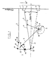
- FIGS. 1 to 3 show schematically or in a partially sectioned side view the structural design of the film switching mechanism according to the invention for a motion picture film recording camera for transporting a film 1.
- the film switching mechanism has an immersion gripper 2 which is provided at one end with gripper tips 21, 22 which engage in the perforation holes 10 of the film 1.
- the center section 20 of the diving gripper 2 has a gripper tab point 13 to which one end of a working arm 5 of a gripper crank is articulated, the other end of which is connected to a gripper crank joint 12.
- the gripper crank joint 12 is part of a working arm 8, which is connected together with a crank arm 4 to a rear derailleur axis 9.
- the drive shaft 11 is connected to a drive motor, not shown, via a coupling part.
- the crank arm 4 has a control crank joint 19 to which one end of a control arm 6 is articulated.
- the drive shaft 11, the crank arm 4 and the drive arm 8 are parts of a derailleur axis 9, which additionally has a balancing segment 40, with which dynamic balancing of the drive parts of the film derailleur is possible in a simple manner.
- the other end of the control arm 6 is connected via a swivel joint 15 to a swing arm 71, which is a lever a rocker 7 forms.
- the rocker 7 is mounted in a fixed bearing 14 and has a second lever in the form of a gripper lever 72 and an extension 73, the three levers 71, 72, 73 of the rocker 7 being in a fixed geometric association with one another.
- the end of the gripper lever 72 forms a gripper joint 16 to which the end 23 of the plunge gripper 2 opposite the gripper tips 21, 22 is articulated.
- the extension 73 is connected to a pivot bearing 17 on which a locking gripper lever 31 is articulated.
- the locking gripper lever 31 is connected via a pivot bearing 18 to a locking gripper tab 32 which is shrunk onto a locking gripper pin 3, the front, flattened tip of which engages in the perforation holes 10 of the film 1 to the image state.
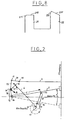
- Figure 2 illustrates the lever lengths and main dimensions of the film switching mechanism in a schematic sketch.
- the plunger grips an angle of approximately 21 ° around the center of the stroke during its back and forth movement.
- the control arm 6 executes a small stroke, while, for example, as a result of the leg length of the extension 73 of the rocker 7, a large stroke is carried out in the region of the pivot bearing 17, which causes the blocking gripper pin 3 to be immersed deeply into the perforation holes 10 of film 1 results.
- a major advantage of the solution according to the invention is that, on the one hand, by arranging a control arm 6, a small stroke of this control arm 6 is sufficient to cause a large stroke of the locking gripper pin 3 and, on the other hand, by slight changes in the dimensions of the individual film switching elements or by a displacement of the Pivot points to influence the immersion depth and stroke position.
- This simple influence on the stroke position and immersion depth of the tips of the locking gripper pin 3 and the diving gripper tips 21, 22 is particularly advantageous for the equipment of different film recording cameras, since the respective requirements can be taken into account with simple means.
- the film switching mechanism according to the invention can be easily converted to one, two, three, four or five-hole circuits without the need for a separate film switching mechanism.
- a straight or curved film path can be brought about by a corresponding immersion depth of the immersion gripper tips.
- a one- or two-sided arrangement of the film switching mechanism for one-sided or two-sided transport of a film is also possible.
- An essential advantage of the solution according to the invention is that sufficient space is created in the area of the film plane by a corresponding shift of the film switch parts from the film plane in order to be able to arrange additional elements of a film camera there.
- a uniform change in the stroke size H can be achieved by changing the length a of the drive arm 8.
- a one-sided change in the stroke size in the upper stroke range can be achieved by changing the dimension b of the gripper lever 72.
- a one-sided change in the stroke size in the lower region is achieved by changing the dimension c of the plunger gripper 2 between the gripper joint 16 and the gripper link point 13 and by shifting the center of the axis of the rocker 7 in the direction of the plunger gripper in accordance with the arrow A.
- a change in the stroke position is possible by changing the dimension d of the working arm 5.
- All articulation points 12 to 19 of the film switching mechanism can optionally consist of ball bearings or slide bearings, the former allowing maintenance-free operation of the film switching mechanism, while the latter ensure even smoother running, but require occasional maintenance, particularly in the case of film cameras with high transport speeds.
- roller bearings which are characterized on the one hand by the fact that they are maintenance-free and on the other hand have a smoother running than ball bearings.
- a suitable mounting of the articulation points can therefore be provided, with no design changes to the film switching mechanism being necessary.
- FIG. 3 shows the geometric configuration of the individual switching mechanism elements and in particular illustrates the structure of the switching mechanism axis 9, the rocker arm 7 and the plunger gripper 2.
- the rear derailleur axis 9 has the gripper crank joint 12 and the control crank joint 19, on which the working arm 5 and the control arm 6 are articulated.
- the rear derailleur axis 9 has a balancing segment 40, which is used for dynamic balancing of the film rear derailleur.
- the rocker 7 consists of an obtuse angle between the gripper lever 72 and the extension 73, on which the swing arm 71 is articulated in a fixed angular relationship to one another.
- the rocker arm 7 swings driven by the control arm 6 around the fixed bearing 14.
- the locking gripper pin 3 engages with its tip into a perforation hole 10 of the film 1 during the image stand and is disengaged from the perforation holes 10 of the film 1 during film transport. By rotating the locking gripper pin 3 by 180 °, the locking gripper pin 3 can be adjusted in a simple manner will.
- FIG. 4 shows a top view
- FIG. 5 shows a side view
- FIG. 6 shows a rear view of the rear derailleur axis 9.
- FIG. 7 schematically shows the transport gripper working curve in relation to the film plane 100 and illustrates the extremely small immersion depth of the diving gripper tips in the film perforations, so that on the one hand excessive stress on the film perforation is avoided and on the other hand the flat film web is not impaired.
- the degrees entered in the schematic representation of the plunger gripper working curve according to FIG. 3 relate to the angle of rotation of the crank arm 4, the start of the stroke being set at 0 ° or 360 °.
- the illustration according to FIG. 3 shows that the crank arm 4 has made an angle of rotation of 120 ° from the start of the stroke to the end of the stroke, this part of the curve of the engagement of the diving gripper tips in the film perforation being distinguished by a flat, uniform course.
- FIG. 8 illustrates in an enlarged representation the shape of the plunger gripper tips 21, 22, which are constructed in such a way that, on the one hand, a gentle intervention into the film perforation takes place through mutual contact of the plunger gripper tips with the respective perforation edges of the film and, on the other hand, the film during the lifting movement of the plunger gripper 2 can slide along the diving gripper tips 21, 22 and is therefore not forced to follow the slight lifting movement of the diving gripper 2.
- the immersion gripper tip 21 which is at the front in the transport direction of the film has a flattened end edge 210 which is chamfered at the front edge 211 in the transport direction of the film.
- the diving gripper tip 22 which is at the rear in the transport direction, on the other hand has an oblique end edge 220, which also is bevelled on the front edge 221 in the direction of transport of the film.
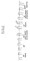
- FIG. 9 illustrates the individual movement phases of the diving gripper tips when engaging in the film perforation, with six lifting phases starting at 0 ° or 360 °, 30 °, 56 °, 83 °, 100 ° and 120 °.
- both immersion gripper tips 21, 22 perform the same load-bearing portion, since the front edges of both immersion gripper tips 21, 22 rest on the front edges of the successive perforation holes in the film perforation. The same applies to the center of the stroke, which is reached at around 56 °.
- Figure 9 illustrates that the special shape of the plunger tips in conjunction with a low immersion depth of the plunger tips in the film perforation ensures that the perforation holes slide along the plunger tips during the lifting movement, so that the film is essentially held in the film plane and no curve assumes.
- a curve control in particular a constant-thickness curve, can be used, which makes it possible to influence the movement of the diving gripper in order to influence the end points of the curve according to FIG.
- the immersion movement caused by the control arm can remain at the end points, so that almost any movement paths of the immersion gripper tips can be achieved.
- straight and circular film tracks are possible with the film switching mechanism according to the invention.
- Figure 10 shows a plan view of the tip of the locking gripper pin 3, the adjustment surfaces 35, 36 of which are offset from the center of the locking gripper pin 3 by a small amount, so that a different engagement point of the locking gripper pin 3 is achieved by rotating the locking gripper pin 3 by 180 °.
- the adjustment surfaces 35, 36 have a bevel, indicated by dashed lines, to facilitate the engagement of the locking gripper pin 3 in the Perforation holes 10 of the film 1.
Abstract
Description
Die Erfindung betrifft ein Filmschaltwerk der im Oberbegriff des Anspruchs 1 angegebenen Art.The invention relates to a film switching mechanism specified in the preamble of
Aus der DE-PS 36 43 594 ist ein Filmschaltwerk in einer Laufbild-Filmaufnahmekamera bekannt, das den zu transportierenden, an beiden Rändern perforierten Film an einem Belichtungsfenster mit Hilfe von Transportgreifern schrittweise vorbeibewegt, welche zusammen mit dem jeweils zugehörigen Transportgetriebe beidseitig und symmetrisch zu der auf der Filmmitte senkrecht stehenden Mittelebene angeordnet sind. Dabei werden die Transportgreifer von dem jeweils zugehörigen Transportgetriebe so bewegt, daß die Transportspitze der Transportgreifer eine längliche, in sich geschlossene Kurve durchläuft, die an ihrem einen Ende in die Filmlauffläche eintritt und sie am anderen Ende wieder verläßt.From DE-PS 36 43 594 a film switching mechanism in a motion picture film recording camera is known, which the to be transported, perforated film at both edges is gradually moved past an exposure window with the aid of transport grippers which, together with the associated transport gear, are arranged on both sides and symmetrically to the central plane perpendicular to the film center. The transport grippers are moved by the respective associated transport gear so that the transport tip of the transport grippers runs through an elongated, self-contained curve which enters the film running surface at one end and leaves it again at the other end.
Zu diesem Zweck weist jedes Transportgetriebe zwei Wellen auf, die mit jeweils einer Kurbel gekoppelt sind. Das Ende der einen Kurbel bildet einen Gelenkpunkt, an dem die Transportgreiferlasche angelenkt ist. Im Mittelabschnitt der Transportgreiferlasche befindet sich ebenfalls ein Gelenkpunkt, an dem ein Lenker angelenkt ist, der mit dem Ende der anderen Kurbel verbunden ist. Die beiden mit den Kurbeln verbundenen Wellen sind über ein umlaufendes, gezahntes Riemenrad mit einer Hauptantriebswelle verbunden, wobei die einander gegenüberliegenden Transportgetriebe von der gleichen gemeinsamen Antriebswelle angetrieben werden, die beidseitig der Mittelebene in jeweils einem Lager gelagert ist.For this purpose, each transport gear has two shafts, each of which is coupled to a crank. The end of one crank forms an articulation point at which the transport gripper tab is articulated. In the middle section of the transport gripper tab there is also an articulation point to which a link is articulated, which is connected to the end of the other crank. The two shafts connected to the cranks are connected to a main drive shaft via a rotating toothed pulley, the opposite transmission gears being driven by the same common drive shaft, which is supported in a bearing on both sides of the central plane.
Zusätzlich ist ein Kurbeltrieb für einen Sperrgreifer vorgesehen, der mit der das Ende der Transportgreiferlasche antreibenden Welle verbunden ist. Dabei ist der Winkelversatz zwischen den beiden Kurbeln auf der gemeinsamen Welle so gewählt, daß der Sperrgreifer sich außerhalb der Filmlauffläche befindet, solange die Transportgreiferspitzen den Film weiterbewegen.In addition, a crank mechanism for a locking gripper is provided, which is connected to the shaft driving the end of the transport gripper tab. The angular offset between the two cranks on the common shaft is chosen so that the locking gripper is outside the film running surface as long as the transport gripper tips continue to move the film.
Ein Nachteil des bekannten Filmschaltwerks besteht darin, daß zur Änderung des Vorschubschritts und der Winkelverhältnisse, das heißt der Eintauchtiefe und Spitzenbahn des Transportgreifers erhebliche konstruktive Änderungen erforderlich sind und daß die Hubtiefe verhältnismäßig groß ist, so daß der Film durch Eingreifen der Transportgreiferspitzen in die Perforationslöcher in einer Bogenbahn bewegt wird, was eine sogenannte "Sägewirkung" infolge des Gleitens der Transportgreiferspitze in der Filmperforation zur Folge hat.A disadvantage of the known film switching mechanism is that in order to change the feed step and the angular relationships, that is to say the immersion depth and tip path of the transport gripper, considerable structural changes are required and that the stroke depth is relatively large, so that the film engages in the perforation holes by engaging the transport gripper tips an arc path is moved, which has a so-called "sawing effect" due to the sliding of the transport gripper tip in the film perforation.
Aus der DE-PS 385 819 ist ein Greiferschaltwerk bekannt, das aus zwei Kurbeln besteht, von denen die erste Kurbel auf das eine Ende eines Lenkers mit den Greiferstiften wirkt, während die zweite Kurbel über einen Zwischenhebel mit dem anderen Ende des Lenkers verbunden ist. Beide Kurbeln sind durch Zahnräder miteinander gekoppelt. Bei diesem bekannten Greiferschaltwerk sind zur Änderung der Eintauchtiefe und der Bewegungsbahn der Greiferspitzen erhebliche konstruktive Änderungen erforderlich, um in Abhängigkeit von den lokalen Gegebenheiten einen möglichst geringe aber ausreichende Eintauchtiefe der Greiferspitzen zu erzielen.From DE-PS 385 819 a gripper switching mechanism is known which consists of two cranks, of which the first crank acts on one end of a link with the gripper pins, while the second crank is connected to the other end of the link via an intermediate lever. Both cranks are coupled together by gears. In this known gripper switch mechanism, considerable structural changes are required to change the immersion depth and the movement path of the gripper tips, in order to achieve the smallest possible but sufficient immersion depth of the gripper tips depending on the local conditions.
Aufgabe der vorliegenden Erfindung ist es, ein gattungsgemäßes Filmschaltwerk im Hinblick auf die Anpassbarkeit an lokale Gegebenheiten zu verbessern.The object of the present invention is to improve a generic film switching device with regard to the adaptability to local conditions.
Diese Aufgabe wird durch das kennzeichnende Merkmal des Anspruchs 1 gelöst.This object is achieved by the characterizing feature of
Die erfindungsgemäße Lösung schafft ein Filmschaltwerk, das in einfacher Weise an die lokalen Gegebenheiten angepaßt werden kann, so daß mit geringfügigen Änderungen unterschiedliche Schritt- und Zugwinkelverhältnisse sowie eine unterschiedliche Hubtiefe ermöglicht und ein leichtes Auswuchten des Filmschaltwerks sichergestellt wird, wobei zusätzlich ein geringer Platzbedarf im Bereich der Filmbahn erzielt wird.The solution according to the invention creates a film switching mechanism that can be adapted to local conditions in a simple manner, so that with small changes, different step and pull angle ratios and a different stroke depth are possible, and easy balancing of the film switching mechanism is ensured, with a small space requirement in the area the film track is achieved.
Durch die verbesserte Anpassbarkeit des Filmschaltwerks an lokale Gegebenheiten wird eine extrem hohe Verschleißfestigkeit und Laufruhe des Filmschaltwerks erzielt, wobei andere Schritt- und Winkelverhältnisse mit geringen Umbaumaßnahmen ermöglicht und Auswuchtprobleme vermieden werden. Darüber hinaus wird eine mit geringen technischen Mitteln veränderbare Arbeitskurve des Tauchgreifers erreicht, dessen Greiferspitzen flach aber ausreichend in die Filmperforation eindringen und am Ende des Hubes in kürzestmöglicher Zeit nahezu senkrecht aus der Filmperforation herausgezogen werden.Due to the improved adaptability of the film switching mechanism to local conditions, extremely high wear resistance and smoothness of the film switching mechanism are achieved, other step and angle ratios being possible with little conversion measures and balancing problems being avoided. In addition, a working curve of the diving gripper that can be changed with little technical means is achieved, the gripper tips of which penetrate flatly but sufficiently into the film perforation and are pulled out of the film perforation almost vertically in the shortest possible time at the end of the stroke.
Das Filmschaltwerk ermöglicht mit geringen mechanischen Mitteln andere Schritt- und Winkelverhältnisse, bspw. 2-, 3-, 4-, 5- oder 6-Lochschaltungen sowie wahlweise einen ein- und doppelseitigen Antrieb, bei dem zwei Filmschaltwerke in zwei Perforationsreihen eines Films eingreifen und den Film transportieren.With little mechanical means, the film switching mechanism enables other step and angle ratios, e.g. 2-, 3-, 4-, 5- or 6-hole circuits as well as a single and double-sided drive, in which two film switching mechanisms engage in two rows of perforations in a film and transport the film.
Dadurch wird ein leicht zu variierendes Filmschaltwerk geschaffen, bei dem nur geringfügige Änderungen zur Anpassung an lokale Gegebenheiten erforderlich sind, wo bisher stets neue Greifersysteme entwickelt und konstruiert werden mußten. Beim vorliegenden Filmschaltwerk kann durch einfaches Austauschen einzelner Elemente des Filmschaltwerks die Größe des Hubes und die Eintauchtiefe des Tauchgreifers verändert werden, so daß Transportschritte unterschiedlicher Größe vollziehbar sind bzw. die Bewegungsbahn der Greiferspitzen nahzu beliebig variiert werden kann.This creates an easy-to-vary film switching mechanism, in which only minor changes are necessary to adapt to local conditions, where previously new gripper systems had to be developed and constructed. In the present film switching mechanism, the size of the stroke and the immersion depth of the diving gripper can be changed by simply exchanging individual elements of the film switching mechanism, so that transport steps of different sizes can be carried out or the movement path of the gripper tips can be varied almost as desired.
Eine vorteilhafte Ausgestaltung der erfindungsgemäßen Lösung ist dadurch gekennzeichnet, daß der Steuerarm mit seinem dem Drehgelenk entgegengesetzten Ende auf einer Steuerkurve gleitet. Durch Verwendung einer Steuerkurve bestehen mehr Gestaltungsmöglichkeiten bei der Bewegung des Tauchgreifers, so daß nahezu jede Bewegungsbahn der Greiferspitzen möglich ist. Als Nachteil muß dabei gegebenenfalls ein erhöhtes Geräusch in Kauf genommen werden.An advantageous embodiment of the solution according to the invention is characterized in that the control arm slides on a control cam with its end opposite the swivel joint. By using a control curve, there are more design options for the movement of the diving gripper, so that almost any movement path of the gripper tips is possible. As a disadvantage, increased noise may have to be accepted.
Eine weitere Ausgestaltung der erfindungsgemäßen Lösung ist dadurch gekennzeichnet, daß der Greiferhebel über das ortsfeste Lager hinaus verlängert ist und an seinem Ende ein Drehlager trägt, das über einen Sperrgreiferhebel sowie über ein weiteres Drehlager hinweg einen senkrecht zur Filmlauffläche gelagerten Sperrgreiferstift hin und her bewegt.A further embodiment of the solution according to the invention is characterized in that the gripper lever is extended beyond the fixed bearing and carries at its end a pivot bearing which moves a locking gripper pin mounted perpendicular to the film running surface back and forth via a locking gripper lever and a further pivot bearing.
Durch die Anbindung des Sperrgreifers an den Greiferhebel wird sichergestellt, daß ohne konstruktive Änderungen der Ansteuerung für den Sperrgreifer dessen Bewegung mit der Bewegung des Tauchgreifers koordiniert wird, so daß eine Änderung der Kinematik des Tauchgreifers automatisch eine Änderung der Bewegung des Sperrgreifers mit sich bringt.By connecting the locking gripper to the gripper lever, it is ensured that, without constructive changes to the control for the locking gripper, its movement with the Movement of the diving gripper is coordinated so that a change in the kinematics of the diving gripper automatically brings with it a change in the movement of the locking gripper.
Vorteilhafte Weiterbildungen der Erfindung sind in den Unteransprüchen gekennzeichnet bzw. werden nachstehend zusammen mit der Beschreibung der bevorzugten Ausführung der Erfindung anhand der Figuren näher dargestellt. Es zeigen:
Figur 1- eine schematische Darstellung der einzelnen Elemente des erfindungsgemäßen Filmschaltwerks;
Figur 2- eine Darstellung gemäß
Figur 1 zur Erläuterung der Variation von Abmessungen einzelner Elemente des Filmschaltwerks; Figur 3- eine teilweise im Schnitt dargestellte Seitenansicht des Filmschaltwerks;
- Figuren 4 bis 6
- verschiedene Ansichten der Schaltwerksachse
Figur 7- eine grafische Darstellung der Tauchgreifer-Arbeitskurve ;
Figur 8- eine detaillierte Darstellung der Greiferspitzen ;
Figur 9- eine Abwicklung des Eingriffs der Greiferspitzen in die Perforationslöcher eines Film und
Figur 10- eine Draufsicht auf die Sperrgreiferspitze.
- Figure 1
- a schematic representation of the individual elements of the film switching mechanism according to the invention;
- Figure 2
- a representation of Figure 1 to explain the variation of dimensions of individual elements of the film switching mechanism;
- Figure 3
- a partially sectioned side view of the film switching mechanism;
- Figures 4 to 6
- different views of the rear derailleur axis
- Figure 7
- a graphic representation of the plunger gripper work curve;
- Figure 8
- a detailed representation of the gripper tips;
- Figure 9
- a development of the engagement of the gripper tips in the perforation holes of a film and
- Figure 10
- a top view of the locking claw tip.
In den Figuren 1 bis 3 ist schematisch bzw. in teilweise geschnittener Seitenansicht der konstruktive Aufbau des erfindungsgemäßen Filmschaltwerks für eine Laufbild-Filmaufnahmekamera zum Transport eines Films 1 dargestellt.FIGS. 1 to 3 show schematically or in a partially sectioned side view the structural design of the film switching mechanism according to the invention for a motion picture film recording camera for transporting a
Das Filmschaltwerk weist einen Tauchgreifer 2 auf, der an seinem einen Ende mit Greiferspitzen 21, 22 versehen ist, die in die Perforationslöcher 10 des Films 1 eingreifen. Der Mittenabschnitt 20 des Tauchgreifers 2 weist einen Greiferlaschenpunkt 13 auf, an dem das eine Ende eines Arbeitsarms 5 einer Greiferkurbel angelenkt ist, dessen anderes Ende mit einem Greiferkurbelgelenk 12 verbunden ist.The film switching mechanism has an
Das Greiferkurbelgelenk 12 ist Teil eines Arbeitsarms 8, die zusammen mit einem Kurbelarm 4 mit einer Schaltwerkachse 9 verbunden ist. Die Antriebswelle 11 ist über ein Kupplungsteil mit einem nicht näher dargestellten Antriebsmotor verbunden.The
Der Kurbelarm 4 weist ein Steuerkurbelgelenk 19 auf, an dem ein Ende eines Steuerarms 6 angelenkt ist. Die Antriebswelle 11, der Kurbelarm 4 sowie der Antriebsarm 8 sind Teile einer Schaltwerkachse 9, die zusätzlich ein Auswuchtsegment 40 aufweist, mit dem ein dynamisches Auswuchten der Antriebsteile des Filmschaltwerks in einfacher Weise möglich ist.The crank arm 4 has a control crank joint 19 to which one end of a
Das andere Ende des Steuerarms 6 ist über ein Drehgelenk 15 mit einem Schwingenarm 71 verbunden, der einen Hebel einer Schwinge 7 bildet. Die Schwinge 7 ist in einem ortsfesten Lager 14 gelagert und weist einen zweiten Hebel in Form eines Greiferhebels 72 sowie eine Verlängerung 73 auf, wobei die drei Hebel 71, 72, 73 der Schwinge 7 in fester geometrischer Zuordnung zueinander stehen.The other end of the
Das Ende des Greiferhebels 72 bildet ein Greifergelenk 16, an dem das den Greiferspitzen 21, 22 entgegengesetzte Ende 23 des Tauchgreifers 2 angelenkt ist.The end of the
Die Verlängerung 73 ist mit einem Drehlager 17 verbunden, an dem ein Sperrgreiferhebel 31 angelenkt ist. Der Sperrgreiferhebel 31 ist über ein Drehlager 18 mit einer Sperrgreiferlasche 32 verbunden, die auf einen Sperrgreiferstift 3 aufgeschrumpft ist, dessen vordere, abgeflachte Spitze zum Bildstand in die Perforationslöcher 10 des Films 1 eingreift.The
Figur 1 zeigt in durchgezogenen Linien den Hubanfang des Tauchgreifers 2 sowie den außer Eingriff mit den Perforationslöchern 10 des Films 1 stehenden Sperrgreiferstift 3, während in gestrichelten Linien das Hubende des Tauchgreifers 2 sowie der im Eingriff mit den Perforationslöchern 10 stehende Sperrgreiferstift 3 dargestellt ist. Die Transportrichtung des Films verläuft somit in Richtung des Pfeils A, wobei der Greiferhub H ist.1 shows in solid lines the beginning of the stroke of the
Figur 2 verdeutlicht die Hebellängen und Hauptabmessungen des Filmschaltwerks in einer schematischen Skizze.Figure 2 illustrates the lever lengths and main dimensions of the film switching mechanism in a schematic sketch.
Analog zur Darstellung gemäß Figur 1 liegen die Antriebswelle 11, das Steuerkurbelgelenk 19, an dem der Steuerarm 6 angelenkt ist, das Greiferkurbelgelenk 12, an dem der Arbeitsarm 5 angelenkt ist, und der Greiferlaschenpunkt 13 an dem der Arbeitsarm 5 mit dem Mittenabschnitt 20 des Tauchgreifers 2 verbunden ist, auf einer Linie.Analogously to the illustration according to FIG. 1, the
Wie der Darstellung gemäß Figur 2 zu entnehmen ist, überstreicht der Tauchgreifer bei seiner Hin- und Herbewegung ein Winkel von ca. 21° um die Hubmitte. Für die Durchführung der Hubbewegung des Tauchgreifers führt der Steuerarm 6 einen geringen Hub aus, während beispielsweise in Folge der Schenkellänge der Verlängerung 73 der Schwinge 7 ein großer Hub im Bereich des Drehlagers 17 durchgeführt wird, der ein entsprechend tiefes Eintauchen des Sperrgreiferstiftes 3 in die Perforationslöcher 10 des Films 1 zur Folge hat.As can be seen from the illustration in FIG. 2, the plunger grips an angle of approximately 21 ° around the center of the stroke during its back and forth movement. To carry out the lifting movement of the diving gripper, the
Ein wesentlicher Vorteil der erfindungsgemäßen Lösung besteht darin, das einerseits durch die Anordnung eines Steuerarms 6 ein geringer Hub dieses Steuerarms 6 ausreicht, um eines großen Hub des Sperrgreiferstiftes 3 zu bewirken und andererseits durch geringfügige Änderungen der Abmessungen der einzelnen Filmschaltwerkselemente bzw. durch eine Verlagerung der Gelenkpunkte die Eintauchtiefe und Hublage zu beeinflussen. Diese einfache Einflußnahme auf die Hublage und Eintauchtiefe der Spitzen des Sperrgreiferstiftes 3 sowie der Tauchgreiferspitzen 21, 22 ist insbesondere für die Ausrüstung von unterschiedlichen Filmaufnahmekameras vorteilhaft, da mit einfachen Mitteln den jeweiligen Anforderungen Rechnung getragen werden kann.A major advantage of the solution according to the invention is that, on the one hand, by arranging a
So ist in einfacher Weise das erfindungsgemäße Filmschaltwerk auf Ein-, Zwei-, Drei-, Vier- oder Fünf-Lochschaltungen umrüstbar, ohne daß dafür ein gesondertes Filmschaltwerk konstruiert werden muß. Ebenso kann eine gerade oder gebogene Filmbahn durch eine entsprechende Eintauchtiefe der Tauchgreiferspitzen bewirkt werden.Thus, the film switching mechanism according to the invention can be easily converted to one, two, three, four or five-hole circuits without the need for a separate film switching mechanism. Likewise, a straight or curved film path can be brought about by a corresponding immersion depth of the immersion gripper tips.
Auch ist eine ein- oder zweiseitige Anordnung des Filmschaltwerks zum einseitigen oder zweiseitigen Transport eines Films möglich. Ein wesentlicher Vorteil der erfindunggemäßen Lösung besteht auch darin, daß durch eine entsprechende Verlagerung der Filmschaltwerksteile von der Filmebene weg ausreichend Platz im Bereich der Filmebene geschaffen wird, um dort zusätzliche Elemente einer Filmkamera anordnen zu können.A one- or two-sided arrangement of the film switching mechanism for one-sided or two-sided transport of a film is also possible. An essential advantage of the solution according to the invention is that sufficient space is created in the area of the film plane by a corresponding shift of the film switch parts from the film plane in order to be able to arrange additional elements of a film camera there.
Gemäß Figur 2 kann eine gleichmäßige Änderung der Hubgröße H dadurch erzielt werden, daß die Länge a des Antriebsarms 8 verändert wird. Eine einseitige Änderung der Hubgröße im oberen Hubbereich ist dadurch zu erzielen, daß das Maß b des Greiferhebels 72 verändert wird.According to Figure 2, a uniform change in the stroke size H can be achieved by changing the length a of the
Eine einseitige Änderung der Hubgröße im unteren Bereich wird durch eine Änderung des Maßes c des Tauchgreifers 2 zwischen dem Greifergelenk 16 und dem Greiferlaschenpunkt 13 sowie durch eine Verlagerung der Achsmitte der Schwinge 7 in Richtung auf den Tauchgreifer entsprechend dem Pfeil A erzielt.A one-sided change in the stroke size in the lower region is achieved by changing the dimension c of the
Eine Änderung der Hublage ist durch Änderung des Maßes d des Arbeitsarms 5 möglich.A change in the stroke position is possible by changing the dimension d of the working
Sämtliche Gelenkpunkte 12 bis 19 des Filmschaltwerks können wahlweise aus Kugellagern oder Gleitlagern bestehen, wobei erstere einen wartungsfreien Betrieb des Filmschaltwerks ermöglichen, während letztere für eine noch größere Laufruhe sorgen, aber insbesondere bei Filmkameras mit hohen Transportgeschwindigkeiten einer gelegentlichen Wartung bedürfen.All articulation points 12 to 19 of the film switching mechanism can optionally consist of ball bearings or slide bearings, the former allowing maintenance-free operation of the film switching mechanism, while the latter ensure even smoother running, but require occasional maintenance, particularly in the case of film cameras with high transport speeds.
Eine weitere Möglichkeit besteht darin, Wälzlager zu verwenden, die sich einerseits durch Wartungsfreiheit auszeichnen und andererseits eine größere Laufruhe als Kugellager aufweisen. Je nach Anwendungszweck und Einsatzgebiet der Laufbild-Filmaufnahmekamera kann daher eine geeignete Lagerung der Gelenkpunkte vorgesehen werden, wobei keinerlei konstruktive Änderungen des Filmschaltwerks erforderlich sind.Another possibility is to use roller bearings which are characterized on the one hand by the fact that they are maintenance-free and on the other hand have a smoother running than ball bearings. Depending on the application and field of application of the motion picture film recording camera, a suitable mounting of the articulation points can therefore be provided, with no design changes to the film switching mechanism being necessary.
Die in Figur 3 dargestellte Seitenansicht des Filmschaltwerks zeigt die geometrische Konfiguration der einzelnen Schaltwerkselemente und verdeutlicht insbesondere den Aufbau der Schaltwerkachse 9, der Schwinge 7 und des Tauchgreifers 2.The side view of the film switching mechanism shown in FIG. 3 shows the geometric configuration of the individual switching mechanism elements and in particular illustrates the structure of the
Die Schaltwerkachse 9 weist das Greiferkurbelgelenk 12 sowie das Steuerkurbelgelenk 19 auf, an denen der Arbeitsarm 5 bzw. der Steuerarm 6 angelenkt sind. Zusätzlich weist die Schaltwerkachse 9 ein Auswuchtsegment 40 auf, das der dynamischen Auswuchtung des Filmschaltwerks dient.The
Die Schwinge 7 besteht aus dem einen stumpfen Winkel zwischen sich einschließenden Greiferhebel 72 und der Verlängerung 73, an denen in festem Winkelverhältnis zueinander der Schwingenarm 71 angelenkt ist. Die Schwinge 7 schwingt angetrieben durch den Steuerarm 6 um das ortsfeste Lager 14.The
Der Sperrgreiferstift 3 greift mit seiner Spitze während des Bildstandes in ein Perforationsloch 10 des Films 1 und steht während des Filmtransports außer Eingriff mit den Perforationslöchern 10 des Films 1. Durch Drehen des Sperrgreiferstiftes 3 um 180° kann in einfacher Weise eine Justierung des Sperrgreiferstiftes 3 vorgenommen werden.The locking
Figur 4 zeigt eine Draufsicht, Figur 5 eine Seitenansicht und Figur 6 eine Rückansicht der Schaltwerkachse 9.FIG. 4 shows a top view, FIG. 5 shows a side view and FIG. 6 shows a rear view of the
Die Schaltwerkachse 9 weist die mit einem Antriebsmotor verbundene Antriebswelle 11, den Kurbelarm 4 mit dem Steuerkurbelgelenk 19 zum Anlenken des Steuerarms 6, das Auswuchtsegment 40 sowie den Antriebsarm 8 mit dem Greiferkurbelgelenk 12 zum Anlenken des Arbeitsarms 5 auf. Das Auswuchten der Schaltwerkachse erfolgt durch Veränderung des Auswuchtsegments 40, da sowohl der Kurbelarm 4 als auch der Antriebsarm 8 auf der einen Seite der Schaltwerkachse 9 angeordnet sind, so daß in einfacher Weise ein dynamisches Auswuchten durchführbar ist.The
Figur 7 zeigt schematisch die Transportgreifer-Arbeitskurve in Bezug zur Filmebene 100 und verdeutlicht die extrem geringe Eintauchtiefe der Tauchgreiferspitzen in die Filmperforationen, so daß einerseits eine übermäßige Beanspruchung der Filmperforation vermieden und andererseits die ebene Filmbahn nicht beeinträchtigt wird.FIG. 7 schematically shows the transport gripper working curve in relation to the film plane 100 and illustrates the extremely small immersion depth of the diving gripper tips in the film perforations, so that on the one hand excessive stress on the film perforation is avoided and on the other hand the flat film web is not impaired.
Die in die schematische Darstellung der Tauchgreifer-Arbeitskurve gemäß Figur 3 eingetragenen Gradzahlen beziehen sich auf den Drehwinkel des Kurbelarms 4, wobei der Hubanfang mit 0° bzw. 360° festgelegt wurde. Der Darstellung gemäß Figur 3 ist zu entnehmen, daß der Kurbelarm 4 vom Hubanfang bis zum Hubende einen Drehwinkel von 120° vollzogen hat, wobei sich dieser Kurventeil des Eingriffs der Tauchgreiferspitzen in die Filmperforation durch einen ebenen, gleichmäßigen Verlauf auszeichnet.The degrees entered in the schematic representation of the plunger gripper working curve according to FIG. 3 relate to the angle of rotation of the crank arm 4, the start of the stroke being set at 0 ° or 360 °. The illustration according to FIG. 3 shows that the crank arm 4 has made an angle of rotation of 120 ° from the start of the stroke to the end of the stroke, this part of the curve of the engagement of the diving gripper tips in the film perforation being distinguished by a flat, uniform course.
Bei der Rückwärtsbewegung des Tauchgreifers führen die Tauchgreiferspitzen eine links der Filmebene dargestellte Bewegung aus, die sich über einen Drehwinkel von 120° bis 360° des Kurbelarms 4 erstreckt.When the diving gripper moves backward, the diving gripper tips execute a movement shown to the left of the film plane, which extends over an angle of rotation of 120 ° to 360 ° of the crank arm 4.
Figur 8 verdeutlicht in vergrößerter Darstellung die Form der Tauchgreiferspitzen 21, 22, die so konstruiert sind, daß einerseits ein schonender Eingriff in die Filmperforation durch einen wechselseitigen Kontakt der Tauchgreiferspitzen mit den jeweiligen Perforationskanten des Films erfolgt und andererseits der Film während der Hubbewegung des Tauchgreifers 2 an den Tauchgreiferspitzen 21, 22 entlanggleiten kann und somit nicht gezwungen ist, die geringe Hubbewegung des Tauchgreifers 2 mitzuvollziehen.FIG. 8 illustrates in an enlarged representation the shape of the
Die in Transportrichtung des Films vordere Tauchgreiferspitze 21 weist eine abgeflachte Stirnkante 210 auf, die an der in Transportrichtung des Films vorderen Kante 211 abgeschrägt ist.The
Die in Transportrichtung hintere Tauchgreiferspitze 22 weist dagegen eine schräge Stirnkante 220 auf, die ebenfalls an der in Transportrichtung des Films vorderen Kante 221 abgeschrägt ist.The
Figur 9 verdeutlicht die einzelnen Bewegungsphasen der Tauchgreiferspitzen beim Eingriff in die Filmperforation, wobei sechs Hubphasen beginnend bei 0° bzw. 360°, 30°, 56°, 83°, 100° und 120° dargestellt sind.FIG. 9 illustrates the individual movement phases of the diving gripper tips when engaging in the film perforation, with six lifting phases starting at 0 ° or 360 °, 30 °, 56 °, 83 °, 100 ° and 120 °.
Beim Hubanfang (0° bzw. 360°) erfolgt der Filmzug ausschließlich durch die in Transportrichtung vordere Tauchgreiferspitze 21, während die in Transportrichtung des Films hintere Tauchgreiferspitze 22 mit Spiel in das folgende Perforationsloch der Filmperforation eingreift. Bei einem Drehwinkel von 30° leisten beide Tauchgreiferspitzen 21, 22 den gleichen Traganteil, da die Vorderkanten beider Tauchgreiferspitzen 21, 22 an den Vorderkanten der aufeinander folgenden Perforationslöcher der Filmperforation anliegen. Das gleiche trifft auf die Hubmitte zu, die etwa bei 56° erreicht ist.At the beginning of the stroke (0 ° or 360 °), the film pull occurs exclusively through the front
Bei einem Winkel von 83° ist ebenfalls ein gleicher Traganteil der Tauchgreiferspitzen 21, 22 gewährleistet.At an angle of 83 °, the same proportion of support of the
Bei einem Winkel von 100° liegt lediglich die vordere Kante der hinteren Tauchgreiferspitze 22 an der Vorderkante des betreffenden Perforationsloches an, während sich die in Transportrichtung des Films vordere Tauchgreiferspitze 21 außer Eingriff mit dem betreffenden Perforationsloch befindet.At an angle of 100 °, only the front edge of the rear
Am Hubende (120°) liegt lediglich die abgeschrägte Vorderkante 221 der in Transportrichtung des Films hinteren Tauchgreiferspitze 22 an der Vorderkante des betreffenden Perforationsloches des Films an.At the stroke end (120 °) is only the beveled
Figur 9 verdeutlicht, daß durch die spezielle Form der Tauchgreiferspitzen in Verbindung mit einer geringen Eintauchtiefe der Tauchgreiferspitzen in die Filmperforation ein Gleiten der Perforationslöcher an den Tauchgreiferspitzen entlang während der Hubbewegung gewährleistet ist, so daß der Film im wesentlichen in der Filmebene gehalten wird und keinen Kurvenverlauf annimmt.Figure 9 illustrates that the special shape of the plunger tips in conjunction with a low immersion depth of the plunger tips in the film perforation ensures that the perforation holes slide along the plunger tips during the lifting movement, so that the film is essentially held in the film plane and no curve assumes.
Zur Ansteuerung des Steuerarms 6 kann anstelle eines Kurbelarms 4 durch eine Kurvensteuerung, insbesondere durch eine Gleichdickkurve erfolgen, wodurch eine Einflußnahme auf die Bewegung des Tauchgreifers zur Beeinflussung der Endpunkte der Kurve gemäß Figur 7 ermöglicht wird. Dadurch kann beispielsweise ein Verharren der durch den Steuerarm verursachten Eintauchbewegung an den Endpunkten erzielt werden, so daß nahezu beliebige Bewegungsbahnen der Tauchgreiferspitzen erzielt werden können. Auf diese Weise sind beispielsweise gerade und kreisförmige Filmbahnen mit dem erfindungsgemäßen Filmschaltwerk möglich.To control the
Figur 10 zeigt eine Draufsicht auf die Spitze des Sperrgreiferstiftes 3, dessen Justierflächen 35, 36 gegenüber der Mitte des Sperrgreiferstiftes 3 um einen geringen Betrag versetzt sind, so daß durch Drehen des Sperrgreiferstiftes 3 um 180° ein anderer Eingriffspunkt des Sperrgreiferstiftes 3 erzielt wird. Die Justierflächen 35, 36 weisen einen gestrichelt angedeuteten Anschliff zur Erleichterung des Eingriffs des Sperrgreiferstiftes 3 in die Perforationslöcher 10 des Films 1 auf.Figure 10 shows a plan view of the tip of the locking
Claims (7)
- A film feed mechanism in a cinematographic camera for films (1) which are perforated at one or two sides, with a control mechanism which actuates a plunging claw (2), the claw tips (21, 22) of which move the film (1) gradually past the picture gate of the cinematographic camera and in so doing travel trough elongate closed curves, which at their one end plunge into the film running surface and leave it again at the other end, which has a fixed driving shaft (11) which drives the plunging claw (2) by way of a two-armed claw crank (4, 5), the driving arm (4) of which is connected in a torsionally-fast manner to the driving shaft (11), the claw crank joint (12) of which upon the drive of the plunging claw (2) rotates about the driving shaft (11) and the working arm (5) of which acts rotatably on the plunging claw (2), in which respect that end of the plunging claw (2) which is remote from the claw tips (21, 22) carries a claw joint (7), which is connected by way of a claw lever (72) in a hinged manner to a fixed bearing (11),
characterised in that
the driving shaft (11) drives a control crank (4, 6, 19) with a control crank joint (19) on the driving arm (8), the crank arm (4) of which is connected in a torsionally-fast manner to the driving shaft (11) as well as to the one end of a control arm (6), which at its other end carries a swivel joint (15) which is hinged by way of a rocker arm (71) to the fixed bearing (14). - A film feed mechanism according to claim 1, characterised in that the rocker arm (71) is part of a rocker (7) which consists of three arms (71, 72, 73) which are connected securely to one another and are mounted on the fixed bearing (14), of which the rocker arm (71) is connected to the control arm (6), a claw lever (72) is extendet beyond the fixed bearing (14) and at its end carries a pivot bearing (17), which by way of a locking claw lever (31) as well as by way of a further pivot bearing (18) reciprocates a locking claw pin (3) which is mounted perpendicular to the film running surface.
- A film feed mechanism according to claim 1 or 2, characterised in that the control arm (6) slides with its end opposed to the swivel joint (15) on a control cam.
- A film feed mechanism according to one of the preceding claims, characterised in that, to adapt the curve of motion of the plunging claw tip (21, 22) and the depth of penetration of the locking claw pin (3) to local factors, the position of the fixed bearing (14) as well as the effective lengths of the claw lever (72) and of the two claw crank arms (5, 8) are variable.
- A film feed mechanism according to one of the preceding claims, characterised in that the driving shaft (11) is balanced with a balancing segment (4) which is preferably arranged between the claw crank joint (12) and the control crank joint (19).
- A film feed mechanism according to one of the preceding claims, characterised in that the bearings or joints (12 to 19) of the control mechanism are designed as ball bearings and/or sliding bearings.
- A film feed mechanism according to one of the preceding claims, characterised in that the plunging claw (2) has two claw tips (21, 22) lying one behind the other in the transport direction, of which the front edges lying in the transport direction are bevelled in such a way that upon each transport step first the front edge of the first claw tip (21) and subsequently the front edge of the second claw tip (22) acts on the respectively associated sprocket-hole edge of the film (1), the front edge of the first claw tip (21) detaching itself from the sprocket-hole edge associated with it as soon as the front edge of the second claw tip (22) comes into contact with the sprocket-hole edge associated with it.
Priority Applications (1)
| Application Number | Priority Date | Filing Date | Title |
|---|---|---|---|
| AT89911767T ATE89674T1 (en) | 1988-10-21 | 1989-10-19 | FILM DRIVE SYSTEM FOR CAMERA. |
Applications Claiming Priority (2)
| Application Number | Priority Date | Filing Date | Title |
|---|---|---|---|
| DE3835829A DE3835829C1 (en) | 1988-10-21 | 1988-10-21 | |
| DE3835829 | 1988-10-21 |
Publications (2)
| Publication Number | Publication Date |
|---|---|
| EP0439496A1 EP0439496A1 (en) | 1991-08-07 |
| EP0439496B1 true EP0439496B1 (en) | 1993-05-19 |
Family
ID=6365589
Family Applications (1)
| Application Number | Title | Priority Date | Filing Date |
|---|---|---|---|
| EP89911767A Expired - Lifetime EP0439496B1 (en) | 1988-10-21 | 1989-10-19 | A film system for a cine camera |
Country Status (5)
| Country | Link |
|---|---|
| US (1) | US5225860A (en) |
| EP (1) | EP0439496B1 (en) |
| JP (1) | JP2901299B2 (en) |
| DE (2) | DE3835829C1 (en) |
| WO (1) | WO1990004808A1 (en) |
Families Citing this family (5)
| Publication number | Priority date | Publication date | Assignee | Title |
|---|---|---|---|---|
| JP2573786B2 (en) * | 1993-04-02 | 1997-01-22 | 株式会社イマジカ | Film feeder |
| DE10229380B4 (en) * | 2002-06-26 | 2004-05-13 | Arnold & Richter Cine Technik Gmbh & Co Betriebs Kg | Film switching mechanism in a motion picture film recording camera |
| DE10315482A1 (en) * | 2003-04-04 | 2004-10-21 | Arnold & Richter Cine Technik Gmbh & Co Betriebs Kg | Film holding device and film scanner |
| DE10327771A1 (en) * | 2003-06-17 | 2005-01-05 | Arnold & Richter Cine Technik Gmbh & Co Betriebs Kg | Device for transporting a motion picture film |
| DE10345656A1 (en) * | 2003-09-25 | 2005-04-28 | Arnold & Richter Kg | Film feed mechanism |
Family Cites Families (11)
| Publication number | Priority date | Publication date | Assignee | Title |
|---|---|---|---|---|
| DE562569C (en) * | 1932-10-27 | Josef Slechta | Gripper for cinema equipment | |
| FR523383A (en) * | 1920-08-31 | 1921-08-17 | Georges Emile Labrely | Improvements to high-speed cinematographic cameras |
| US1388886A (en) * | 1920-09-03 | 1921-08-30 | Reinhart W Pittman | Motion-picture-film-feeding device |
| DE385819C (en) * | 1922-02-28 | 1923-12-12 | Rudolph Thun | Cinema grabber |
| FR686025A (en) * | 1929-03-05 | 1930-07-21 | Improvements to cinematographic cameras intended to increase exposure time relative to film travel time | |
| US1912535A (en) * | 1930-04-25 | 1933-06-06 | Mitchell Camera Corp | Film movement |
| US1891585A (en) * | 1931-05-18 | 1932-12-20 | Vinten William | Cinematographic film feed mechanism |
| DE634792C (en) * | 1934-11-15 | 1936-09-03 | Hanns W Mueller | Gripper for movie devices |
| AT366828B (en) * | 1980-01-04 | 1982-05-10 | Moviecam Kinematograph | GRIPPERWERK FOR A FILM RECORDING CAMERA |
| DE3643594C1 (en) * | 1986-12-19 | 1988-01-07 | Arnold & Richter Kg | Film switching mechanism for a motion picture film recording camera |
| US4896960A (en) * | 1988-10-13 | 1990-01-30 | Williamson Geoffry H | High speed transport for large film formats |
-
1988
- 1988-10-21 DE DE3835829A patent/DE3835829C1/de not_active Expired
-
1989
- 1989-10-19 US US07/684,893 patent/US5225860A/en not_active Expired - Lifetime
- 1989-10-19 WO PCT/DE1989/000669 patent/WO1990004808A1/en active IP Right Grant
- 1989-10-19 EP EP89911767A patent/EP0439496B1/en not_active Expired - Lifetime
- 1989-10-19 DE DE8989911767T patent/DE58904450D1/en not_active Expired - Lifetime
- 1989-10-19 JP JP1510956A patent/JP2901299B2/en not_active Expired - Lifetime
Also Published As
| Publication number | Publication date |
|---|---|
| JPH04502970A (en) | 1992-05-28 |
| US5225860A (en) | 1993-07-06 |
| JP2901299B2 (en) | 1999-06-07 |
| EP0439496A1 (en) | 1991-08-07 |
| WO1990004808A1 (en) | 1990-05-03 |
| DE58904450D1 (en) | 1993-06-24 |
| DE3835829C1 (en) | 1989-12-14 |
Similar Documents
| Publication | Publication Date | Title |
|---|---|---|
| EP0101569A2 (en) | Drive means for the two axes of the wrist of an industrial robot | |
| DE3900480A1 (en) | LIFT AND TRANSFER COLLECTION FEEDER | |
| EP0434862A1 (en) | Lifting device, especially for conveyors | |
| EP0439496B1 (en) | A film system for a cine camera | |
| DE112005002074T5 (en) | articulated robot | |
| DE2800828A1 (en) | DEVICE FOR TURNING WORKPIECES | |
| DE3643594C1 (en) | Film switching mechanism for a motion picture film recording camera | |
| DE4200393C2 (en) | Device for the formation of a continuously flowing sheet of sheet-like layers | |
| DE3831275A1 (en) | Turning device for conveying sections | |
| DE3307793C2 (en) | Feeding device of a cleaning machine for containers, in particular for bottles | |
| DE3413696C2 (en) | ||
| DD268456A5 (en) | DEVICE FOR UNITING TWO DIFFERENT PART STACKS OF BOOK PAGES | |
| DE4137046C2 (en) | Gearbox for a fitness machine | |
| EP1527372B1 (en) | Film feed mechanism in a motion-picture camera | |
| DE624589C (en) | Luffing crane | |
| DE2841477A1 (en) | DEVICE FOR TRANSPORTING LIQUIDS IN VESSELS | |
| DE3507283A1 (en) | Apparatus for receiving a platelike body, especially a pallet | |
| DE266499C (en) | ||
| DE721400C (en) | Gear for moving a machine part in a closed, almost rectangular path | |
| DD238320A5 (en) | DEVICE FOR RIVING A PLASTIC RAW MATERIAL | |
| DE3835216A1 (en) | CLEANING MACHINE FOR CONTAINERS, ESPECIALLY FOR BOTTLES | |
| DE2523424C2 (en) | Conveyor device on a zigzag folder for zigzag folding webs | |
| DE2325420C3 (en) | Film transport gripper gear | |
| DE2927543C2 (en) | Window regulator | |
| DE3222422A1 (en) | Industrial robot |
Legal Events
| Date | Code | Title | Description |
|---|---|---|---|
| PUAI | Public reference made under article 153(3) epc to a published international application that has entered the european phase |
Free format text: ORIGINAL CODE: 0009012 |
|
| 17P | Request for examination filed |
Effective date: 19910326 |
|
| AK | Designated contracting states |
Kind code of ref document: A1 Designated state(s): AT CH DE FR GB IT LI |
|
| 17Q | First examination report despatched |
Effective date: 19920703 |
|
| GRAA | (expected) grant |
Free format text: ORIGINAL CODE: 0009210 |
|
| AK | Designated contracting states |
Kind code of ref document: B1 Designated state(s): AT CH DE FR GB IT LI |
|
| PG25 | Lapsed in a contracting state [announced via postgrant information from national office to epo] |
Ref country code: IT Free format text: LAPSE BECAUSE OF FAILURE TO SUBMIT A TRANSLATION OF THE DESCRIPTION OR TO PAY THE FEE WITHIN THE PRESCRIBED TIME-LIMIT;WARNING: LAPSES OF ITALIAN PATENTS WITH EFFECTIVE DATE BEFORE 2007 MAY HAVE OCCURRED AT ANY TIME BEFORE 2007. THE CORRECT EFFECTIVE DATE MAY BE DIFFERENT FROM THE ONE RECORDED. Effective date: 19930519 |
|
| REF | Corresponds to: |
Ref document number: 89674 Country of ref document: AT Date of ref document: 19930615 Kind code of ref document: T |
|
| REF | Corresponds to: |
Ref document number: 58904450 Country of ref document: DE Date of ref document: 19930624 |
|
| ET | Fr: translation filed | ||
| GBT | Gb: translation of ep patent filed (gb section 77(6)(a)/1977) |
Effective date: 19930831 |
|
| PG25 | Lapsed in a contracting state [announced via postgrant information from national office to epo] |
Ref country code: LI Effective date: 19931031 Ref country code: CH Effective date: 19931031 |
|
| PLBE | No opposition filed within time limit |
Free format text: ORIGINAL CODE: 0009261 |
|
| STAA | Information on the status of an ep patent application or granted ep patent |
Free format text: STATUS: NO OPPOSITION FILED WITHIN TIME LIMIT |
|
| 26N | No opposition filed | ||
| REG | Reference to a national code |
Ref country code: CH Ref legal event code: PL |
|
| PGFP | Annual fee paid to national office [announced via postgrant information from national office to epo] |
Ref country code: FR Payment date: 20011017 Year of fee payment: 13 |
|
| PGFP | Annual fee paid to national office [announced via postgrant information from national office to epo] |
Ref country code: AT Payment date: 20011023 Year of fee payment: 13 |
|
| REG | Reference to a national code |
Ref country code: GB Ref legal event code: IF02 |
|
| PG25 | Lapsed in a contracting state [announced via postgrant information from national office to epo] |
Ref country code: AT Free format text: LAPSE BECAUSE OF NON-PAYMENT OF DUE FEES Effective date: 20021019 |
|
| PG25 | Lapsed in a contracting state [announced via postgrant information from national office to epo] |
Ref country code: FR Free format text: LAPSE BECAUSE OF NON-PAYMENT OF DUE FEES Effective date: 20030630 |
|
| REG | Reference to a national code |
Ref country code: FR Ref legal event code: ST |
|
| PGFP | Annual fee paid to national office [announced via postgrant information from national office to epo] |
Ref country code: DE Payment date: 20080807 Year of fee payment: 20 |
|
| PGFP | Annual fee paid to national office [announced via postgrant information from national office to epo] |
Ref country code: GB Payment date: 20081024 Year of fee payment: 20 |
|
| REG | Reference to a national code |
Ref country code: GB Ref legal event code: PE20 Expiry date: 20091018 |
|
| PG25 | Lapsed in a contracting state [announced via postgrant information from national office to epo] |
Ref country code: GB Free format text: LAPSE BECAUSE OF EXPIRATION OF PROTECTION Effective date: 20091018 |