EP0438435B1 - Hydraulisches lenkungssystem - Google Patents
Hydraulisches lenkungssystem Download PDFInfo
- Publication number
- EP0438435B1 EP0438435B1 EP89910965A EP89910965A EP0438435B1 EP 0438435 B1 EP0438435 B1 EP 0438435B1 EP 89910965 A EP89910965 A EP 89910965A EP 89910965 A EP89910965 A EP 89910965A EP 0438435 B1 EP0438435 B1 EP 0438435B1
- Authority
- EP
- European Patent Office
- Prior art keywords
- piston
- pressure
- valve
- cylinder devices
- steering
- Prior art date
- Legal status (The legal status is an assumption and is not a legal conclusion. Google has not performed a legal analysis and makes no representation as to the accuracy of the status listed.)
- Expired - Lifetime
Links
Images

Classifications
-
- B—PERFORMING OPERATIONS; TRANSPORTING
- B62—LAND VEHICLES FOR TRAVELLING OTHERWISE THAN ON RAILS
- B62D—MOTOR VEHICLES; TRAILERS
- B62D12/00—Steering specially adapted for vehicles operating in tandem or having pivotally connected frames
Definitions
- the present invention relates to a hydraulic steering system of the kind set forth in the preamble of the following Claim 1 and known for example from DE-A-2 110 725.
- the invention relates primarily to steering systems for heavy automotive vehicles such as the types of machine used by contractors or entrepeneurs and being of the kind which have two mutually articulated vehicle-halves.
- the relative positions of these vehicle-halves are adjusted with the aid of two piston-cylinder devices to which pressure oil is pumped via a control valve, which may be manipulated by means of the vehicle steering wheel or with the aid of a steering stick.
- the pump rotates at the same speed as the engine of the vehicle, and has a selected displacement which is sufficiently large to ensure that the quantity of oil delivered each minute will result in satisfactory adjustment of the mutual relative positions of the two vehicle halves to a desired steering position.
- the piston-cylinder devices are double-acting and cross-connected, so that when the first chamber of one cylinder device is connected to the pump, the second chamber of the other cylinder device is also connected to the pump.
- This arrangement is chosen so that whenever applicable, considerable resistance can be overcome when steering the vehicle in terrain where the ground is soft, and in other instances when the steering torque is unusually large.
- the drawback with this arrangement is that the system becomes overdimensioned for those operating conditions which occur most often in practice, i.e. conditions in which the vehicle is often on relatively firm ground or very firm ground, such as a road surface, and the steering resistance is relatively slight.
- the object of the present invention is to provide a steering system which enables a considerably smaller and considerably less expensive pump to be used, and also a considerably smaller and less expensive control valve, while still maintaining satisfactory steering possibilities, both when steering resistance is normally relatively low and when said resistance is abnormally high.
- the two steering cylinders are connected together with the aid of a directional valve such as to function as single-acting piston-cylinder devices during normal steering conditions, resulting in approximately half the flow of pressure oil to the first chamber of one or the other of said cylinder devices compared with cross-connected piston-cylinder devices, at the same time as the second chambers of the two piston-cylinder devices are connected to the return tank of the system. Consequently, the pump and the control valve can be made correspondingly smaller, which in turn results in considerably reduced purchase costs.
- the inventive directional valve will be adjusted under the influence of said pressure to a position in which it connects the second chamber of the second piston-cylinder device to the pump, such that the two piston-cylinder devices will only be cross-connected for the purpose of increasing the steering torque during these seldomly occurring conditions.
- the directional valve can be of simple and inexpensive design, and consequently the cost savings afforded by the novel inventive system are quite considerable. A smaller pump also results in smaller heat losses, in other words resulting in a corresponding saving of energy.
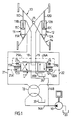
- an oil pump 10 is driven by a motor (not shown).
- the pump supplies two steering piston-cylinder devices 11,12 which are connected to two vehicle-halves 13,14, pivotally connected together on a pivot journal 15.
- the pump supplies pressure oil to a known control valve 16, through a pump line 16A.
- the control valve is connected to the steering wheel of the vehicle and is constructed so that when the steering wheel is turned in one direction the pump is connected, for instance, to the first chamber 11A of one piston-cylinder device 11, while the second chamber 12B of the second piston-cylinder device 12 is connected, at the same time, to the return tank 20.
- the pump is connected to the first chamber 12A of the other piston-cylinder device 12.
- the pump also supplies pressure oil, via a branch line 16B, to a directional valve 17, which is shown in its central position and which can be adjusted to its left or right terminal positions in the figures.
- Each of the piston-cylinder devices has a respective piston 11C and 12C which divide the cylinders of said devices into the first and the second chambers 11A, 11B and 12A, 12B respectively.
- the pistons are connected to the front vehicle-half 13 by means of piston-rods 11D, 12D.
- the control valve 16 is constructed to portion-out oil in volumes corresponding to the angle of valve rotation, which in turn corresponds to given rotation of the vehicle steering wheel and causes the front vehicle-half 13 to be turned to a corresponding extent. Normally, it is necessary to turn the steering wheel through three to four revolutions in order to swing the front vehicle-half from one terminal position to the other.
- the directional valve 17 When the directional valve 17 is adjusted to its central position, the second chambers 11B, 12B of respective piston-cylinder devices are connected, via lines 18,19, to a return line 20B leading to the tank 20.
- the branch line 16B is closed by the directional valve 17, as illustrated in Fig. 1, whereas the pump line 16A can be connected to the first chamber 11A or 12A of the one or the other piston-cylinder device, subsequent to rotating the control valve in one or the other direction from its central position.
- the pressure-controlled directional valve 17 is activated by the pressure prevailing in the line 21, via a branch line 21A, and by the pressure prevailing in the line 22, via a branch line 22A.
- the valve 17 is held in its central position under normal conditions, by two springs 17A and 17B.
- the pump 10 need only supply the one first chamber 11A or the other 12A. Since this suffices for the steering torques required in the majority of conditions, the pump and the control valve may be of considerably smaller dimensions than those required when the steering piston-cylinder devices are permanently cross-coupled in accordance with known techniques.
- the pressure in, for instance, the line 21 will increase and, in certain instances, to an extent such as to exceed the pressure P.
- the spring 17B is unable to resist the higher pressure and the valve 17 will be adjusted to its right terminal-position.
- the branch line 16B of the pump is therewith connected to the line passing to the second chamber 12B of the second piston-cylinder device 12, while the first chamber 11A of the first piston-cylinder device 11 remains connected to the pump.
- the two steering piston-cylinder devices are only cross-connected for the purpose of increasing the steering torque, when these seldomly occurring conditions are found.
- the second chamber 11B of the first piston-cylinder device and the first chamber 12A of the second piston-cylinder device 12 are connected to the tank 20.
- valve 17 when the pressure in the line 22 exceeds the pre-determined pressure value P, the valve 17 will be adjusted to its left terminal-position, so as to cross-couple the steering cylinders for turning the vehicle in the other direction.
- the pressure in the branch line 21A activates the valve 17 via a pilot-area 23, and the pressure in the branch line 22A activates the valve 17 via a pilot-area 24.
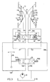
- Fig. 2 illustrates a steering system which coincides essentially with the system illustrated in Fig. 1.
- the pilot-areas 23, 24, 25, 26 of the Fig. 1 embodiment has been omitted from the Fig. 2 embodiment and the pressure in the branch lines 21A, 22A instead acts directly on the spring-operated valve 17, which is controlled by the pressures prevailing in lines 21 and 22 in a manner to steer pressure oil arriving from 16C to the correct chamber 11B or 12B respectively.
- valve 17 oscillation of the valve 17 upon adjustment from its central position is prevented with the aid of a sequence valve or auxiliary valve 27, which is normally in the illustrated left and closed neutral setting, in which the valve interrupts the connection between the branch line 16B of the pump and a pressure line 16C leading to the valve 17.
- the valve 27 can be adjusted from its left position illustrated in Fig. 2 to its right position against the action of a spring 28.
- the valve includes a passage 29, which now connects the lines 16B and 16C together.
- the valve is operated by means of two pilot-areas 30, 31, of which one area 30 is connected to the line 16B, via a line 32, and the other area 31 is connected to the connecting passage 29, via a line 33.
- FIG. 3 illustrates an embodiment in which a control valve 35, which is biased in a direction towards its central position by two springs 35A, 35B, and which is capable of being moved from said central position in either direction by means of a steering stick 34.
- the valve 35 has four ports connected to four lines, of which the line 16A from the pump and a line 20A leading to the tank 20 are connected to one side of the valve in the figure, whereas the lines 21, 22 are connected to the other side of the valve.
- the pump 10 When the valve 35 is moved, for instance, to its right terminal-position with the aid of the stick 34, the pump 10 is connected with the line 21 and with the first chamber 11A of the first piston-cylinder device 11.
- the line 20A is, at the same time, connected to the line 22 which connects the first chamber 12A of the second piston-cylinder device 12 to the tank 20.
- the second chambers 11B, 12B of the two piston-cylinder devices are connected to the tank 20 via the lines 18,19 and the line 20A.
- valve 17 When the pressure in the lines 16A, 16B increases to a value above the pressure P due to an exceptionally large steering torque, the valve 17 will be adjusted to its right terminal-position, with the result described above with reference to Fig. 1.
- the front vehicle-half will continue to turn for as long as the stick 34 is held in one or the other of its terminal positions. This turning movement is interrupted by returning the stick to its central position.
- the advantage of a steering stick in comparison with a rotatable steering wheel is that the stick is less strenuous when working over relatively long periods.
Landscapes
- Engineering & Computer Science (AREA)
- Chemical & Material Sciences (AREA)
- Combustion & Propulsion (AREA)
- Transportation (AREA)
- Mechanical Engineering (AREA)
- Power Steering Mechanism (AREA)
- Steering Control In Accordance With Driving Conditions (AREA)
Claims (3)
- Hydraulisches Lenkungssystem für ein Kraftfahrzeug, welches zwei Fahrzeughälften (13, 14) umfaßt, die über einen Gelenkzapfen (15) gelenkartig untereinander verbunden sind und mit Hilfe von zwei hydraulischen Druckkolbeneinrichtungen verschwenkt werden können, wobei jede von diesen eine erste Kammer (11A, 12A) und eine zweite Kammer (11B, 12B) auf jeweiligen Seiten eines mit einem Kolbenstab (11D, 12D) in den Kolbenzylindereinrichtungen verbundenen Kolbens aufweist, und die mit einer Druckölpumpe (10) über ein Steuerventil (16, 35), welches mittels einer Fahrzeuglenkeinrichtung einstellbar ist und einem Richtungsventil verbunden ist, welches mit Hilfe des Öldrucks auf eine seiner zwei Endpositionen eingestellt werden kann, um so eine gewünschte Verschwenkung der Fahrzeughälften relativ zueinander zu bewirken, und wobei eine Systemeinstellung des Steuerventils, während das Richtungsventil in seiner Mittenposition zwischen den beiden Endpositionen gehalten wird, von einer Mittenposition die erste Kammer (11A oder 12A) einer Kolbenzylindereinrichtung (11 oder 12) veranlaßt, mit der Ölpumpe verbunden zu werden, während die erste Kammer (12A oder 11A) der anderen Kolbenzylindereinrichtung gleichzeitig mit einem Rückführungstank (20) verbunden ist, wodurch die Kolbenzylindereinrichtungen veranlaßt werden als eine einzeln-arbeitende Einrichtung zu arbeiten, wohingegen eine gleichzeitige Einstellung des Richtungsventils (17) auf eine seiner zwei Endpositionen unter dem Einfluß eines Öldrucks in jeweiligen Leitungen zwischen der Pumpe und der ersten Kammer der einen oder der anderen Kolbenzylindereinrichtung eine Verbindung zwischen der Pumpe und der zweiten Kammer (11B, 12B) jeweils der anderen und der einen Kolbenzylindereinrichtung zur Folge hat, so daß die zwei Kolbenzylindereinrichtungen über Kreuz verbunden sind,
dadurch gekennzeichnet, daß
das durch Drucköl in jede Richtung gesteuerte Richtungsventil (17) unter einer Federwirkung (17A, 17B) vorgespannt ist, so daß das Richtungsventil durch Federkräfte in seiner Mittenposition gehalten wird, bis der Öldruck über einen vorgegebenen Wert ansteigt, wodurch bei Öldrucken unterhalb des vorgegebenen Öldrucks und bei entsprechend niedrigen Lenkwiderständen die hydraulischen Kolbenzylindereinrichtungen zur Funktion als einzeln arbeitende Kolbenzylindereinrichtungen gekoppelt werden, wohingegen, wenn der Öldruck als Folge eines entsprechenden Anstiegs des Lenkwiderstands ansteigt, das Richtungsventil (17) auf eine seiner Endpositionen bewegt wird, um so die hydraulischen Kolbenzylindereinrichtungen so zu koppeln, daß sie als doppelt arbeitende Kolbenzylindereinrichtungen arbeiten und Druckleitungen (18, 19) zwischen dem Richtungsventil (17) und den zweiten Kammern (11B, 12B) der zwei Kolbenzylindereinrichtungen verlaufen, wobei die Druckleitungen (18, 19) verzweigt (25A, 26A) sind, um eine Druckwirkung (bei 25, 26) des Richtungsventils (17) auszugleichen, wenn die Position des Ventils auf eine seiner Endpositionen eingestellt wird. - Lenkungssystem nach Anspruch 1,
dadurch gekennzeichnet, daß
in eine Abzweigungsleitung (16B, 16C) zwischen dem Richtungsventil (17) und der Pumpe (10) ein Hilfsventil (27) eingebaut ist, welches mittels Druck in einer Richtung betätigt wird und welches durch eine Feder (28) in einer neutralen Position gehalten wird, in der das Hilfsventil die Verbindung zwischen dem Richtungsventil und der Pumpe unterbricht, wenn das Richtungsventil seine Mittenposition einnimmt und der Druck in der Abzweigungsleitung unter dem vorgegebenen Wert liegt, wohingegen, wenn der Lenkungsöldruck auf einen Pegel größer als der vorgegebene Wert ansteigt, das Hilfsventil (27) entgegen der Wirkung der Feder auf eine offene Position eingestellt wird. - Lenkungssystem nach Anspruch 2,
dadurch gekennzeichnet, daß während einer Einstellung auf seine offene Position im Ansprechen auf eine erste Drucksteuerung (30) das Hilfsventil (27) eine zweite Drucksteuerung (31) aktiviert, wenn das Hilfsventil seine offene Position einnimmt, wobei die Drucksteuerung (31) zur Neutralisierung von Oszillationen des Hilfsventils (27) aufgrund von Druckveränderungen, die auftreten, wenn das Hilfsventil geöffnet wird, arbeitet.
Applications Claiming Priority (3)
| Application Number | Priority Date | Filing Date | Title |
|---|---|---|---|
| SE8803534A SE462277B (sv) | 1988-10-05 | 1988-10-05 | Hydrauliskt styrsystem |
| SE8803534 | 1988-10-05 | ||
| PCT/SE1989/000547 WO1990003909A1 (en) | 1988-10-05 | 1989-10-05 | A hydraulic steering system |
Publications (2)
| Publication Number | Publication Date |
|---|---|
| EP0438435A1 EP0438435A1 (de) | 1991-07-31 |
| EP0438435B1 true EP0438435B1 (de) | 1995-05-10 |
Family
ID=20373529
Family Applications (1)
| Application Number | Title | Priority Date | Filing Date |
|---|---|---|---|
| EP89910965A Expired - Lifetime EP0438435B1 (de) | 1988-10-05 | 1989-10-05 | Hydraulisches lenkungssystem |
Country Status (6)
| Country | Link |
|---|---|
| US (1) | US5193637A (de) |
| EP (1) | EP0438435B1 (de) |
| JP (1) | JP2502776B2 (de) |
| DE (1) | DE68922621T2 (de) |
| SE (1) | SE462277B (de) |
| WO (1) | WO1990003909A1 (de) |
Families Citing this family (17)
| Publication number | Priority date | Publication date | Assignee | Title |
|---|---|---|---|---|
| US5732789A (en) * | 1996-06-24 | 1998-03-31 | Eaton Corporation | Articulated vehicle steering with bogie feedback |
| US6016885A (en) * | 1997-08-22 | 2000-01-25 | Caterpillar Inc. | Steering system |
| CA2691762C (en) | 2004-08-30 | 2012-04-03 | Qualcomm Incorporated | Method and apparatus for an adaptive de-jitter buffer |
| US8085678B2 (en) | 2004-10-13 | 2011-12-27 | Qualcomm Incorporated | Media (voice) playback (de-jitter) buffer adjustments based on air interface |
| US8355907B2 (en) | 2005-03-11 | 2013-01-15 | Qualcomm Incorporated | Method and apparatus for phase matching frames in vocoders |
| US8155965B2 (en) | 2005-03-11 | 2012-04-10 | Qualcomm Incorporated | Time warping frames inside the vocoder by modifying the residual |
| US7555855B2 (en) * | 2005-03-31 | 2009-07-07 | Caterpillar Inc. | Automatic digging and loading system for a work machine |
| US7434653B2 (en) * | 2005-03-31 | 2008-10-14 | Caterpillar Inc. | On-demand electro-hydraulic steering system |
| US20070246288A1 (en) * | 2006-04-24 | 2007-10-25 | Mather Daniel T | Dual force hydraulic steering system for articulated work machine |
| US7979181B2 (en) | 2006-10-19 | 2011-07-12 | Caterpillar Inc. | Velocity based control process for a machine digging cycle |
| US8413572B1 (en) | 2006-11-22 | 2013-04-09 | Westendorf Manufacturing, Co. | Auto attachment coupler with abductor valve |
| NL1037274C2 (nl) * | 2009-09-11 | 2011-03-14 | Advanced Public Transp Systems B V | Stuurinrichting voor een vooraf gedefinieerd traject verplaatsbaar voertuig, automatisch gestuurd en via tenminste een eerste as , alsmede een voertuig voorzien van een dergelijke stuurinrichting. |
| CN110242638A (zh) * | 2012-11-20 | 2019-09-17 | 沃尔沃建筑设备公司 | 加压介质组件 |
| RU2547966C1 (ru) * | 2014-03-11 | 2015-04-10 | Юрий Феликсович Черняков | Рулевая система управления трактором поворотом полурам |
| RU2555875C1 (ru) * | 2014-05-05 | 2015-07-10 | Юрий Феликсович Черняков | Рулевая система поворота балки моста и полурам трактора |
| US9340954B2 (en) * | 2014-09-22 | 2016-05-17 | Deere & Company | Regenerative circuit for articulated joint |
| AU2017326752B2 (en) | 2016-09-15 | 2023-06-01 | Terex Australia Pty Ltd | Crane counterweight and suspension |
Family Cites Families (8)
| Publication number | Priority date | Publication date | Assignee | Title |
|---|---|---|---|---|
| DE1942086C3 (de) * | 1969-08-19 | 1981-10-01 | Zahnradfabrik Friedrichshafen Ag, 7990 Friedrichshafen | Hydrostatische Hilfskraftlenkeinrichtung, insbesondere für Kraftfahrzeuge |
| DE2110725C2 (de) * | 1971-03-06 | 1984-04-26 | Zahnradfabrik Friedrichshafen Ag, 7990 Friedrichshafen | Hydraulische Hilfskraftlenkung für Kraftfahrzeuge |
| JPS5140700B2 (de) * | 1972-06-02 | 1976-11-05 | ||
| DE2516771A1 (de) * | 1975-04-16 | 1976-10-28 | Zahnradfabrik Friedrichshafen | Hydrostatische hilfskraftlenkung, insbesondere fuer kraftfahrzeuge |
| JPS51140924U (de) * | 1975-05-06 | 1976-11-13 | ||
| US4081961A (en) * | 1977-04-06 | 1978-04-04 | Massey-Ferguson Inc. | Articulated vehicle steering system |
| JPS558681A (en) * | 1978-07-05 | 1980-01-22 | Shinwa Shoko Kk | Tape winding completion detection unit of cassette-type tape recorder |
| SU761345A1 (ru) * | 1978-11-27 | 1980-09-07 | Aleksandr B Nikitin | Гидравлическое рулевое управление транспортного средства с шарнирносочлененной рамой 1 |
-
1988
- 1988-10-05 SE SE8803534A patent/SE462277B/sv not_active IP Right Cessation
-
1989
- 1989-10-05 EP EP89910965A patent/EP0438435B1/de not_active Expired - Lifetime
- 1989-10-05 JP JP1510263A patent/JP2502776B2/ja not_active Expired - Lifetime
- 1989-10-05 US US07/668,507 patent/US5193637A/en not_active Expired - Lifetime
- 1989-10-05 WO PCT/SE1989/000547 patent/WO1990003909A1/en not_active Ceased
- 1989-10-05 DE DE68922621T patent/DE68922621T2/de not_active Expired - Lifetime
Also Published As
| Publication number | Publication date |
|---|---|
| JP2502776B2 (ja) | 1996-05-29 |
| DE68922621T2 (de) | 1995-09-28 |
| DE68922621D1 (de) | 1995-06-14 |
| SE8803534D0 (sv) | 1988-10-05 |
| JPH04500944A (ja) | 1992-02-20 |
| SE8803534L (sv) | 1990-04-06 |
| EP0438435A1 (de) | 1991-07-31 |
| WO1990003909A1 (en) | 1990-04-19 |
| SE462277B (sv) | 1990-05-28 |
| US5193637A (en) | 1993-03-16 |
Similar Documents
| Publication | Publication Date | Title |
|---|---|---|
| EP0438435B1 (de) | Hydraulisches lenkungssystem | |
| KR100556570B1 (ko) | 유압식스티어링장치및그유압밸브 | |
| US4756543A (en) | Arrangement for controlled damping of pivoting movements in an articulated bus | |
| US5732789A (en) | Articulated vehicle steering with bogie feedback | |
| US5718304A (en) | Four-wheel steering system for vehicle | |
| US4372413A (en) | Hydrostatic steering device | |
| US4019596A (en) | Synchronous control system | |
| US6655492B2 (en) | Steering system and method for steering a vehicle | |
| EP0653342B1 (de) | Hydraulische Servolenkung | |
| US4016949A (en) | Hydrostatic load sensitive regenerative steering system | |
| US4313615A (en) | Buckling angle control arrangement for an articulated vehicle | |
| US4071108A (en) | Steering system for articulated vehicles | |
| EP0446785B1 (de) | Hydraulisches Steuerventil | |
| RU2031033C1 (ru) | Гидросистема рулевого управления транспортного средства | |
| RU2062374C1 (ru) | Гидросистема самоходной машины | |
| JPH0743532Y2 (ja) | 油圧伝動装置 | |
| EP0938424B1 (de) | Lenkung für ein fahrzeug mit knickrahmen | |
| US5297647A (en) | Variable assist power steering gear with hydraulic reaction controls | |
| US4846296A (en) | Hydraulic fluid pressure control system for use with power assist steering | |
| JPH0379474A (ja) | 全油圧式パワーステアリング装置 | |
| US4953416A (en) | Power steering valve with two spools of different size to compensate unbalanced cylinder | |
| EP0721412B1 (de) | Hydraulischer steuerkreis für einen hilfskraftunterstützten lenkmechanismus eines fahrzeugs | |
| JP2559724B2 (ja) | パワ−ステアリングの油圧制御装置 | |
| JPH0238430B2 (de) | ||
| RU2102268C1 (ru) | Гидравлическая система рулевого управления колесного транспортного средства |
Legal Events
| Date | Code | Title | Description |
|---|---|---|---|
| PUAI | Public reference made under article 153(3) epc to a published international application that has entered the european phase |
Free format text: ORIGINAL CODE: 0009012 |
|
| 17P | Request for examination filed |
Effective date: 19910226 |
|
| AK | Designated contracting states |
Kind code of ref document: A1 Designated state(s): BE DE FR GB |
|
| 17Q | First examination report despatched |
Effective date: 19930624 |
|
| GRAA | (expected) grant |
Free format text: ORIGINAL CODE: 0009210 |
|
| AK | Designated contracting states |
Kind code of ref document: B1 Designated state(s): BE DE FR GB |
|
| REF | Corresponds to: |
Ref document number: 68922621 Country of ref document: DE Date of ref document: 19950614 |
|
| ET | Fr: translation filed | ||
| PLBE | No opposition filed within time limit |
Free format text: ORIGINAL CODE: 0009261 |
|
| STAA | Information on the status of an ep patent application or granted ep patent |
Free format text: STATUS: NO OPPOSITION FILED WITHIN TIME LIMIT |
|
| 26N | No opposition filed | ||
| REG | Reference to a national code |
Ref country code: GB Ref legal event code: IF02 |
|
| PGFP | Annual fee paid to national office [announced via postgrant information from national office to epo] |
Ref country code: DE Payment date: 20081014 Year of fee payment: 20 |
|
| PGFP | Annual fee paid to national office [announced via postgrant information from national office to epo] |
Ref country code: BE Payment date: 20081009 Year of fee payment: 20 |
|
| PGFP | Annual fee paid to national office [announced via postgrant information from national office to epo] |
Ref country code: FR Payment date: 20081014 Year of fee payment: 20 |
|
| PGFP | Annual fee paid to national office [announced via postgrant information from national office to epo] |
Ref country code: GB Payment date: 20081001 Year of fee payment: 20 |
|
| REG | Reference to a national code |
Ref country code: GB Ref legal event code: PE20 Expiry date: 20091004 |
|
| BE20 | Be: patent expired |
Owner name: *VME INDUSTRIES SWEDEN A.B. Effective date: 20091005 |
|
| PG25 | Lapsed in a contracting state [announced via postgrant information from national office to epo] |
Ref country code: GB Free format text: LAPSE BECAUSE OF EXPIRATION OF PROTECTION Effective date: 20091004 |