EP0437833A2 - Automatic and interactive power controller for audio/video systems - Google Patents
Automatic and interactive power controller for audio/video systems Download PDFInfo
- Publication number
- EP0437833A2 EP0437833A2 EP90125470A EP90125470A EP0437833A2 EP 0437833 A2 EP0437833 A2 EP 0437833A2 EP 90125470 A EP90125470 A EP 90125470A EP 90125470 A EP90125470 A EP 90125470A EP 0437833 A2 EP0437833 A2 EP 0437833A2
- Authority
- EP
- European Patent Office
- Prior art keywords
- time interval
- predetermined time
- timer
- control means
- source
- Prior art date
- Legal status (The legal status is an assumption and is not a legal conclusion. Google has not performed a legal analysis and makes no representation as to the accuracy of the status listed.)
- Granted
Links
- 230000002452 interceptive effect Effects 0.000 title 1
- 230000004044 response Effects 0.000 claims abstract description 10
- 230000000007 visual effect Effects 0.000 claims abstract description 6
- 230000007423 decrease Effects 0.000 claims abstract description 5
- 230000003247 decreasing effect Effects 0.000 claims description 3
- 230000005236 sound signal Effects 0.000 claims description 3
- 230000004913 activation Effects 0.000 claims 1
- 238000005286 illumination Methods 0.000 claims 1
- 230000004622 sleep time Effects 0.000 abstract description 10
- 230000006870 function Effects 0.000 description 26
- 230000005540 biological transmission Effects 0.000 description 6
- 230000007704 transition Effects 0.000 description 3
- 238000000034 method Methods 0.000 description 2
- 230000008569 process Effects 0.000 description 2
- 230000009471 action Effects 0.000 description 1
- 230000003321 amplification Effects 0.000 description 1
- 238000010586 diagram Methods 0.000 description 1
- 238000011038 discontinuous diafiltration by volume reduction Methods 0.000 description 1
- 239000004973 liquid crystal related substance Substances 0.000 description 1
- 238000003199 nucleic acid amplification method Methods 0.000 description 1
- 230000009467 reduction Effects 0.000 description 1
Images


Classifications
-
- H—ELECTRICITY
- H04—ELECTRIC COMMUNICATION TECHNIQUE
- H04N—PICTORIAL COMMUNICATION, e.g. TELEVISION
- H04N21/00—Selective content distribution, e.g. interactive television or video on demand [VOD]
- H04N21/40—Client devices specifically adapted for the reception of or interaction with content, e.g. set-top-box [STB]; Operations thereof
- H04N21/47—End-user applications
- H04N21/485—End-user interface for client configuration
-
- H—ELECTRICITY
- H04—ELECTRIC COMMUNICATION TECHNIQUE
- H04N—PICTORIAL COMMUNICATION, e.g. TELEVISION
- H04N5/00—Details of television systems
- H04N5/44—Receiver circuitry for the reception of television signals according to analogue transmission standards
- H04N5/60—Receiver circuitry for the reception of television signals according to analogue transmission standards for the sound signals
-
- G—PHYSICS
- G04—HOROLOGY
- G04G—ELECTRONIC TIME-PIECES
- G04G15/00—Time-pieces comprising means to be operated at preselected times or after preselected time intervals
- G04G15/006—Time-pieces comprising means to be operated at preselected times or after preselected time intervals for operating at a number of different times
-
- H—ELECTRICITY
- H04—ELECTRIC COMMUNICATION TECHNIQUE
- H04N—PICTORIAL COMMUNICATION, e.g. TELEVISION
- H04N21/00—Selective content distribution, e.g. interactive television or video on demand [VOD]
- H04N21/40—Client devices specifically adapted for the reception of or interaction with content, e.g. set-top-box [STB]; Operations thereof
- H04N21/47—End-user applications
-
- H—ELECTRICITY
- H04—ELECTRIC COMMUNICATION TECHNIQUE
- H04N—PICTORIAL COMMUNICATION, e.g. TELEVISION
- H04N5/00—Details of television systems
- H04N5/63—Generation or supply of power specially adapted for television receivers
Definitions
- This invention concerns consumer electronic equipment having an automatic sleep timer function.
- consumer electronic equipment includes television receivers, videodisc players, video tape players (VTPs), compact disc players (CDs), and radios.
- television receiver includes television receivers having a display device (commonly known as television sets) and television receivers without a display device such as VCRs.
- Many modern television receivers include a so-called sleep timer function for automatically turning the receiver off after a predetermined time interval set by a user.
- the sleep timer function allows a user to conserve power by shutting off the television receiver automatically if the user has fallen asleep.
- Such a sleep function is known from, for example, RCA CTC-140 type television receivers manufactured by Thomson Consumer Electronics Incorporated, Indianapolis, Indiana.
- a related common problem which occurs especially in households with small children, is the problem of wasted power due to unattended operation of a television receiver (or other consumer electronics equipment). That is, it frequently happens that children will turn on a television receiver, become distracted, and leave the room to play elsewhere. In this situation, conventional sleep timer capability in the television receiver would not solve the problem. This is so, because conventional sleep timers must be enabled in some fashion to become active and begin timing the timeout period. Since children, it seems, cannot be expected to turn off the receiver, they certainly cannot be expected to perform the more complex task of enabling a sleep timer function.
- the subject invention resides in part in the recognition that it is desirable that a sleep timer function be reset and restarted in response to an indication that the user is still awake. It is herein recognized that operation of a remote control by a user, for any reason, provides a clear indication to the sleep function controller that the user is still awake. Consequently, apparatus in accordance with the invention resets the time delay period of the sleep timer and restarts the timer, whenever it receives a transmission from a remote control transmitter unit.
- any remote control transmitter unit for controlling any device such as a VCR associated with the television receiver
- any device such as a VCR associated with the television receiver
- IR modulated infrared
- the television receiver provide an audible, or visual, indication that it is about to automatically turn off.
- volume can be automatically reduced to a level near zero before turning off the receiver. It is also herein recognized that such volume reduction should not affect the volume level to be restored when the receiver is next turned on..
- a sleep timer feature should not have to be deliberately enabled by a user. Accordingly, in one embodiment the timer is enabled automatically when the receiver is turned on. In another embodiment the sleep timer is enabled only during a preset time portion of the day. In one embodiment, the sleep time interval is fixed. In another embodiment, the sleep time interval is user presettable.
- FIGURE 1 is a block diagram of a portion of a television receiver suitable for implementing the invention.
- FIGURE 2 is a simplified flow chart of a portion of the control program suitable for controlling the microprocessor of FIGURE 1.
- FIGURE 3 is a more detailed flow chart of a portion of a program suitable for controlling the microprocessor of FIGURE 1.
- FIGURES 4-6 illustrate a display screens having indicia displayed thereon which are suitable for use with the invention.
- a television receiver includes an RF input terminal 100 which receives radio frequency (RF) signals and applies them to a tuner assembly 102.
- Tuner assembly 102 selects and amplifies a particular RF signal under control of a tuner controller 104 which provides a tuning voltage via a wire 103, and bandswitching signals via signal lines represented by the broad double-ended arrow 103', to tuner assembly 102.
- RF radio frequency
- Tuner assembly 102 converts the received RF signal to an intermediate frequency (IF) signal and provides an IF output signal to video (VIF) and sound (SIF) amplifier and detector unit 108.
- VIF/SIF amplifier and detector unit 108 amplifies the IF signal applied to its input terminal and detects the video and audio information contained therein.
- the detected video information is applied as one input of a video processor unit 122.
- the other input of video processor unit 122 is connected to an on-screen display circuit 124.
- the detected audio signal is applied to an audio processor 106 for processing and amplification before being applied to a speaker (not shown).
- Tuner controller 104 generates the tuning voltage and bandswitching signals in response to control signals applied from a system control microcomputer ( ⁇ C) 110.
- ⁇ C system control microcomputer
- microcomputer controller, and “microprocessor”, as used herein, are equivalent. It is also recognized that the control function of microcomputer 110 may be performed by an integrated circuit especially manufactured for that specific purpose (i.e., a "custom chip"), and the term “controller”, as used herein, is also intended to include such a device.
- Microcomputer 110 receives user-initiated commands from an infrared (IR) receiver 119 and from a "local" keyboard 118 mounted on the television receiver itself.
- IR receiver 119 receives IR transmissions from remote control transmitter 126.
- Microcomputer 110 includes program memory (ROM) 112, and stores channel-related data in a random-access memory (RAM) 120.
- RAM 120 may be either internal to, or external to, microprocessor 110, and may be of either the volatile or non-volatile type.
- RAM is also intended to include electrically-erasable programmable read only memory (EEPROM).
- EEPROM electrically-erasable programmable read only memory
- Microcomputer 110 operates from a source of standby power 155, and controls a source of operating power 150 for selectively applying power to the remainder of the television receiver.
- Microcomputer 110 includes a real time clock 113 for keeping time of day.
- Microcomputer 110 also includes a timer 114 the operation of which will be described below.
- Microcomputer 110 is also coupled, via a wire 111 to a digital-to-analog (D/A) converter unit 130. Under microprocessor control, D/A unit 130 generates a control signal for controlling the level of volume produced by audio processor 106 and its associated speaker.
- D/A digital-to-analog
- the television receiver described thusfar is known, for example, from the RCA CTC-140 color television manufactured by Thomson Consumer Electronics, Inc., Indianapolis, Indiana.
- TIMER 114 of FIGURE 1 times a fixed predetermined time interval which may be, for example, 30 minutes. Alternatively, a user may enter a predetermined time interval of his own choosing. Because ease of use is an important concern, it is desirable that the enabling of TIMER 114 should require no separate action by the user. Therefore, in one embodiment, TIMER 114 is enabled automatically when the television receiver is turned on. It is recognized that, in some instances, it may be undesirable to have the sleep timer always enabled. For those instances, remote control unit 126 may include a SLEEP TIMER ON/OFF key.
- the first operation of the SLEEP TIMER ON/OFF key disables the sleep timer function until the next operation of the SLEEP TIMER key, which reenables the sleep timer function.
- the sleep timer function may be enabled, in accordance with signals from a real time clock 113, only during a predetermined portion of the day. For example, the sleep timer might only be enabled from 11:00 pm until 6:00 am, when the user would be most apt to fall asleep with the television receiver still turned on. If, however, the sleep timer is enabled at all times, then it may not be necessary to include real time clock 113 for the sleep timer function.
- the portion of the control program illustrated in FIGURE 2 is entered at step 200 from other portions of the control program, such as tuner control and keyboard decoding, which are not pertinent to the subject invention, and therefore need not be explained in detail.
- IR infrared
- the IR detector normally used for the reception of IR remote control signals is also used for this purpose as follows.
- the IR detector will include a bandpass filter centered at the IR frequency of interest followed by an envelope detector, such as an integrator, for producing an electrical pulse signal corresponding to the modulation of the received IR signal.
- an envelope detector such as an integrator
- microprocessor 110 samples the pulse signal to detect the "high” and “low” portions. For the purpose of step 205, it is not necessary to fully decode the pulse signal, and it is sufficient to determine the presence of a sequence of "highs" and "lows".
- the IR detector will include a bandpass filter centered at the IR frequency range of interest followed by a transition detector, such as a differentiator, for producing a an electrical signal having transitions at the same frequency as the received IR signal.
- a transition detector such as a differentiator
- microprocessor 110 determines the time interval between the transitions to determine the frequency of IR signal. As in the case of a pulse encoded IR signal, for the purpose of step 205, it is not necessary to decode the remote control signal. In this case it is sufficient to determine if the bandpass filter produces an output signal of the proper level.
- TIMER 114 be reset in response to the presence of modulated IR from remote control transmitters for controlling other devices associated with the television receiver. Since different types of IR modulation may be used, it may be desirable to make provisions for detecting both the pulse and the frequency types of IR modulation. If an IR signal has not been detected, the program advances to step 210 wherein a check is made to see if TIMER 114 is running. If not, the current volume level selected by the user is stored (step 215) in a power-on volume register 134, and the routine is exited at step 220. Power-on volume register 134 holds the volume setting at which the receiver was operating just before it was last manually turned-off by the user. Register 134 is read at power-on so that the last volume setting can be restored automatically.
- TIMER 114 if it is determined at step 210 that TIMER 114 is running then a check is made to see if the time interval is near expiration (i.e., two minutes or less remaining of the 30 minute sleep time interval)(step 225). If not, the current volume level is stored in power-on volume register 134 to make sure that the volume level data is up-to-date and accurate, and the routine exited. Each time the controller "loops through" this portion of the control program, the controller checks the time remaining in the sleep time interval.
- controller 110 begins to decrement the volume setting stored in ramp-down volume register 132 at a fixed interval (perhaps once every second), which causes the volume to slowly "ramp" down. This is done to prevent a sleeping, or near sleeping, user from being awakened by a sudden cessation of sound when the television receiver is turned off.
- the volume level stored in ramp-down volume register 132 is checked to see if it has been reduced to zero. If not, the routine is exited. If so, the power to the television receiver is turned off (step 240).
- IR is detected at step 205, then the volume is reset to the last level set by the user, that is, the value stored in power-on register 134 is read and stored in ramp-down register 132. TIMER 114 is then reset, and begins timing the interval again.
- a ramping down i.e. gradual reduction
- the volume or a visual indication on the display screen of the receiver
- the normal reaction of a user would be to pick up the remote control and to attempt to restore the proper volume.
- the act of utilizing the remote control, or the local keyboard, is interpreted by the apparatus of the subject invention as an indication that the user is still awake, and causes the sleep timer to be reset and restarted.
- the IR command does not have to be decoded at this stage because reception of any modulated IR signal (decodable in the television receiver or not) is taken to mean that the user is still awake, and does not want his viewing of the television program disturbed.
- an attempt is made to decode the modulated IR signal. If it is the STOP TIMER code, then TIMER 114 is stopped (step 260). If not, further decoding is performed in a keycode decoding routine, which is known, per se.
- some known cable decoder units provide volume control via IR remote control signals. If a television receiver incorporating the subject invention were to be coupled to such a cable decoder unit, the following operation would occur. During the final two minutes of the sleep time interval, the television receiver would begin to gradually reduce the audio volume and the user would naturally pick up the remote control for the cable decoder unit to correct for the reduced volume. Due to different encoding and modulation schemes employed by individual manufacturers, the user's television receiver would most likely be unable to decode the remote control message transmitted by his cable decoder remote control unit. Nevertheless, the sleep timer controller of the television receiver would recognize that a modulated IR signal was transmitted, and would in response thereto, reset the volume level and the reset the sleep timer.
- the subject apparatus may be included in television sets, VCR's, and other signal sources such as video tape players, or videodisc players. If so, then a user may watch a program from one of these sources and have each element of his system shut down individually, if he falls asleep.
- a television receiver may be equipped with a controlled power outlet 140 for providing AC power via a receptacle 142 to other system components. If such a receiver were also equipped with the above-described sleep function circuitry, then the automatic turn-off feature would be made available to any apparatus plugged into the controlled outlet, which would cause the turning off of both units simultaneously.
- Controlled outlet 140 is illustrated for purposes of simplicity as incorporating an electromechanical relay 144. It may, of course, be controlled via solid-state switching circuitry instead.
- FIGURE 3 is a more detailed flowchart of a program suitable for use with the invention.
- the section of FIGURE 3 generally designated 310 serves substantially the same purpose as blocks 205, 210, 215,and 245 of the flowchart of FIGURE 2.
- the section of FIGURE 3 generally designated 320 serves substantially the same purpose as blocks 250 and 260 of the flowchart of FIGURE 2.
- the section of FIGURE 330 generally designated 330 serves substantially the same purpose as blocks 225, 230, 235, and 240 of the flowchart of FIGURE 2.
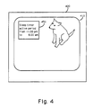
- FIGURE 3 The area of FIGURE 3 generally designated 340 allows a user to specify a time interval, or "window" within which the sleep function circuitry is enabled. It is envisioned that a television receiver having a sleep function in accordance with the present invention may make use of either dedicated keys on a keyboard, or selections from a menu, for entering instructions as to the sleep function active interval. As shown in FIGURE 4, for purposes of programming the sleep function window, a sleep function instruction screen is displayed along with the video on a display screen in response to the aforementioned pressing of a dedicated key for recalling such a display, or in response to the selection from a menu of that particular function. In the either case, FIGURE 4 shows a display in which the user has already entered data which will cause the sleep timer to be active between the hours of 11:00 pm and 6:00 am which are the most likely hours in which a viewer might fall asleep with the television receiver still turned on.
- the viewer may become interested in the television program and remain awake.
- using decreasing volume as a warning signal naturally causes the user to pick up the remote control transmitter to correct for the decrease volume.
- the very act of correcting the volume is the act (i.e., starting an IR transmission) which is required to reset the sleep function.
- FIGURES 5 and 6 illustrate two warning indications suitable for display on a display screen (in addition to, or in place of a decrease of volume), during, for example, the final two minutes of the sleep time interval.
- a bar graph 520 is displayed along with the video on a screen 510 of a television receiver 500.
- the bar may be indicative of time remaining until turn off.
- the visual display may indicate current audio volume level.
- FIGURE 6 illustrates a screen display in which the bar graph of FIGURE 5 has been replaced with a "time remaining" display 630.
- FIGURE 6 also shows an LED, liquid crystal display (LCD), or lamp 640 which, when illuminated, for example during the final two minutes of the sleep time interval, could serve as a visual sleep-function automatic turn-off warning in television receivers without on-screen display capability.
- LCD liquid crystal display
Landscapes
- Engineering & Computer Science (AREA)
- Multimedia (AREA)
- Signal Processing (AREA)
- Physics & Mathematics (AREA)
- General Physics & Mathematics (AREA)
- Human Computer Interaction (AREA)
- Selective Calling Equipment (AREA)
- Television Receiver Circuits (AREA)
- Details Of Television Systems (AREA)
- Direct Current Feeding And Distribution (AREA)
- Electric Clocks (AREA)
- Two-Way Televisions, Distribution Of Moving Picture Or The Like (AREA)
- Power Sources (AREA)
Abstract
Description
- This invention concerns consumer electronic equipment having an automatic sleep timer function.
- The term consumer electronic equipment, as used herein, includes television receivers, videodisc players, video tape players (VTPs), compact disc players (CDs), and radios. The term television receiver, as used herein, includes television receivers having a display device (commonly known as television sets) and television receivers without a display device such as VCRs.
- Many modern television receivers include a so-called sleep timer function for automatically turning the receiver off after a predetermined time interval set by a user. The sleep timer function allows a user to conserve power by shutting off the television receiver automatically if the user has fallen asleep. Such a sleep function is known from, for example, RCA CTC-140 type television receivers manufactured by Thomson Consumer Electronics Incorporated, Indianapolis, Indiana.
- Unfortunately, even though a user has set a predetermined time for the television to automatically turn off the user may not fall asleep, but rather may become interested in the program and remain awake. In this case, the user may forget that the sleep timer is enabled, and then find to his surprise that the television automatically turns itself off.
- A related common problem, which occurs especially in households with small children, is the problem of wasted power due to unattended operation of a television receiver (or other consumer electronics equipment). That is, it frequently happens that children will turn on a television receiver, become distracted, and leave the room to play elsewhere. In this situation, conventional sleep timer capability in the television receiver would not solve the problem. This is so, because conventional sleep timers must be enabled in some fashion to become active and begin timing the timeout period. Since children, it seems, cannot be expected to turn off the receiver, they certainly cannot be expected to perform the more complex task of enabling a sleep timer function.
- The subject invention resides in part in the recognition that it is desirable that a sleep timer function be reset and restarted in response to an indication that the user is still awake. It is herein recognized that operation of a remote control by a user, for any reason, provides a clear indication to the sleep function controller that the user is still awake. Consequently, apparatus in accordance with the invention resets the time delay period of the sleep timer and restarts the timer, whenever it receives a transmission from a remote control transmitter unit.
- It is also herein recognized that operation of any remote control transmitter unit for controlling any device, such as a VCR associated with the television receiver, provides a detectable indication that the user is awake. For this reason, reception of modulated infrared (IR) signals from any remote control unit will be accepted by the subject apparatus for the purpose of resetting the sleep timer.
- It is further herein recognized that it is desirable that the television receiver provide an audible, or visual, indication that it is about to automatically turn off.
- It is also herein recognized that the volume can be automatically reduced to a level near zero before turning off the receiver. It is also herein recognized that such volume reduction should not affect the volume level to be restored when the receiver is next turned on..
- Additionally, it is herein recognized that a sleep timer feature should not have to be deliberately enabled by a user. Accordingly, in one embodiment the timer is enabled automatically when the receiver is turned on. In another embodiment the sleep timer is enabled only during a preset time portion of the day. In one embodiment, the sleep time interval is fixed. In another embodiment, the sleep time interval is user presettable.
- FIGURE 1 is a block diagram of a portion of a television receiver suitable for implementing the invention.
- FIGURE 2 is a simplified flow chart of a portion of the control program suitable for controlling the microprocessor of FIGURE 1.
- FIGURE 3 is a more detailed flow chart of a portion of a program suitable for controlling the microprocessor of FIGURE 1.
- FIGURES 4-6 illustrate a display screens having indicia displayed thereon which are suitable for use with the invention.
- Referring to FIGURE 1, a television receiver includes an
RF input terminal 100 which receives radio frequency (RF) signals and applies them to atuner assembly 102.Tuner assembly 102 selects and amplifies a particular RF signal under control of atuner controller 104 which provides a tuning voltage via awire 103, and bandswitching signals via signal lines represented by the broad double-ended arrow 103', totuner assembly 102. -
Tuner assembly 102 converts the received RF signal to an intermediate frequency (IF) signal and provides an IF output signal to video (VIF) and sound (SIF) amplifier and detector unit 108. VIF/SIF amplifier and detector unit 108 amplifies the IF signal applied to its input terminal and detects the video and audio information contained therein. The detected video information is applied as one input of avideo processor unit 122. The other input ofvideo processor unit 122 is connected to an on-screen display circuit 124. The detected audio signal is applied to anaudio processor 106 for processing and amplification before being applied to a speaker (not shown). -
Tuner controller 104 generates the tuning voltage and bandswitching signals in response to control signals applied from a system control microcomputer (µC) 110. The terms "microcomputer", controller, and "microprocessor", as used herein, are equivalent. It is also recognized that the control function ofmicrocomputer 110 may be performed by an integrated circuit especially manufactured for that specific purpose (i.e., a "custom chip"), and the term "controller", as used herein, is also intended to include such a device.Microcomputer 110 receives user-initiated commands from an infrared (IR)receiver 119 and from a "local" keyboard 118 mounted on the television receiver itself.IR receiver 119 receives IR transmissions from remote control transmitter 126.Microcomputer 110 includes program memory (ROM) 112, and stores channel-related data in a random-access memory (RAM) 120.RAM 120 may be either internal to, or external to,microprocessor 110, and may be of either the volatile or non-volatile type. The term "RAM" is also intended to include electrically-erasable programmable read only memory (EEPROM). One skilled in the art will recognize that if volatile memory is utilized, that it may be desirable to use a suitable form of standby power to preserve its contents when the receiver is turned off. - Microcomputer 110 operates from a source of
standby power 155, and controls a source ofoperating power 150 for selectively applying power to the remainder of the television receiver.Microcomputer 110 includes areal time clock 113 for keeping time of day.Microcomputer 110 also includes atimer 114 the operation of which will be described below.Microcomputer 110 is also coupled, via a wire 111 to a digital-to-analog (D/A)converter unit 130. Under microprocessor control, D/A unit 130 generates a control signal for controlling the level of volume produced byaudio processor 106 and its associated speaker. - The television receiver described thusfar is known, for example, from the RCA CTC-140 color television manufactured by Thomson Consumer Electronics, Inc., Indianapolis, Indiana.
- The invention will now be described with reference to the remainder of FIGURE 1, and the flow chart of FIGURE 2.
- Preferably,
TIMER 114 of FIGURE 1 times a fixed predetermined time interval which may be, for example, 30 minutes. Alternatively, a user may enter a predetermined time interval of his own choosing. Because ease of use is an important concern, it is desirable that the enabling ofTIMER 114 should require no separate action by the user. Therefore, in one embodiment,TIMER 114 is enabled automatically when the television receiver is turned on. It is recognized that, in some instances, it may be undesirable to have the sleep timer always enabled. For those instances, remote control unit 126 may include a SLEEP TIMER ON/OFF key. The first operation of the SLEEP TIMER ON/OFF key disables the sleep timer function until the next operation of the SLEEP TIMER key, which reenables the sleep timer function. In another embodiment, the sleep timer function may be enabled, in accordance with signals from areal time clock 113, only during a predetermined portion of the day. For example, the sleep timer might only be enabled from 11:00 pm until 6:00 am, when the user would be most apt to fall asleep with the television receiver still turned on. If, however, the sleep timer is enabled at all times, then it may not be necessary to includereal time clock 113 for the sleep timer function. - Assuming that the timer is enabled, if no modulated IR signals are detected during the 30 minute sleep time interval, the receiver is turned off. If modulated IR signals are detected during the 30 minute interval, then
TIMER 114 is reset, and begins timing a new 30 minute interval. This process may be repeated several times. The flowcharts of FIGURES 2 and 3 describe in different levels of detail a program for accomplishing this function, as well as other functions described below. - The portion of the control program illustrated in FIGURE 2 is entered at step 200 from other portions of the control program, such as tuner control and keyboard decoding, which are not pertinent to the subject invention, and therefore need not be explained in detail.
- A determination is made at
step 205 as to whether or not a modulated infrared (IR) signal has been detected. The IR detector normally used for the reception of IR remote control signals is also used for this purpose as follows. - If the remote control signals are encoded utilizing some form of pulse code, the IR detector will include a bandpass filter centered at the IR frequency of interest followed by an envelope detector, such as an integrator, for producing an electrical pulse signal corresponding to the modulation of the received IR signal. To decode a remote control command,
microprocessor 110 samples the pulse signal to detect the "high" and "low" portions. For the purpose ofstep 205, it is not necessary to fully decode the pulse signal, and it is sufficient to determine the presence of a sequence of "highs" and "lows". - If the remote control signals are encoded utilizing frequency modulation, the IR detector will include a bandpass filter centered at the IR frequency range of interest followed by a transition detector, such as a differentiator, for producing a an electrical signal having transitions at the same frequency as the received IR signal. To decode a remote control signal,
microprocessor 110 determines the time interval between the transitions to determine the frequency of IR signal. As in the case of a pulse encoded IR signal, for the purpose ofstep 205, it is not necessary to decode the remote control signal. In this case it is sufficient to determine if the bandpass filter produces an output signal of the proper level. - For the reasons to be explained below, it is desirable that
TIMER 114 be reset in response to the presence of modulated IR from remote control transmitters for controlling other devices associated with the television receiver. Since different types of IR modulation may be used, it may be desirable to make provisions for detecting both the pulse and the frequency types of IR modulation. If an IR signal has not been detected, the program advances to step 210 wherein a check is made to see ifTIMER 114 is running. If not, the current volume level selected by the user is stored (step 215) in a power-onvolume register 134, and the routine is exited atstep 220. Power-onvolume register 134 holds the volume setting at which the receiver was operating just before it was last manually turned-off by the user.Register 134 is read at power-on so that the last volume setting can be restored automatically. - Referring again to the FIGURES, if it is determined at
step 210 thatTIMER 114 is running then a check is made to see if the time interval is near expiration (i.e., two minutes or less remaining of the 30 minute sleep time interval)(step 225). If not, the current volume level is stored in power-onvolume register 134 to make sure that the volume level data is up-to-date and accurate, and the routine exited. Each time the controller "loops through" this portion of the control program, the controller checks the time remaining in the sleep time interval. If the time remaining in the sleep time interval is two minutes or less (step 225), thencontroller 110 begins to decrement the volume setting stored in ramp-downvolume register 132 at a fixed interval (perhaps once every second), which causes the volume to slowly "ramp" down. This is done to prevent a sleeping, or near sleeping, user from being awakened by a sudden cessation of sound when the television receiver is turned off. Atstep 235, the volume level stored in ramp-downvolume register 132 is checked to see if it has been reduced to zero. If not, the routine is exited. If so, the power to the television receiver is turned off (step 240). - If IR is detected at
step 205, then the volume is reset to the last level set by the user, that is, the value stored in power-onregister 134 is read and stored in ramp-down register 132.TIMER 114 is then reset, and begins timing the interval again. - During the final two minutes of the sleep timer interval, a ramping down (i.e. gradual reduction) of the volume, or a visual indication on the display screen of the receiver, is provided to cause a user who is still awake to activate the remote control, while not disturbing a user who has fallen asleep. It is noted that when the volume ramps down, the normal reaction of a user would be to pick up the remote control and to attempt to restore the proper volume. The act of utilizing the remote control, or the local keyboard, is interpreted by the apparatus of the subject invention as an indication that the user is still awake, and causes the sleep timer to be reset and restarted.
- Note that the IR command does not have to be decoded at this stage because reception of any modulated IR signal (decodable in the television receiver or not) is taken to mean that the user is still awake, and does not want his viewing of the television program disturbed. At
step 250, an attempt is made to decode the modulated IR signal. If it is the STOP TIMER code, thenTIMER 114 is stopped (step 260). If not, further decoding is performed in a keycode decoding routine, which is known, per se. - In order to make the above-described operation clear, note that with a system comprising a VCR from one manufacturer and a television receiver from another manufacturer, it is unlikely that the control codes for the two devices will be compatible. It is herein recognized that for purposes of resetting the sleep function timer, the specific content of the transmission from a particular remote control hand unit is unimportant. What is important, is the fact that a transmission was sent, because the fact of a transmission indicates that the user is still awake. Consequently, reception of any modulated IR signal is an indication that the television receiver should not be turned-off.
- Further to this point, some known cable decoder units provide volume control via IR remote control signals. If a television receiver incorporating the subject invention were to be coupled to such a cable decoder unit, the following operation would occur. During the final two minutes of the sleep time interval, the television receiver would begin to gradually reduce the audio volume and the user would naturally pick up the remote control for the cable decoder unit to correct for the reduced volume. Due to different encoding and modulation schemes employed by individual manufacturers, the user's television receiver would most likely be unable to decode the remote control message transmitted by his cable decoder remote control unit. Nevertheless, the sleep timer controller of the television receiver would recognize that a modulated IR signal was transmitted, and would in response thereto, reset the volume level and the reset the sleep timer.
- It is envisioned that the subject apparatus may be included in television sets, VCR's, and other signal sources such as video tape players, or videodisc players. If so, then a user may watch a program from one of these sources and have each element of his system shut down individually, if he falls asleep. It is also envisioned, as shown in FIGURE 1, that a television receiver may be equipped with a controlled
power outlet 140 for providing AC power via areceptacle 142 to other system components. If such a receiver were also equipped with the above-described sleep function circuitry, then the automatic turn-off feature would be made available to any apparatus plugged into the controlled outlet, which would cause the turning off of both units simultaneously. Controlledoutlet 140 is illustrated for purposes of simplicity as incorporating anelectromechanical relay 144. It may, of course, be controlled via solid-state switching circuitry instead. - In contrast to the simplified flowchart of FIGURE 2, FIGURE 3 is a more detailed flowchart of a program suitable for use with the invention. In view of the fact that the same functions are performed, a detailed discussion of the flowchart of FIGURE 3 is not deemed necessary. It should be sufficient for one skilled in the art to note that the section of FIGURE 3 generally designated 310 serves substantially the same purpose as
blocks blocks blocks - The area of FIGURE 3 generally designated 340 allows a user to specify a time interval, or "window" within which the sleep function circuitry is enabled. It is envisioned that a television receiver having a sleep function in accordance with the present invention may make use of either dedicated keys on a keyboard, or selections from a menu, for entering instructions as to the sleep function active interval. As shown in FIGURE 4, for purposes of programming the sleep function window, a sleep function instruction screen is displayed along with the video on a display screen in response to the aforementioned pressing of a dedicated key for recalling such a display, or in response to the selection from a menu of that particular function. In the either case, FIGURE 4 shows a display in which the user has already entered data which will cause the sleep timer to be active between the hours of 11:00 pm and 6:00 am which are the most likely hours in which a viewer might fall asleep with the television receiver still turned on.
- It is herein recognized that the viewer may become interested in the television program and remain awake. As noted above, it is preferable to slowly ramp-down the volume during the final two minutes before turning off the receiver. This is the preferred operation for three reasons. First, by slowly ramping down the volume the sleeping user is not "shocked awake" by the sudden absence of the audio portion of the television program. Second, the steadily decreasing volume serves as a warning signal to a user who is still awake that the sleep function circuitry has begun the process of turning the television off. Third, using decreasing volume as a warning signal naturally causes the user to pick up the remote control transmitter to correct for the decrease volume. Thus, the very act of correcting the volume is the act (i.e., starting an IR transmission) which is required to reset the sleep function.
- However, in an embodiment that does not ramp down the volume, it would be undesirable for the sleep function circuitry to automatically turn off the receiver without providing some other form of warning beforehand. FIGURES 5 and 6 illustrate two warning indications suitable for display on a display screen (in addition to, or in place of a decrease of volume), during, for example, the final two minutes of the sleep time interval. In FIGURE 5, a
bar graph 520 is displayed along with the video on ascreen 510 of atelevision receiver 500. The bar may be indicative of time remaining until turn off. Alternatively, when used in an embodiment which decreases the volume, the visual display may indicate current audio volume level. In either case, this display would serve to warn an awake viewer that the sleep circuitry was about to automatically turn off the receiver, while, at the same time, not disturbing a user who has already fallen asleep. FIGURE 6 illustrates a screen display in which the bar graph of FIGURE 5 has been replaced with a "time remaining"display 630. FIGURE 6 also shows an LED, liquid crystal display (LCD), orlamp 640 which, when illuminated, for example during the final two minutes of the sleep time interval, could serve as a visual sleep-function automatic turn-off warning in television receivers without on-screen display capability. - While the invention has been described in relation to an embodiment set in the environment of a television receiver (i.e., television set or VCR), it is envisioned that it could also be employed in a radio receiver, compact disc (CD) player or the like.
Claims (9)
- Apparatus for automatically removing operating power from a consumer electronics unit, comprising:
a source of standby power (155);
a source of operating power (150) having a control input;
data input means (110) for receiving data entered by a user
control means (110) coupled to said source of standby power, to said data input means (119) for decoding said data, and to said control input of said source of operating power for controlling said source of operating power in response to said data;
said control means (110) including timer means (114), coupled to said control means, for timing a predetermined time interval and generating a signal indicative of the expiration of a said predetermined time interval; and
signal processing circuitry (102,104,108,122), coupled to said control means and to said source of operating power, for processing signals of said consumer electronics unit; characterized by
said control means (110), in response to the reception of said data during said predetermined time interval, resets said timer means (114) to begin timing said predetermined time interval again, said timer means (114), at the expiration of said predetermined time interval, applies said signal indicative of the expiration of said predetermined time interval to said control means (110), and said control means (110), in response thereto, causes said source of operating power (150) to cease supplying power to said signal processing means. - The apparatus of Claim 1 wherein said signal processing means (122) includes audio signal processing means (106), and said control means (110) causes the volume of said audio signals to be automatically gradually decreased substantially to zero during said predetermined time interval.
- The Apparatus of Claim 2 wherein the audio volume established upon activation of said receiver after said automatic removing of operating power is the audio volume maintained before said control means (110) caused said automatic gradual decrease of volume.
- The apparatus of Claim 1 wherein said signal processing means includes video processing means (122) and on-screen display means (124) for generating a visual display when said timer means is timing said predetermined time interval.
- The apparatus of Claim 1 further including illumination means for indicating when said timer means is timing said predetermined time interval.
- The apparatus of Claim 1 further including controlled power receptacle means (142) for selectively applying power to devices connected thereto.
- The apparatus of Claim 1 wherein said predetermined time interval is fixed.
- The apparatus of Claim 1 wherein data relating to said predetermined time interval is entered by a user.
- The apparatus of Claim 1 further including real time clock means (113) for keeping time of day, and providing signals indicative of time of day to said control means (110);
said timer means (114) being enabled by said control means (110) to time said predetermined time interval during only a portion of the day, less than the whole.
Applications Claiming Priority (2)
| Application Number | Priority Date | Filing Date | Title |
|---|---|---|---|
| US07/465,833 US5153580A (en) | 1990-01-16 | 1990-01-16 | Retriggerable sleep timer with user-prompting mode operation |
| US465833 | 1990-01-16 |
Publications (3)
| Publication Number | Publication Date |
|---|---|
| EP0437833A2 true EP0437833A2 (en) | 1991-07-24 |
| EP0437833A3 EP0437833A3 (en) | 1991-10-23 |
| EP0437833B1 EP0437833B1 (en) | 1995-10-11 |
Family
ID=23849343
Family Applications (1)
| Application Number | Title | Priority Date | Filing Date |
|---|---|---|---|
| EP90125470A Expired - Lifetime EP0437833B1 (en) | 1990-01-16 | 1990-12-24 | Automatic and interactive power controller for audio/video systems |
Country Status (10)
| Country | Link |
|---|---|
| US (1) | US5153580A (en) |
| EP (1) | EP0437833B1 (en) |
| JP (1) | JP2936525B2 (en) |
| KR (1) | KR100236688B1 (en) |
| CN (1) | CN1026942C (en) |
| CA (1) | CA2031140C (en) |
| DE (1) | DE69022970T2 (en) |
| ES (1) | ES2080100T3 (en) |
| MY (1) | MY104764A (en) |
| PT (1) | PT96490B (en) |
Cited By (10)
| Publication number | Priority date | Publication date | Assignee | Title |
|---|---|---|---|---|
| EP0547457A1 (en) * | 1991-12-16 | 1993-06-23 | Thomson Consumer Electronics, Inc. | A sleep timer arrangement for a television receiver |
| EP0627849A1 (en) * | 1993-06-02 | 1994-12-07 | Thomson Consumer Electronics, Inc. | On-screen-display generator |
| EP0749238A2 (en) * | 1995-06-13 | 1996-12-18 | Lg Electronics Inc. | Method of checking sleep mode function in a TV receiver |
| GB2345809A (en) * | 1998-12-16 | 2000-07-19 | Jinnes Technologies Inc | Light sensitive switch for switching off stand-by power supply |
| GB2353158A (en) * | 1999-01-08 | 2001-02-14 | George Albert Skyner | Remote control programmable switch with computer chip |
| GB2359428A (en) * | 1999-11-30 | 2001-08-22 | Gtc Properties Inc | Increasing or decreasing the output volume of a sound system over a selected period of time in accordance with clock based control signals |
| DE10339356A1 (en) * | 2003-08-27 | 2005-04-07 | Iacov Grinberg | Audio player and television sleep mode control procedure adjusts sound and brightness rate of change on restarting from last part of sleep interval |
| EP1765009A2 (en) * | 2005-09-20 | 2007-03-21 | Orion Electric Company, LTD. | Television receiver |
| EP1770994A2 (en) * | 2005-09-30 | 2007-04-04 | Kabushiki Kaisha Toshiba | Broadcast receiver and method of controlling the same |
| WO2015128001A1 (en) * | 2014-02-28 | 2015-09-03 | Arcelik Anonim Sirketi | Image display device having reduced screen-on duration when powered for the first time |
Families Citing this family (58)
| Publication number | Priority date | Publication date | Assignee | Title |
|---|---|---|---|---|
| KR930010174B1 (en) * | 1991-06-11 | 1993-10-15 | 삼성전자 주식회사 | Method for displaying message as tv power turns off |
| US5642104A (en) * | 1991-08-29 | 1997-06-24 | The Genlyte Group Incorporated | Audible alert for automatic shutoff circuit |
| JP3158364B2 (en) * | 1992-10-13 | 2001-04-23 | ソニー株式会社 | Electronics |
| US7064749B1 (en) * | 1992-11-09 | 2006-06-20 | Adc Technology Inc. | Portable communicator |
| US5745105A (en) * | 1993-03-31 | 1998-04-28 | Samsung Electronics Co., Ltd. | Power saving apparatus and method of a monitor |
| JP2821341B2 (en) * | 1993-07-14 | 1998-11-05 | 日本電気株式会社 | Pager notification method |
| US5491472A (en) * | 1993-12-28 | 1996-02-13 | Kurtz; Fred R. | RF switching with remote controllers dedicated to other devices |
| US5542115A (en) * | 1994-06-24 | 1996-07-30 | Pioneer Tech Development Limited | Paging method and apparatus |
| US5539391A (en) * | 1994-09-22 | 1996-07-23 | Gemstar Development Corporation | Remote controller for controlling turning appliances on and off |
| US5502771A (en) * | 1995-03-10 | 1996-03-26 | Delfitz, Inc. | Clock radio volume control appraratus |
| JPH0983829A (en) * | 1995-09-19 | 1997-03-28 | Utec:Kk | Device for preventing long time watching of television receiver |
| JP3671458B2 (en) * | 1995-05-19 | 2005-07-13 | ソニー株式会社 | Electronics |
| US5684471A (en) * | 1995-07-24 | 1997-11-04 | Zenith Electronics Corporation | IR remote control transmitter with power saving feature |
| DE19612290C2 (en) * | 1996-03-28 | 1999-06-02 | Wimmer Ulrich Dipl Ing Fh | Process and equipment for TV management |
| US6100814A (en) * | 1996-05-07 | 2000-08-08 | Lear Automotive Dearborn, Inc. | Remote control wake up detector system |
| CN1121643C (en) * | 1997-09-01 | 2003-09-17 | 明碁电脑股份有限公司 | Image display system with infrared inspector for saving consumption electric power |
| US6052119A (en) * | 1997-10-16 | 2000-04-18 | Acer Peripherals. Inc. | Image displaying device with time control function |
| AUPP026397A0 (en) * | 1997-11-10 | 1997-12-04 | Durston, Andrew Albert | Timer with resettable alarm and automatic turn off |
| AU725153B2 (en) * | 1997-11-10 | 2000-10-05 | Richard Vereker Durston | Timer with resettable alarm and automatic turn-off |
| DE29721178U1 (en) * | 1997-11-29 | 1998-04-16 | Tomkiewicz Antoni | Automatic switch-off for television sets |
| KR100253252B1 (en) * | 1998-02-27 | 2000-04-15 | 구자홍 | Analysis and search method for user looking and listening habit of aerial frequency broadcasting |
| US6696972B1 (en) * | 1998-12-24 | 2004-02-24 | Bose Corporation | Remote controlling |
| US7877290B1 (en) | 1999-03-29 | 2011-01-25 | The Directv Group, Inc. | System and method for transmitting, receiving and displaying advertisements |
| US7552458B1 (en) * | 1999-03-29 | 2009-06-23 | The Directv Group, Inc. | Method and apparatus for transmission receipt and display of advertisements |
| US6882286B1 (en) * | 1999-04-20 | 2005-04-19 | Funai Electric Co., Ltd. | Remote controller and electrical apparatus controlled by the same |
| US6501969B1 (en) * | 1999-05-05 | 2002-12-31 | Agere Systems Inc. | Extended power savings for electronic devices |
| JP2001245224A (en) * | 2000-02-25 | 2001-09-07 | Sony Corp | Display device |
| US20020073422A1 (en) * | 2000-12-07 | 2002-06-13 | Chulhee Lee | Methods and systems for transmitting and capturing program schedules for television services |
| US20040268406A1 (en) * | 2001-09-20 | 2004-12-30 | Sparrell Carlton J. | Centralized resource manager with passive sensing system |
| KR100512561B1 (en) * | 2003-01-15 | 2005-09-05 | 엘지전자 주식회사 | Image display device for informing of operating a screen saver and method thereof |
| US7034674B2 (en) * | 2003-02-24 | 2006-04-25 | Delta Systems, Inc. | Hour meter with incremental service indicator |
| PL360344A1 (en) * | 2003-05-26 | 2004-11-29 | Advanced Digital Broadcast Ltd. | A system of decoding equipment management and method for managing decoding equipment |
| KR100556438B1 (en) * | 2004-01-02 | 2006-03-03 | 엘지전자 주식회사 | Remote Controller of The Display Device and Method for Controlling of The Same |
| TWI353784B (en) * | 2004-02-06 | 2011-12-01 | Hon Hai Prec Ind Co Ltd | A circuit and method for implementing the function |
| US20070226344A1 (en) * | 2004-07-23 | 2007-09-27 | General Instrument Corporation | Centralized Resource Manager With Power Switching System |
| CN1293435C (en) * | 2004-10-08 | 2007-01-03 | 于家新 | Intelligent controller and electric appliance with intelligent controller and control method |
| US20060139500A1 (en) * | 2004-12-28 | 2006-06-29 | Inventec Corporation | Television control system and method |
| JP4770190B2 (en) * | 2005-02-02 | 2011-09-14 | 船井電機株式会社 | Television receiver with built-in disk device |
| KR100790058B1 (en) * | 2005-12-16 | 2008-01-02 | 삼성전자주식회사 | Sleeping mode operation method and an apparatus for receiving digital multimedia broadcasting and performing the sleeping mode operation |
| US20080059990A1 (en) * | 2006-09-01 | 2008-03-06 | Marr John N | Behavioral attention control apparatus |
| US9295444B2 (en) | 2006-11-10 | 2016-03-29 | Siemens Medical Solutions Usa, Inc. | Transducer array imaging system |
| US20080112265A1 (en) * | 2006-11-10 | 2008-05-15 | Penrith Corporation | Transducer array imaging system |
| US8627347B1 (en) * | 2007-07-10 | 2014-01-07 | Arris Solutions, Inc. | System and method for generating and providing a program viewing indicator |
| CN101188719B (en) * | 2007-12-20 | 2012-08-22 | 康佳集团股份有限公司 | A TV smart power off device and method |
| US20090262242A1 (en) * | 2008-04-22 | 2009-10-22 | Sony Corporation | System and method for display device operation synchronization |
| JP2010197965A (en) * | 2009-02-27 | 2010-09-09 | Toshiba Corp | Display system and display method |
| CN101827231A (en) * | 2010-04-30 | 2010-09-08 | 中山大学 | Method for automatically turning off digital television, set-top box device and playing system |
| CN102387325A (en) * | 2010-09-06 | 2012-03-21 | 康佳集团股份有限公司 | Old man awakening method and television with function of awakening old man |
| JP2012080626A (en) * | 2010-09-30 | 2012-04-19 | Sony Corp | Power supply control device, electrical apparatus, power supply control system, power supply control method and program |
| JP2012141784A (en) * | 2010-12-28 | 2012-07-26 | Ricoh Co Ltd | Electronic information terminal and electronic information system |
| WO2013050970A1 (en) * | 2011-10-06 | 2013-04-11 | Koninklijke Philips Electronics N.V. | Electrical lighting system power control |
| US8687947B2 (en) | 2012-02-20 | 2014-04-01 | Rr Donnelley & Sons Company | Systems and methods for variable video production, distribution and presentation |
| US8531612B1 (en) * | 2012-03-13 | 2013-09-10 | Sony Corporation | Television start speed enhancement |
| US9398335B2 (en) | 2012-11-29 | 2016-07-19 | Qualcomm Incorporated | Methods and apparatus for using user engagement to provide content presentation |
| CN103845893B (en) * | 2012-12-03 | 2018-08-10 | 联想(北京)有限公司 | A kind of power control method and electronic equipment |
| US9268137B2 (en) * | 2013-06-11 | 2016-02-23 | Google Technology Holdings LLC | Means for dynamically regulating the time-out characteristics of a display of an electronic device |
| US9529764B1 (en) * | 2013-10-29 | 2016-12-27 | Exelis, Inc. | Near-to-eye display hot shoe communication line |
| CN105491427B (en) * | 2015-11-24 | 2019-01-29 | 深圳创维-Rgb电子有限公司 | A kind of control system and its implementation of smart television |
Citations (7)
| Publication number | Priority date | Publication date | Assignee | Title |
|---|---|---|---|---|
| JPS5467464A (en) * | 1977-11-09 | 1979-05-30 | Hitachi Ltd | Electronic digital watch |
| JPS5595896A (en) * | 1979-01-16 | 1980-07-21 | Teac Co | Working time setting device |
| JPS5629765A (en) * | 1979-08-17 | 1981-03-25 | Nec Corp | Electronic desk computer |
| WO1982003520A1 (en) * | 1981-04-07 | 1982-10-14 | Robert C Franklin | Appliance non-use detection safety power shut-off system |
| JPS57181281A (en) * | 1981-04-30 | 1982-11-08 | Sharp Corp | Television receiver |
| JPS59205830A (en) * | 1983-04-30 | 1984-11-21 | Toru Sueyoshi | Radio receiver with alarming function |
| JPS6087532A (en) * | 1983-10-19 | 1985-05-17 | Matsushita Electric Ind Co Ltd | Acoustic reproducer |
Family Cites Families (14)
| Publication number | Priority date | Publication date | Assignee | Title |
|---|---|---|---|---|
| JPS5339839A (en) * | 1976-09-24 | 1978-04-12 | Sharp Corp | Key control type electronic device |
| JPS6230765Y2 (en) * | 1980-04-18 | 1987-08-07 | ||
| US4331977A (en) * | 1980-12-15 | 1982-05-25 | Zenith Radio Corporation | Portable television controller with electronic switching |
| US4481674A (en) * | 1982-06-30 | 1984-11-06 | Silva Wayne A | Sleep switch volume control |
| DE3363603D1 (en) * | 1982-11-05 | 1986-06-26 | Exxon Research Engineering Co | Extrusion coating |
| US4626892A (en) * | 1984-03-05 | 1986-12-02 | Rca Corporation | Television system with menu like function control selection |
| JPS6167397A (en) * | 1984-09-11 | 1986-04-07 | Matsushita Electric Ind Co Ltd | Device control system |
| US4703359A (en) * | 1985-05-30 | 1987-10-27 | Nap Consumer Electronics Corp. | Universal remote control unit with model identification capability |
| JPS6229398A (en) * | 1985-07-31 | 1987-02-07 | Nec Home Electronics Ltd | System remote control transmitter |
| JPS62103370U (en) * | 1985-12-18 | 1987-07-01 | ||
| JPS62181595A (en) * | 1986-02-05 | 1987-08-08 | Matsushita Electric Ind Co Ltd | Remote controller |
| JPS62161433U (en) * | 1986-04-01 | 1987-10-14 | ||
| JPS6333980A (en) * | 1986-07-29 | 1988-02-13 | Sony Corp | Video display device |
| JPS6375592A (en) * | 1986-09-19 | 1988-04-05 | Hitachi Ltd | Power source controller by timer of audio device |
-
1990
- 1990-01-16 US US07/465,833 patent/US5153580A/en not_active Expired - Lifetime
- 1990-11-20 MY MYPI90002036A patent/MY104764A/en unknown
- 1990-11-29 CA CA002031140A patent/CA2031140C/en not_active Expired - Fee Related
- 1990-12-24 ES ES90125470T patent/ES2080100T3/en not_active Expired - Lifetime
- 1990-12-24 DE DE69022970T patent/DE69022970T2/en not_active Expired - Fee Related
- 1990-12-24 EP EP90125470A patent/EP0437833B1/en not_active Expired - Lifetime
-
1991
- 1991-01-14 JP JP3069535A patent/JP2936525B2/en not_active Expired - Fee Related
- 1991-01-14 KR KR1019910000417A patent/KR100236688B1/en not_active IP Right Cessation
- 1991-01-15 CN CN91100345A patent/CN1026942C/en not_active Expired - Fee Related
- 1991-01-16 PT PT96490A patent/PT96490B/en not_active IP Right Cessation
Patent Citations (7)
| Publication number | Priority date | Publication date | Assignee | Title |
|---|---|---|---|---|
| JPS5467464A (en) * | 1977-11-09 | 1979-05-30 | Hitachi Ltd | Electronic digital watch |
| JPS5595896A (en) * | 1979-01-16 | 1980-07-21 | Teac Co | Working time setting device |
| JPS5629765A (en) * | 1979-08-17 | 1981-03-25 | Nec Corp | Electronic desk computer |
| WO1982003520A1 (en) * | 1981-04-07 | 1982-10-14 | Robert C Franklin | Appliance non-use detection safety power shut-off system |
| JPS57181281A (en) * | 1981-04-30 | 1982-11-08 | Sharp Corp | Television receiver |
| JPS59205830A (en) * | 1983-04-30 | 1984-11-21 | Toru Sueyoshi | Radio receiver with alarming function |
| JPS6087532A (en) * | 1983-10-19 | 1985-05-17 | Matsushita Electric Ind Co Ltd | Acoustic reproducer |
Non-Patent Citations (6)
| Title |
|---|
| PATENT ABSTRACTS OF JAPAN vol. 3, no. 89 (E-126)July 28, 1979 & JP-A-54 67 464 (HITACHI ) May 30, 1979 * |
| PATENT ABSTRACTS OF JAPAN vol. 4, no. 146 (P-31)October 15, 1980 & JP-A-55 95 896 (TEAC ) July 21, 1980 * |
| PATENT ABSTRACTS OF JAPAN vol. 5, no. 81 (P-63)May 27, 1981 & JP-A-56 029 765 (NEC CORP ) March 25, 1981 * |
| PATENT ABSTRACTS OF JAPAN vol. 7, no. 27 (E-156)February 3, 1983 & JP-A-57 181 281 (SHARP ) * |
| PATENT ABSTRACTS OF JAPAN vol. 9, no. 234 (E-344)September 20, 1985 & JP-A-60 87 532 (MATSUSHITA ) May 17, 1985 * |
| PATENT ABSTRACTS OF JAPAN vol. 9, no. 69 (E-305)March 29, 1985 & JP-A-59 205 830 (TOORU SUEYOSHI ) November 21, 1984 * |
Cited By (18)
| Publication number | Priority date | Publication date | Assignee | Title |
|---|---|---|---|---|
| CN1036627C (en) * | 1991-12-16 | 1997-12-03 | 汤姆森消费电子有限公司 | A sleep timer arrangement for a television receiver |
| EP0547457A1 (en) * | 1991-12-16 | 1993-06-23 | Thomson Consumer Electronics, Inc. | A sleep timer arrangement for a television receiver |
| KR100315735B1 (en) * | 1993-06-02 | 2002-02-28 | 크리트먼 어윈 엠 | On-Screen Display Generator |
| EP0627849A1 (en) * | 1993-06-02 | 1994-12-07 | Thomson Consumer Electronics, Inc. | On-screen-display generator |
| SG88711A1 (en) * | 1993-06-02 | 2002-05-21 | Thomson Consumer Electronics | On-screen-display generator |
| EP0749238A2 (en) * | 1995-06-13 | 1996-12-18 | Lg Electronics Inc. | Method of checking sleep mode function in a TV receiver |
| EP0749238A3 (en) * | 1995-06-13 | 1998-09-30 | Lg Electronics Inc. | Method of checking sleep mode function in a TV receiver |
| US5894331A (en) * | 1995-06-13 | 1999-04-13 | Lg Electronics Inc. | Method of checking sleep mode function in a TV |
| GB2345809A (en) * | 1998-12-16 | 2000-07-19 | Jinnes Technologies Inc | Light sensitive switch for switching off stand-by power supply |
| GB2353158B (en) * | 1999-01-08 | 2001-04-04 | George Albert Skyner | Remote control wall socket & ceiling rose switch |
| GB2353158A (en) * | 1999-01-08 | 2001-02-14 | George Albert Skyner | Remote control programmable switch with computer chip |
| GB2359428A (en) * | 1999-11-30 | 2001-08-22 | Gtc Properties Inc | Increasing or decreasing the output volume of a sound system over a selected period of time in accordance with clock based control signals |
| DE10339356A1 (en) * | 2003-08-27 | 2005-04-07 | Iacov Grinberg | Audio player and television sleep mode control procedure adjusts sound and brightness rate of change on restarting from last part of sleep interval |
| EP1765009A2 (en) * | 2005-09-20 | 2007-03-21 | Orion Electric Company, LTD. | Television receiver |
| EP1765009A3 (en) * | 2005-09-20 | 2009-03-04 | Orion Electric Company, LTD. | Television receiver |
| EP1770994A2 (en) * | 2005-09-30 | 2007-04-04 | Kabushiki Kaisha Toshiba | Broadcast receiver and method of controlling the same |
| EP1770994A3 (en) * | 2005-09-30 | 2009-04-08 | Kabushiki Kaisha Toshiba | Broadcast receiver and method of controlling the same |
| WO2015128001A1 (en) * | 2014-02-28 | 2015-09-03 | Arcelik Anonim Sirketi | Image display device having reduced screen-on duration when powered for the first time |
Also Published As
| Publication number | Publication date |
|---|---|
| PT96490A (en) | 1992-09-30 |
| DE69022970T2 (en) | 1996-04-11 |
| MY104764A (en) | 1994-05-31 |
| JPH04222419A (en) | 1992-08-12 |
| EP0437833B1 (en) | 1995-10-11 |
| EP0437833A3 (en) | 1991-10-23 |
| CA2031140C (en) | 1995-04-25 |
| CN1026942C (en) | 1994-12-07 |
| KR100236688B1 (en) | 2000-01-15 |
| PT96490B (en) | 1998-07-31 |
| ES2080100T3 (en) | 1996-02-01 |
| CN1053523A (en) | 1991-07-31 |
| US5153580A (en) | 1992-10-06 |
| JP2936525B2 (en) | 1999-08-23 |
| KR910015173A (en) | 1991-08-31 |
| DE69022970D1 (en) | 1995-11-16 |
Similar Documents
| Publication | Publication Date | Title |
|---|---|---|
| US5153580A (en) | Retriggerable sleep timer with user-prompting mode operation | |
| US5894331A (en) | Method of checking sleep mode function in a TV | |
| US4979047A (en) | Automatically activated commercial message timer | |
| EP0681774B1 (en) | Display of closed captioning status | |
| US4591914A (en) | Apparatus for controlling power supply to electronic circuitry | |
| JP2694413B2 (en) | Video cassette recorder | |
| US5432558A (en) | Circuit and method for transmitting/receiving a code-inserted video signal | |
| US5194951A (en) | Sleep timer arrangement for a television receiver | |
| JP2000115649A (en) | Television receiver | |
| US20020059609A1 (en) | Method and computer program product for remote surfing control | |
| KR0153831B1 (en) | Method and apparatus for indicating continuous operation of vcr | |
| KR100289285B1 (en) | Division control method of sleep time | |
| JP2000036143A (en) | Recording and reproducing device | |
| KR100301496B1 (en) | Current time setting apparatus and method for image display device | |
| KR100214601B1 (en) | Automatic setting device of current time using modem | |
| KR0127230B1 (en) | Sleeping reservation recording method for vcr | |
| KR0135868B1 (en) | Method and apparatus for recording reservation in vcr | |
| KR950005946B1 (en) | Tv alarm control method | |
| KR970011507B1 (en) | Apparatus for warning a rising time using a broadcasting time pre-engagement function | |
| JPH1117473A (en) | Sound volume adjustment device | |
| JPH06325433A (en) | Remote control device | |
| JPH06101669B2 (en) | Receiver | |
| JPH05176376A (en) | Remote control device | |
| KR19990012839U (en) | Television with auto alarm function without signal | |
| JPS625315B2 (en) |
Legal Events
| Date | Code | Title | Description |
|---|---|---|---|
| PUAI | Public reference made under article 153(3) epc to a published international application that has entered the european phase |
Free format text: ORIGINAL CODE: 0009012 |
|
| AK | Designated contracting states |
Kind code of ref document: A2 Designated state(s): DE ES FR GB IT |
|
| PUAL | Search report despatched |
Free format text: ORIGINAL CODE: 0009013 |
|
| AK | Designated contracting states |
Kind code of ref document: A3 Designated state(s): DE ES FR GB IT |
|
| 17P | Request for examination filed |
Effective date: 19920325 |
|
| RAP1 | Party data changed (applicant data changed or rights of an application transferred) |
Owner name: RCA THOMSON LICENSING CORPORATION |
|
| 17Q | First examination report despatched |
Effective date: 19930413 |
|
| GRAA | (expected) grant |
Free format text: ORIGINAL CODE: 0009210 |
|
| AK | Designated contracting states |
Kind code of ref document: B1 Designated state(s): DE ES FR GB IT |
|
| REF | Corresponds to: |
Ref document number: 69022970 Country of ref document: DE Date of ref document: 19951116 |
|
| ET | Fr: translation filed | ||
| ITF | It: translation for a ep patent filed | ||
| REG | Reference to a national code |
Ref country code: ES Ref legal event code: FG2A Ref document number: 2080100 Country of ref document: ES Kind code of ref document: T3 |
|
| PLBE | No opposition filed within time limit |
Free format text: ORIGINAL CODE: 0009261 |
|
| STAA | Information on the status of an ep patent application or granted ep patent |
Free format text: STATUS: NO OPPOSITION FILED WITHIN TIME LIMIT |
|
| 26N | No opposition filed | ||
| REG | Reference to a national code |
Ref country code: GB Ref legal event code: 732E |
|
| REG | Reference to a national code |
Ref country code: GB Ref legal event code: IF02 |
|
| REG | Reference to a national code |
Ref country code: FR Ref legal event code: D6 |
|
| REG | Reference to a national code |
Ref country code: GB Ref legal event code: 746 Effective date: 20030228 |
|
| PGFP | Annual fee paid to national office [announced via postgrant information from national office to epo] |
Ref country code: GB Payment date: 20051024 Year of fee payment: 16 |
|
| PGFP | Annual fee paid to national office [announced via postgrant information from national office to epo] |
Ref country code: DE Payment date: 20051216 Year of fee payment: 16 |
|
| PGFP | Annual fee paid to national office [announced via postgrant information from national office to epo] |
Ref country code: ES Payment date: 20051219 Year of fee payment: 16 |
|
| PGFP | Annual fee paid to national office [announced via postgrant information from national office to epo] |
Ref country code: FR Payment date: 20051226 Year of fee payment: 16 |
|
| PGFP | Annual fee paid to national office [announced via postgrant information from national office to epo] |
Ref country code: IT Payment date: 20061231 Year of fee payment: 17 |
|
| PG25 | Lapsed in a contracting state [announced via postgrant information from national office to epo] |
Ref country code: DE Free format text: LAPSE BECAUSE OF NON-PAYMENT OF DUE FEES Effective date: 20070703 |
|
| GBPC | Gb: european patent ceased through non-payment of renewal fee |
Effective date: 20061224 |
|
| REG | Reference to a national code |
Ref country code: FR Ref legal event code: ST Effective date: 20070831 |
|
| PG25 | Lapsed in a contracting state [announced via postgrant information from national office to epo] |
Ref country code: GB Free format text: LAPSE BECAUSE OF NON-PAYMENT OF DUE FEES Effective date: 20061224 |
|
| REG | Reference to a national code |
Ref country code: ES Ref legal event code: FD2A Effective date: 20061226 |
|
| PG25 | Lapsed in a contracting state [announced via postgrant information from national office to epo] |
Ref country code: ES Free format text: LAPSE BECAUSE OF NON-PAYMENT OF DUE FEES Effective date: 20061226 Ref country code: FR Free format text: LAPSE BECAUSE OF NON-PAYMENT OF DUE FEES Effective date: 20070102 |
|
| PG25 | Lapsed in a contracting state [announced via postgrant information from national office to epo] |
Ref country code: IT Free format text: LAPSE BECAUSE OF NON-PAYMENT OF DUE FEES Effective date: 20071224 |