EP0437814B1 - Magasin de film pour l'alimentation d'une machine de développement de film et dispositif de préparation d'un tel magasin - Google Patents
Magasin de film pour l'alimentation d'une machine de développement de film et dispositif de préparation d'un tel magasin Download PDFInfo
- Publication number
- EP0437814B1 EP0437814B1 EP90125225A EP90125225A EP0437814B1 EP 0437814 B1 EP0437814 B1 EP 0437814B1 EP 90125225 A EP90125225 A EP 90125225A EP 90125225 A EP90125225 A EP 90125225A EP 0437814 B1 EP0437814 B1 EP 0437814B1
- Authority
- EP
- European Patent Office
- Prior art keywords
- film
- magazine
- developing machine
- films
- machine according
- Prior art date
- Legal status (The legal status is an assumption and is not a legal conclusion. Google has not performed a legal analysis and makes no representation as to the accuracy of the status listed.)
- Expired - Lifetime
Links
- 238000011068 loading method Methods 0.000 claims description 26
- 238000002360 preparation method Methods 0.000 claims description 13
- 238000003780 insertion Methods 0.000 claims description 9
- 230000037431 insertion Effects 0.000 claims description 9
- 239000000463 material Substances 0.000 claims description 9
- 238000005520 cutting process Methods 0.000 claims description 7
- 238000005304 joining Methods 0.000 claims description 7
- 238000001035 drying Methods 0.000 claims description 6
- 239000000126 substance Substances 0.000 claims description 6
- 230000005693 optoelectronics Effects 0.000 claims description 5
- 238000011282 treatment Methods 0.000 description 10
- 210000005069 ears Anatomy 0.000 description 4
- 238000010276 construction Methods 0.000 description 2
- 230000001276 controlling effect Effects 0.000 description 2
- 238000006073 displacement reaction Methods 0.000 description 2
- 238000000605 extraction Methods 0.000 description 2
- CNQCVBJFEGMYDW-UHFFFAOYSA-N lawrencium atom Chemical compound [Lr] CNQCVBJFEGMYDW-UHFFFAOYSA-N 0.000 description 2
- 230000008929 regeneration Effects 0.000 description 2
- 238000011069 regeneration method Methods 0.000 description 2
- 230000000284 resting effect Effects 0.000 description 2
- 101000860173 Myxococcus xanthus C-factor Proteins 0.000 description 1
- 230000006978 adaptation Effects 0.000 description 1
- 238000001514 detection method Methods 0.000 description 1
- 239000003292 glue Substances 0.000 description 1
- 238000005192 partition Methods 0.000 description 1
- 230000000149 penetrating effect Effects 0.000 description 1
- 230000001172 regenerating effect Effects 0.000 description 1
- 230000001105 regulatory effect Effects 0.000 description 1
- 230000011664 signaling Effects 0.000 description 1
- 230000000007 visual effect Effects 0.000 description 1
- 238000004804 winding Methods 0.000 description 1
Images






Classifications
-
- G—PHYSICS
- G03—PHOTOGRAPHY; CINEMATOGRAPHY; ANALOGOUS TECHNIQUES USING WAVES OTHER THAN OPTICAL WAVES; ELECTROGRAPHY; HOLOGRAPHY
- G03D—APPARATUS FOR PROCESSING EXPOSED PHOTOGRAPHIC MATERIALS; ACCESSORIES THEREFOR
- G03D3/00—Liquid processing apparatus involving immersion; Washing apparatus involving immersion
- G03D3/08—Liquid processing apparatus involving immersion; Washing apparatus involving immersion having progressive mechanical movement of exposed material
- G03D3/13—Liquid processing apparatus involving immersion; Washing apparatus involving immersion having progressive mechanical movement of exposed material for long films or prints in the shape of strips, e.g. fed by roller assembly
- G03D3/135—Liquid processing apparatus involving immersion; Washing apparatus involving immersion having progressive mechanical movement of exposed material for long films or prints in the shape of strips, e.g. fed by roller assembly fed between chains or belts, or with a leading strip
-
- G—PHYSICS
- G03—PHOTOGRAPHY; CINEMATOGRAPHY; ANALOGOUS TECHNIQUES USING WAVES OTHER THAN OPTICAL WAVES; ELECTROGRAPHY; HOLOGRAPHY
- G03D—APPARATUS FOR PROCESSING EXPOSED PHOTOGRAPHIC MATERIALS; ACCESSORIES THEREFOR
- G03D13/00—Processing apparatus or accessories therefor, not covered by groups G11B3/00 - G11B11/00
- G03D13/003—Film feed or extraction in development apparatus
Definitions
- the present invention relates to a film developing machine including a film magazine, adapted to contain films of different sizes to be developed automatically in such film developing machine.
- the document JP-A-62-286051 discloses a film supply magazine for loading films of different sizes provided with a leader into a film developing machine, in which magazine both standard cartridges and special containers for accomodating films of other sizes are mounted, wherein all the films are connected to a common leader entrained by powered driving members arranged into the developing machine, in a manner that such films are introduced into and developed through said developing machine.
- JP-A-62-35358 also discloses a film supply magazine similar to that disclosed by JP-A-62-286051, in which however only film cartridges without special containers are mounted, for developing such film in the developing machine in the same manner.
- the present invention relates to a film developing machine provided with film magazines having a different construction and operation mode with respect to those disclosed by both JP-A-62-286051 and JP-A-35358, so as to permit to develop films having different sizes in such developing machine.
- This film developing machine is obtained in accordance to the characterizing part of the claim 1 of the present patent application.
- a film developing machine 20 adapted to develop any size of films, comprised between the size 110 and the size 620, by utilizing a film magazine 21 which will be described hereinafter.
- This developing machine substantially comprises a closed casing 22 of box-like shape, defining a station 23 for loading at least a film magazine 21 therein, in which the films to be developed have been introduced in advance in the manner which will be described, as well as comprises a film treating station constituted by a series of tanks (not shown) containing the different chemical baths for treating films of known kind and also comprises a station for drying the developed films and a station for collecting the developed and dried films (which aren't indicated by the figure), in a per se known manner.
- the machine also comprises a lightproof preparation station 27 for introduction and handling of films to be developed, which is provided at its upper part with a movable access door 28 and hoses 29 for introduction of the operator's hands therein, and at the upper horizontal plane of which there are disposed the films magazines 21 to be prepared.
- the loading station 23 comprises an opening 31, adequately dimensioned for introducing the magazines 21 together with the films to be developed therein and is provided in such a position that, when the magazine 21 is fully introduced into the opening 31, the leader 63 connected as described to the associated film is disposed at the level of the conventional machine feeding mechanism (not shown), and may engage this latter and be transported through all the tanks containing the treatment chemical baths of the treatment station, as well as through the drying station, finally arriving at the collecting station, normally arranged outside the machine, where the developed and dried films are collected and may be picked up.
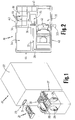
- the preparation of the films magazines (see fig. 2) is effected on a flat table 32 of parallelepiped form, disposed above the preparation station 27, of which it forms said movable access door 28 thereof, which in turn is provided on its upper surface with a plurality of suitably hollow and shaped seats 33,34,35,36,37,38, adapted to accomodate a magazine 21 for the films to be developed and all the required tools and materials for preparing such magazine 21 before introduction thereof into the opening 31 of the loading station 23 of the developing machine.
- the seat 33 for accomodation of the magazine 21 is realized of substantially rectangular shape and is provided preferably parallel and adjacent to the front edge 40 of the flat table 32, being extended practically for almost the entire lenght of the same table.
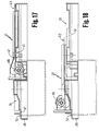
- such seat is provided with cavities having different shapes and depths, adapted to contain the correspondent magazine 21 at a rest condition thereof, in two different positions of such magazine during preparation thereof with the films to be developed, namely respectively a first position in which said magazine rests on the right side of the seat 33 (which position is indicated in the fig. 15-17) and a second position, in which said magazine is upset with respect to the preceding position and rests on the left side of the seat 33 (which position is indicated in the fig. 16-18).
- a cutter 41 or similar cutting tool which can be actuated by the lever 331 in order to be able to perform the functions hereinafter described, said cutter 41 being disposed in such a manner as to coincide with a correspondent through opening 42 of the overhanging magazine 21, when it rests on the seat 33 at the first operative position thereof (see fig. 15).
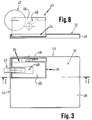
- the seat 34 is shaped preferably with rectangular form and is provided at the level of the back edge 43 and of the side left edge 44 of the flat table 32, in order to be able to accomodate at least a conventional tape dispenser 45 (see fig. 3-8) therein, which tape is of the kind normally used for connection of the films to be developed to the associated leader 63 and is adapted to withstand to the chemical treatment baths and to the drying temperatures during the different treatment steps of the same films while passing through the various stations of the developing machine.
- such tape dispenser comprises in a per se known manner a parallelepiped block 46 insertable into the seat 34, which carries a tape roll 47 horizontally pivoted and rotatably housed in a correspondent central cavity 48 thereof, as well as comprises a shaped arm 49 projected sidewise from said block, in order to be able to unroll and cut adequate predetermined portions of tape of the desired lenght with conventional manners, the assembly being of per se known kind.
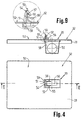
- the seat 35 is constituted by a parallelepiped cavity, parallelly adjacent to the seat 33 for accomodation of the magazine 21 and is provided with such a depth as to be able to accomodate a dispenser roll 50 therein for dispensing selfadhesive labels 59 for identification of each film, wherein such labels 59 are being adhering with a suitable glue means at regular intervals on a correspondent support band 58 and may be picked up separately therefrom for its use.
- such dispenser roll 50 is arranged inside the seat 35 and the band 501 may be gradually extracted therefrom through a correspondent adequately sized groove 51, provided on the flat upper surface 52 of the table 32 and defined by a vertical edge 53 connected to the flat upper surface 52 and provided with an inclined end corner 54 extended for the entire width of the same edge.
- such vertical edge 53 is laterally delimited by two adequately shaped side walls 55,56, identical and parallel to each other, projected vertically from the upper surface 52, between them a horizontal short shaft 57 disposed at a close spacing from the opposite surface of the vertical edge 53 is fixed, so as to define a slit into which the end of the band 58 for supporting labels 59 is inserted, which band has been passed in advance over the inclined end corner 54 in such a way that, when the support band 58 together with the associated labels 59 arrives at the level of the inclined end corner 54 of the vertical edge 53, where the feeding path thereof is inverted, the correspondent label 59 here arrived is authomatically detached from the same band 58 (see enlarged item of the fig. 9) and thus may be easily picked up therefrom and applied on the film to be identified.
- the seat 36 (see again fig. 2 and particularly fig. 5 and 10) is also constituted by a cavity of parallelepiped form and is provided near the previously described seat 35 being provided with such a depth as to be able to accomodate an extractor 361 of film tangs (of films of size 135) of per se known kind, from the associated magazines 21.
- the subsequent seat 37 is also constituted by a parallelepiped cavity and is provided at a position interposed between the seats 33 and 34.
- the scope of the seat 37 is to be able to accomodate a plurality of "leaders" 63 of conventional kind therein (see fig. 6 and 11), which are placed side by side and may be easily extracted therefrom for their normal use.
- the seat 38 is constituted by a cavity extended near the back edge 43 and the right hand side edge 65 of the flat table 32, which is provided internally with a plurality of vertical partition walls 66 parallel and orthogonally crossing to each other (see fig. 7 and 12), defining respective separated rooms for accomodation of correspondent containers 67 of the films to be developed, of per se known kind, which are so shaped and dimensioned as to be able to house films of any size.
- the introduction of films into the relevant container 67 is effected inside the lightproof station 27, by transferring the film from the relevant winding reel or roll to the container 67, which then is extracted from the station 27 and fitted to the magazine 21, so as to connect the relevant film to be developed to the correspondent "leader".
- films of any size may be introduced within the container 67, whose ends will be connected as described hereinafter to the correspondent ends of associated leaders, without danger of undesired exposures at the light thereof.
- the film magazine 21 is illustrated, it is constituted by a flat member 68 having parallelepiped form and reduced thickness, preferably obtained by joining reciprocally two separated half members made of plastic material in a per se known manner, said flat member 68 being made in one piece with a flat plate 69 arranged orthogonally thereto and forming the front side of the magazine 21.
- the two half members forming such flat member 68 are shaped with a curved profile convex at a transversal direction thereof, thus defining a longitudinal central opening 70 profiled in a correspondent way and connected laterally to two longitudinal grooves 71 and 72, adequately dimensioned to permit insertion of the leaders 63 therein.
- the flat member 68 is provided at a position contiguous to the front plate 69 with a space 73 in a transversal direction thereto, having a semi-circular profile on its lower part.
- Such space 73 is provided on the outer surfaces of its sides with two side flanges 681 which, as described later, will bear against the correspondent sprung pushing elements 121 and 122 when the magazine 21 is inserted in the opening 31 of the box-like casing 118, and furthermore is so dimensioned as to permit accomodation of a roll 116 for film of size 135 or, in the case of films of size other than that, of a container 67 therein, in which a correspondent film has been introduced in advance.
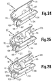
- the space 73 is provided at the sides of the semi-circular lower part thereof with two side projections 74 constituting two correspondent guide members, in which the side flanges 108-109 provided on the sides of the container 67 are engaged (see fig. 22-23-24-25-26).
- an adequately shaped pushing bar 76 is also provided, having a lenght which is larger than that of the same opening and whose ends are sliding in correspondent buttonholes provided along the longitudinal edges 78 and 79 opposite to each other of the flat member 68.
- pushing bar 76 has its ends engaged in two pushing springs 80,81 housed within correspondent guiding cavities and from at least one of said ends a projection 761 extends, adapted to engage the lever for operating microswitch 132 for the reasons set forth below.
- the pushing bar 76 is kept pushed toward the space 73 of the magazine 21 by the action of the pushing springs 80 and 81, so as to be pressed against either the possible roll 116 of a film of size 135 or the film container 67 which has been introduced into said space 73, by stopping it in this position.
- two side projections 211 are provided at the sides of said front edge 731, in front of said pushing bar 76, on which projections the side ears 111 of said container 67 are resting in the manner hereinafter described, when the container is inserted into the space 73.
- a lamina spring 86 or the like is provided inside this latter, which spring is fitted in a per se known manner to the surface of said flat plate 69, in the interior of the same space 73, said lamina spring 86 being adapted to push either the roll 116 or the film container 67, which are introduced between the same spring 86 and the pushing bar 76, in a direction opposite to that of this latter.
- said lamina spring 86 at the central part of its free end is shaped with a rectangular recess 117, so dimensioned as to be able to hold a roll 116 of a film of size 135, as clearly pointed out from fig. 21 and hereinafter described more in detail.
- the magazine 21 is provided with a movable closing door 90 which is shaped for being adapted above the space 73, so as to contain each roll 116 or container 67 introduced therein, said closing door 90 being provided in one piece with two thin side strips 91,92 pivoted at their respective free ends on correspondent seats 93,94, provided on the upper part of the flat member 68 along the transversal edge of the same through opening 42.
- such closing door 90 is provided with a movable contact element 95 housed within a correspondent seat provided on the underlying surface of the door 90 and fixed in position by per se known fixing means, so that to be able to be shifted with a short stroke perpendicularly to the flat surface of the same door.
- This contact element 95 is provided at its ends with two side projections 96 adapted to engage with their lower ends, at the position in which the door 90 is closed, the side flanges 108 and 109 of the film container 67 introduced in the same space 73, while as described hereinafter more in detail the inclined planes 961 provided on the front part of their upper ends engage correspondent inclined planes 313 provided on the extended box-like casing 118 of the loading station 23.
- the door 90 In order to be able to introduce into or extract either a roll 116 or a film container 67 from the space 73, the door 90 is being rotated around the associated hinge studs, thus causing the displacement from the closed position to the other opened position thereof (upset of about 180° with respect to the previous one), where it rests on the upper surface of the flat member 68.
- each roll 116 or film container 67 so positioned in the magazine 21 may be seized the free end of the film to be developed accomodated therein, which end is projecting therefrom, and this end is being passed over the pushing bar 76 through the central guide opening 87, provided between this bar and the door 90 of said film magazine 21, and after closure of such door 90 there are performed operations of the eventual cutting of the tang of films of size 135, of connection thereof to the leader 63 and of fitting of the identification label 59 thereto, as described hereinafter more in detail.
- the magazine 21 is provided with a plurality of through openings 97,98,99,100, arranged aligned transversally to each other and provided near the end of the flat member 68 in which the leader 63 is introduced.
- the scope of the through openings 97,98,99,100 is to permit to identify the size of film to be developed introduced in the magazine 21, by utilizing conventional photosensor elements such as reflection photodetectors or similar optoelectronic components disposed in positions corresponding to the same openings and provided on the developing machine as well as adequately connected to the electronic circuit thereof, in order to be able to determine authomatically the duration of the developing step and the regenerating step of the treatment baths depending on the kind of the identified film.
- conventional photosensor elements such as reflection photodetectors or similar optoelectronic components disposed in positions corresponding to the same openings and provided on the developing machine as well as adequately connected to the electronic circuit thereof, in order to be able to determine authomatically the duration of the developing step and the regenerating step of the treatment baths depending on the kind of the identified film.
- the photosensor A does not signal any presence and the photosensors B,C,D detect all the presence of diaphragm, the presence of films of size 120,220 or 620 is signaled.
- the photosensors B and C signal the presence of diaphragm, the presence of films of size 126 or 135 is signaled.
- the magazine 21 placed on the upper surface of the flat table 32 on the relevant seat 33 thereof and disposed in two different positions, to permit to connect the initial end of a film to be developed inserted into the space 73 to the associated leader 63, inserted in advance through the longitudinal opening 70 of the same magazine.
- the magazine 21 is provided by way of example with a roll 116 of a film of size 135.
- Such magazine 21 is firstly laid on the right hand side of the relevant seat 33 thereof, so that the closing door 90 is turned upwardly and the film is slightly extracted from its roll 116 upon extraction of its end tang, effected by means of a well known extraction device housed in the seat 36 of said flat table.
- such tang then is inserted in the opening 42, by penetrating vertically in the underlaying space, and a suitable portion of tape drawn from the relevant dispenser 45 is affixed on the ends of the film and of the leader adjacent to each other at the level of the through opening 42, thus obtaining the junction on such ends.
- the magazine 21 is moved to its other position, where it is upset with respect to the previous one as well as is introduced on the left hand side of the seat 33, as pointed out from fig. 16 and 19 and as previously, a further adequate portion of tape is affixed on the relevant outer surfaces of the film and of the leader, thus obtaining another reciprocal junction of these parts.
- the magazine 21 is ready for being inserted in the opening 31 of the loading station 23 of the film developing machine for developing such film in a conventional manner.
- the container 67 in which the film to be developed is housed is introduced in the space 73 of the magazine 21, by arranging it against the inclined part 101 of the lamina spring 86 which is joined to the vertical part 102 thereof, connected in a per se known manner to the inner surface of the front part 69 of the magazine 21, so that such container 67 is interposed between such lamina spring 86 and the pushing bar 76, which position it into said space 73.
- the container 67 is substantially constituted by two half-shells 104-110 interconnected to each other and more precisely by a first half-shell 104 formed by a semicylindrical casing frontally connected to a flat portion 106 and laterally closed by two circular diaphragms 107, each of which is provided outside two side flanges 108 and 109 vertical and spaced to each other, adapted to be inserted in the side projections 74 of the space 73 thus preventing the container 67 from rotating during unrolling of the film introduced therein.
- the container 67 is also constituted by a second half-shell 110 formed by a further semicylindric casing, which is hinged to the previous half-shell 104 along the line 105 providing an actual hinge, obtained simply by a correspondent reduced thickness of the casing of the preceding half-shell 104, so as to be able to be opened and closed.
- Two laterally projected ears 111 are also provided at the side ends of the front edge of said second half-shell 110, which ears are resting on the side projections 211 of the magazine 21 when said container 67 is introduced in the space 73 of the same magazine 21.
- Either a roll of a film of size 120 or, for other sizes of films, a shaped element as pointed out from fig. 25 and 26, may be introduced inside the cylindric cavity defined between said half-shells 104 and 110, which element is provided with two semicylindrical portions 112 and 113 suitably spaced to each other and reciprocally interconnected by another semicylindrical portion 114, in order to define a space therebetween, to accomodate the respective film to be developed (not shown).
- the adapter elements 103 of the fig. 25 and 26 have spaces with different width to accomodate correspondent films with different size and are also provided with a longitudinal rib 115, adapted to bear against the associated edge of the rectilinear portion 106 of the container 67, in order to prevent the adapter element 103 from being rotated undesiderately into its seat during unrolling of the film to be developed.
- fig. 25 illustrates an adapter for films of size 126
- fig. 26 illustrates an adapter for films of size 110.
- the inner walls of both the container 67 and the adapters which are in contact with the associated films are adequately coated with suitable soft protecting material, as for instance velvet or the like.
- the adapter elements 103 may be obviously obtained also with different shapes.
- fig. 21 shows the item of the assembly of a roll 116 for films of size 135 in the space 73 of the magazine 21.
- the container 67 isn't used and such roll 116 is directly introduced within the correspondent rectangular recess 117, provided centrally on the end of the inclined part 101 of the lamina spring 86, so as to be interposed as previously between said lamina spring and the pushing bar 76, being also prevented from being moved transversally thereto, in order to permit the relevant film to be unrolled from such roll.
- the so loaded container 67 then is closed thus keeping adequately protected the film at a dark ambient, like a film of different size.
- this container is extracted from said preparation station 27 and introduced in the space 73 of the magazine 21 and this latter, then, is put in correspondence of the preparation device 30, for performing junctions of the same film with the associated leader 63 in the previously described manners.
- the film to be developed is made of size 135 and then is contained within the correspondent roll 116, it isn't needed to transfer thereof in a container 67 on the above specified preparation station 27 and thus such roll may be directly introduced in the space 73 of the magazine 21, for performing the requested junctions with the associated leader as described.
- the movable door 90 is closed over either the container 67 or the roll 116 introduced into the space 73 of the magazine 21 and thus this latter is ready for being introduced in the side opening 31 of the loading station 23 of the machine.
- FIG. 27 is shown a perspective view of a so predisposed magazine 21 being about to be inserted in the correspondent opening 31 of the loading station 23 of the developing machine.
- the loading station 23 is substantially constituted by an extended box-like casing 118 which is adequately connected in a per se known manner inside the film developing machine and is formed by the reciprocal junction of two plate elements 119 and 120, adaptable at a superimposed position to each other.
- such plate elements 119 and 120 are so shaped as to define the opening 31 for introduction of the magazine 21 therebetween, which magazine 21 will penetrate about for half lenght thereof and afterwards to define a space provided with suitable entrainment units, formed in a per se known way by pairs of cylindrical rolls 145 and 146 appropriately interconnected to correspondent driving means of the developing machine, adapted to engage the leader and the film associated thereto for entrainment threof inside the same film developing machine.
- the box-like casing 18 is provided with two sprung pushing elements 121 and 122, protruding from a transversal vertical wall (not shown) located below the inner opening for introduction of the member 68 of the magazine 21, such sprung elements 121 and 122 being adapted to engage the side flanges 681 of the magazine 21, when this latter is fully introduced within said opening 31.
- such sprung pushing elements 121 and 122 are urged inwards by such side flanges 681, so as to tend to urge the magazine 21 fairly outwards at a slightly extracted position thereof with respect to the front surface of the box-like casing 118.
- the front ends of said projected elements 312 are beveled, thus providing actual inclined planes 313 which, as described later, engage the corresponding inclined planes 961 provided on the front part of the upper ends of the side projections 96 of the movable contact element 95.
- two flat walls 123,124 parallel and spaced to each other are extended vertically and perpendicularly below the lower wall 130 of the opening 31, which walls are made in one piece with the box-like casing 118 thus defining a central space in which an electro-magnet 127 oriented in vertical direction is housed, whose core terminates at its upper part with a sprung pin 128 urged upwards by the spring 129, passing through a correspondent hole provided on said lower wall 130 of the side opening 31.
- such sprung pin 128 is aligned with a correspondent hollow (not shown) provided on the magazine 21 and engaged by the en of such pin urged by said spring 129, so that when said magazine 21 is inserted in said box-like casing 118 the magazine 21 is locked by such pin and, on the contrary, is unlocked by the pin when the electromagnet is energized, thus making such magazine easily extractable from such casing 118 due to the pushing action outwards exerted by said sprung pushing elements 121 thereagainst.
- box-like casing 118 is provided laterally with two electric microswitches 131 and 132, spaced to each other and respectively actuatable by the end part of the flat member 68 of the magazine 21 and by the correspondent raised part 761 of the pushing bar 76 projected from the same magazine.
- the microswitches 131 and 132 are connected in series to each other in the electrical circuit of the developing machine and allow operation thereof solely when both are switched on, in which condition the magazine 21 is fully inserted in the opening 31 of the box-like casing 118, on the contrary by preventing operation thereof in the case in which the microswitch 132 only, which is accessible from outside, is actuated, thus providing an operation safety for the operator.
- a suitable electronic card thereon which card is substantially formed by a plate 133 provided with a set of photosensors (not shown), located at the level of the through openings 134, 135, 136 and 137 coinciding with the through openings 97,98,99 and 100 of said flat member 68, always when this latter is fully inserted in the box-like casing 118.
- Said photosensors are adapted to detect, in a per se known manner and as described later, the size of each film to be developed while sliding at the visual range of these components, and consequently to operate in a per se known way the regeneration of the various film treatment baths.
- the box-like casing 118 is provided with a cutter 138 connected at its lower part in a position coincident with the through opening 42 of the magazine 21, when this latter is fully introduced in the same casing, said cutter being adapted to cut the terminal end of the film of size 135 when this is fully extracted from the relevant roll inserted in the space 73 of said magazine 21.
- the cutter 138 is constituted by a blade 139 supported by a transversal plate 148 vertically slidable with a suitable stroke, which rests at its lower part on the movable core of the electromagnet 141 fitted to an associated casing 145 connected below the box-like casing 118.
- the transversal plate 148 is slidably guided by two side guiding studs 146-147 engaging the side bushes thereof and is pushed downward by pushing springs 143-144, so as to position such blade 139 on its rest position, in which it is retracted and doesn't act against the film.
- the electromagnet 141 is connected to the electric circuit of the machine and is energized only at the end of unrolling of the films of size 135, so that the movable core thereof is pushed upwards, against the action of springs 143 and 144 which are compressed, and the blade 139 abuts on the film thus providing cutting of the terminal end thereof.
- the cutter 138 is operated only when on the magazine 21 is fitted a normal roll for films of size 135 in which, as known, the film is connected to the associated reel.
- this latter abuts with the raised part 761 on the control lever of the microswitch 132, by switching on thereof, so that due to the fact that the microswitch 131 too is switched on, since the magazine 21 is positioned on the box-like casing 118, the cutter 128 is operated in actuation and then cuts the terminal end of the film, which film is thus detached from the associated reel and may continue regularly to be entrained inside the film developing machine.
- the box-like casing 118 is provided with two pairs of cylindric rolls 145 and 146 placed side by side and rotating in opposite directions to each other, which rolls, as already specified, are rotatably driven by per se known driving members and are situated along the box-like casing 118, wherein at the middle part thereof comprised between the zone of the plate 133 and the end provided inside the film developing machine 20 the two rolls of each pair of cylindric rolls 145-146 are pushed reciprocally the one against the other one by suitable side springs, so as to cause the frictional entrainment of the leaders and of the films connected thereto and the subsequent transfer threof toward the chemical treatment baths and the drying zone of the developing machine (not shown).
- the magazine 21 provides for switching on the microswitch 131 thus signalling the presence of the magazine 21 to the microproccessor which controls operation of the machine.
- the operation starting of the machine depends also, as already stated, by the presence of the leader in the magazine which is detected by the associated photodetector A and operation thereof may proceed depending on the state detected by the photodetector elements, whose arrangement practically define, as already stated, the kind of film being passing through the machine and the transit time thereof, so that the microprocessor included in the machine provides for regulating and controlling accordingly all the operations involved, in particular depending on the size and the lenght of the treated films the regenerations of the various chemical treatment baths will be adequately adjusted.
- the microprocessor provides for controlling the continuation of the needed operations in course and at the same time the electromagnet 127 is energized, which causes attraction of the sprung pin 128 by bringing it out of the recess of the magazine 21 where such pin was penetrated, so that this magazine 21 is disengaged from the box-like casing 118 and the action of the two sprung pushing elements 121 and 122 pushes it slightly outwards, thus the magazine 21 may be seized by the operator and extracted from the box-like casing 118.
- the machine obviously stops it authomatically at the end of the various treatment steps of the film, unless another magazine in the meantime has been inserted in its loading station.
- the arrangement of films in the associated magazines, their joining to the respective leaders and the displacement of the so prepared magazines from the preparation station to the loading station may be effected in a rational, easy and safe manner, especially dangers of slipping of films out from the associated containers during transfers thereof are avoided.
- the presence of the containers and of the adapter elements permits to develop not only films with size 1:35 but also films with different sizes, by utilizing magazines of the kind referred to which clearly are simple in construction and adapted to permit introduction of films in the conventional developing machines in a safe, simple and reliable way as well as in case in a fully authomatic way too.
- the loading station of the film developing machine could be provided advantageously with a suitable authomatic loading device, adapted to feed authomatically in a continuous succession a unit of magazines of the kind referred to.
- the magazines could be disposed circumferentially on a suitable circular support, which authomatically position them Just at the level of the loading station where an appropriate kinematic device controls also authomatically switching on and off thereof, the assembly will be obviously connected to and controlled by the film developing machine to which the device is fitted.
Landscapes
- Physics & Mathematics (AREA)
- General Physics & Mathematics (AREA)
- Photographic Developing Apparatuses (AREA)
- Sheets, Magazines, And Separation Thereof (AREA)
- Photographic Processing Devices Using Wet Methods (AREA)
Claims (14)
- Développeuse pour films de différentes tailles comprises entre les tailles 110 et 620, comprenant une station de préparation (27) dans laquelle chaque film qui est à développer est associé à au moins un guide (63) de type conventionnel, une station de traitement constituée d'une série de bacs contenant les différents bains de traitements chimiques, une station de chargement (23) fournie avec des paires de rouleaux cylindriques (145, 146) ou pièces similaires soumis aux moyens de contrôle (131, 132), pour l'entraînement desdits films dans ladite station de traitement, un chargeur (21) dans lequel lesdits films et lesdits guides (63) sont incorporés et joints ensemble avant l'introduction dudit chargeur (21) dans ladite station de chargement (23), et une station de séchage pour sécher les films développés, où dans ladite station de préparation (27) sont incorporés différents boîtiers (67) dans lesquels les films de différentes tailles, une pluralité de guides (63) et accessoires (47) pour relier chaque film au guide associé (63), aussi bien que des accessoires (59) pour l'identification de chaque film peuvent être insérés, ladite station de préparation (27) étant aussi adaptée pour incorporer ledit chargeur (21), caractérisé en ce que ledit chargeur (21) comprend une partie plate allongée (68) fixée perpendiculairement à une plaque (69), ladite partie plate (68) comprenant un logement transversal (73) pour y recevoir chaque film, ce film étant soit enroulé sur son propre rouleau (116) ou introduit dans un desdits boîtiers (67), ce logement est fermé par une trappe de fermeture amovible correspondante (90) fixée par des charnières sur ladite partie plate (68), ladite partie plate (68) comprenant aussi une ouverture centrale longitudinale (70) pour l'introduction dudit guide (63) à l'intérieur, et pour laisser passer ledit film dudit logement (73) à la station de traitement, une lumière (42) pour permettre l'assemblage du film au guide, aussi bien que d'autres lumières (97 - 100) coïncidant avec les composants optoélectroniques tels que cellules photoélectriques, diodes photoélectriques ou équivalents installés dans la station de chargement et adaptés pour vérifier la taille de chaque film à développer.
- Développeuse pour films selon la revendication 1, se caractérise en ce que ledit logement (73), pour l'introduction dudit boîtier (67) à l'intérieur, comprend deux butées latérales séparées l'une de l'autre ainsi qu'un premier et un second élément à ressort (76, 86) espacés et agissant en opposition l'un par rapport à l'autre, dans un sens longitudinal par rapport à ladite pièce plate (68), ledit boîtier (67) étant placé entre ces éléments à ressort ( 76, 86).
- Développeuse de films selon la revendication 2, se caractérise en ce que ledit premier élément à ressort comporte une tige de poussage de forme adéquate (76), disposée transversalement par rapport à ladite pièce plate (68), dont les extrémités coulissent à la suite d'un courte poussée dans le sens longitudinal de ladite pièce plate (68) dans les trous correspondants (77) situés sur les bords longitudinaux (78, 76) de la même plaque, à l'intérieur desquels les extrémités de la tige (76) sont poussées par les ressorts poussoirs respectifs (80, 81) vers ledit logement (73).
- Développeuse pour films selon la revendication 3, se caractérise en ce que le dit élément à ressort est constitué par une ressort à lame (86), formé d'une partie verticale (102) fixée d'une certaine manière à la surface intérieure dudit logement (73) et d'une partie inclinée (101).
- Développeuse pour films selon la revendication 4, se caractérise en ce que ladite partie inclinée (101) du ressort plat (86) comporte un espace central (117) pour y recevoir chaque rouleau de film (116).
- Développeuse pour films selon la revendication 5, se caractérise en ce que ledit boîtier (67) est formé d'une première et d'une seconde semi-coquilles (104, 110) respectivement articulées et encastrables, pour contenir au moins un élément adaptateur (103) prévu pour permettre l'insertion de films de différentes tailles, ladite première demi-coquille (104) comprenant sur les côtés des saillies longitudinales (108, 109) qui peuvent s'engager dans lesdites projections (74) dudit logement (73) du chargeur (21).
- Développeuse pour films selon la revendication 6, ce caractérise en ce que ledit élément adaptateur (103) comporte deux portions de surface semi-cylindrique (112, 113), écartées réciproquement et réunies ensemble par une autre portion de surface semi-cylindrique (114) opposée aux précédentes pour former le siège de réception du film qui doit être développé.
- Développeuse pour films selon la revendication 7, se caractérise en ce que lesdites deux portions de surface semi-cylindrique (112, 113) comportent une saillie longitudinale (115), prévue pour s'appuyer contre le bord longitudinal correspondant de ladite première demi-coquille (104) du logement (67), pour empêcher ledit élément adaptateur (103) de tourner pendant le débobinage du film qu'il contient.
- Développeuse pour films selon la revendication 8, se caractérise en ce que les surfaces intérieures desdites première et seconde demi-coquilles (104, 110) sont recouvertes d'un matériau de protection doux en velours ou autre.
- Développeuse pour films selon la revendication 9, se caractérise en ce que ladite trappe amovible de fermeture (90) comporte, sur sa surface tournée soit vers ledit rouleau (116) ou ledit logement (67) un élément de contact mobile (95) coulissant sous une courte poussée vers l'emplacement correspondant (96) et adapté pour reposer ou sur ledit rouleau (116) ou sur le dit boîtier (67), dans la position dans laquelle ladite porte amovible (90) est fermée sur le logement (73) du chargeur (21).
- Développeuse pour films selon la revendication 10, se caractérise en ce que lesdits moyens de contrôle comprennent lesdits composants optoélectroniques, au moins un premier et un second micro-interrupteurs électriques (131 132) ou équivalents qui peuvent être fermés respectivement par la présence de l'extrémité de ladite pièce plate (68) dudit chargeur (21) et par ladite tige poussoir (76), au moins une clavette (128) adaptée pour tenir ledit chargeur (21) en position dans ladite station de chargement (23) contre l'action desdits éléments poussoirs (121, 122) ayant tendance à extirper légèrement ledit chargeur (21) de ladite station de chargement (23), et comprend également des moyens de coupe tels qu'un cutter ou équivalents adaptés pour sectionner la partie finale de chaque film, lesdits premier et second micro-interrupteurs (131 132) étant adaptés pour assurer, quand ils sont tous les deux fermés, le fonctionnement desdits rouleaux cylindriques (145, 146), desdits composants optoélectroniques et de tenir ledit chargeur (21) en position au moyen de ladite clavette et étant adaptés pour assurer l'ouverture des interrupteurs desdits rouleaux cylindriques (145, 146) et desdits composants optoélectroniques ainsi que l'extraction dudit chargeur (21) de ladite station de chargement (23), sous l'action desdits éléments poussoirs à ressort (121, 122) quand au moins un desdits micro-interrupteurs (131, 132) est ouvert, après l'activation dudit cutter (138) durant les étapes de l'opération de coupage dudit film.
- Développeuse pour films selon la revendication 11, se caractérise en ce que ladite clavette (128) est poussée verticalement vers le haut par un ressort (129), afin de pouvoir s'engager dans le logement correspondant dudit chargeur (21) pour le maintenir en place dans ladite station de chargement (23), ladite clavette (128) étant aussi actionnée pour se désengager dudit logement de ladite station de chargement (23) quand l'électro-aimant correspondant (127) est mis sous tension.
- Développeuse pour films selon la revendication 12, se caractérise en ce que ledit cutter (138) comporte une lame coulissant verticalement (139), fonctionnement simultanément avec le noyau d'un électro-aimant (141) logé dans un boîtier associé (142) placé sur ladite station de chargement (23), ladite lame (139) étant activée par le noyau dudit électro-aimant (141) de la position inférieure où elle est inactive, quand l'électro-aimant (141) est hors tension à la position supérieure de coupe quand ledit électro-aimant (141) est sous tension.
- Développeuse pour films selon la revendication 1, se caractérise en ce que ladite station de préparation (27) comprend un plateau supérieur (32) comprenant les supports (33, 34 35 37, 38) de forme adéquate et adaptée pour recevoir respectivement ledit chargeur (21) et les accessoires joints (47), ledit matériel d'identification (59), lesdits guides (63) et lesdits boîtiers (67), ledit support (33) pour ledit chargeur (21) ayant une forme adaptée pour recevoir l'ensemble dans deux positions différentes, face à face pour joindre les deux surfaces de chaque film à chaque guide (63), les moyens de coupage (41) étant disposés au niveau desdits supports (33) pour couper le bout du début de chaque film avant sa jonction au guide associé (63).
Applications Claiming Priority (2)
| Application Number | Priority Date | Filing Date | Title |
|---|---|---|---|
| IT45803A IT1238633B (it) | 1989-12-28 | 1989-12-28 | Caricatore di film per alimentare macchine sviluppatrici-film e dispositivo di preparazione di detto caricatore |
| IT4580389 | 1989-12-28 |
Publications (2)
| Publication Number | Publication Date |
|---|---|
| EP0437814A1 EP0437814A1 (fr) | 1991-07-24 |
| EP0437814B1 true EP0437814B1 (fr) | 1996-04-10 |
Family
ID=11258182
Family Applications (1)
| Application Number | Title | Priority Date | Filing Date |
|---|---|---|---|
| EP90125225A Expired - Lifetime EP0437814B1 (fr) | 1989-12-28 | 1990-12-21 | Magasin de film pour l'alimentation d'une machine de développement de film et dispositif de préparation d'un tel magasin |
Country Status (4)
| Country | Link |
|---|---|
| US (1) | US5311232A (fr) |
| EP (1) | EP0437814B1 (fr) |
| DE (1) | DE69026489T2 (fr) |
| IT (1) | IT1238633B (fr) |
Families Citing this family (7)
| Publication number | Priority date | Publication date | Assignee | Title |
|---|---|---|---|---|
| JP2830968B2 (ja) * | 1993-04-15 | 1998-12-02 | ノーリツ鋼機株式会社 | リーダ、該リーダとフィルムの接続および分離方法、ならびに自動リーダ着脱式現像装置 |
| JP3129879B2 (ja) * | 1993-06-03 | 2001-01-31 | ノーリツ鋼機株式会社 | 感光材料処理装置 |
| IT1265563B1 (it) * | 1993-06-16 | 1996-11-22 | San Marco Imaging Srl | Dispositivo di caricamento automatico di pellicole fotografiche per macchine sviluppatrici |
| EP0652479B1 (fr) * | 1993-11-08 | 1999-11-24 | Gretag Imaging Ag | Système de traitement photographique intégré et méthode pour son fonctionnement |
| JP2800676B2 (ja) * | 1994-04-25 | 1998-09-21 | ノーリツ鋼機株式会社 | スプライス台 |
| EP0877290B1 (fr) * | 1997-05-06 | 2004-10-13 | Gretag Imaging Ag | Dispositif de stockage et de transfert de matériau d'essai |
| US6040891A (en) * | 1997-05-14 | 2000-03-21 | Konica Corporation | Photographic printing apparatus |
Family Cites Families (4)
| Publication number | Priority date | Publication date | Assignee | Title |
|---|---|---|---|---|
| US3568587A (en) * | 1968-07-26 | 1971-03-09 | Jerome D Laval | Photographic paper feeding attachment for processor |
| DE3568225D1 (en) * | 1984-03-13 | 1989-03-16 | Fuji Photo Film Co Ltd | Developing apparatus |
| US4860044A (en) * | 1985-09-30 | 1989-08-22 | Konishiroku Photo Industry Co., Ltd. | Photographic material processing unit |
| DE242817T1 (de) * | 1986-04-18 | 1988-03-17 | Filmzufuehrvorrichtung. |
-
1989
- 1989-12-28 IT IT45803A patent/IT1238633B/it active IP Right Grant
-
1990
- 1990-12-21 DE DE69026489T patent/DE69026489T2/de not_active Expired - Fee Related
- 1990-12-21 EP EP90125225A patent/EP0437814B1/fr not_active Expired - Lifetime
- 1990-12-28 US US07/635,704 patent/US5311232A/en not_active Expired - Fee Related
Also Published As
| Publication number | Publication date |
|---|---|
| DE69026489D1 (de) | 1996-05-15 |
| IT8945803A1 (it) | 1991-06-28 |
| IT1238633B (it) | 1993-08-31 |
| DE69026489T2 (de) | 1996-12-05 |
| US5311232A (en) | 1994-05-10 |
| EP0437814A1 (fr) | 1991-07-24 |
| IT8945803A0 (it) | 1989-12-28 |
Similar Documents
| Publication | Publication Date | Title |
|---|---|---|
| EP0236904B1 (fr) | Réservoir alimenté par un film à rayons X, utilisable dans un appareil à traitement de film automatique | |
| EP0437814A1 (fr) | Magasin de film pour l'alimentation d'une machine de développement de film et dispositif de préparation d'un tel magasin | |
| US3957567A (en) | Splicing apparatus | |
| US4543771A (en) | Photographic slide mounter | |
| EP0101137B1 (fr) | Appareil à découper le pain | |
| KR100301592B1 (ko) | 전동테이프커터에있어서의안전장치 | |
| US3136678A (en) | Film splicer | |
| WO1994014661A1 (fr) | Appareil pour faire rentrer un article dans une housse | |
| JPS60194454A (ja) | 現像装置用フイルム集積装置 | |
| US4486262A (en) | Cassette loading machine | |
| US4117753A (en) | Sheet cutting apparatus | |
| ITPN930040A1 (it) | Dispositivo di caricamento automatico di pellicole fotografiche per macchine sviluppatrici | |
| US5250974A (en) | Apparatus for supplying a film for use in an automatic developing machine | |
| US5459538A (en) | Photo mounting equipment | |
| US3574037A (en) | Ultrasonic splicer | |
| JP2890014B2 (ja) | 磁気テープ巻取装置 | |
| GB2299563A (en) | Stowing umbrellas into sacks | |
| US3553056A (en) | Strip splicing device | |
| EP0360823B1 (fr) | Dispositif pour ouvrir et fermer une cassette de film en feuilles | |
| JP3364564B2 (ja) | カード発行装置の動作制御方法 | |
| US20020066991A1 (en) | Selective tag applicator | |
| JPH03277317A (ja) | 収納庫 | |
| JPH028291Y2 (fr) | ||
| BR102023018806A2 (pt) | Máquina de lacramento de embalagens para delivery | |
| EP0562677B1 (fr) | Appareil de développement photographique |
Legal Events
| Date | Code | Title | Description |
|---|---|---|---|
| PUAI | Public reference made under article 153(3) epc to a published international application that has entered the european phase |
Free format text: ORIGINAL CODE: 0009012 |
|
| AK | Designated contracting states |
Kind code of ref document: A1 Designated state(s): CH DE FR GB IT LI |
|
| 17P | Request for examination filed |
Effective date: 19920124 |
|
| 17Q | First examination report despatched |
Effective date: 19930805 |
|
| RAP1 | Party data changed (applicant data changed or rights of an application transferred) |
Owner name: SAN MARCO IMAGING S.R.L. |
|
| GRAA | (expected) grant |
Free format text: ORIGINAL CODE: 0009210 |
|
| AK | Designated contracting states |
Kind code of ref document: B1 Designated state(s): CH DE FR GB IT LI |
|
| PG25 | Lapsed in a contracting state [announced via postgrant information from national office to epo] |
Ref country code: IT Free format text: LAPSE BECAUSE OF FAILURE TO SUBMIT A TRANSLATION OF THE DESCRIPTION OR TO PAY THE FEE WITHIN THE PRE;WARNING: LAPSES OF ITALIAN PATENTS WITH EFFECTIVE DATE BEFORE 2007 MAY HAVE OCCURRED AT ANY TIME BEFORE 2007. THE CORRECT EFFECTIVE DATE MAY BE DIFFERENT FROM THE ONE RECORDED.SCRIBED TIME-LIMIT Effective date: 19960410 Ref country code: LI Effective date: 19960410 Ref country code: CH Effective date: 19960410 |
|
| REF | Corresponds to: |
Ref document number: 69026489 Country of ref document: DE Date of ref document: 19960515 |
|
| ET | Fr: translation filed | ||
| REG | Reference to a national code |
Ref country code: CH Ref legal event code: PL |
|
| PLBE | No opposition filed within time limit |
Free format text: ORIGINAL CODE: 0009261 |
|
| STAA | Information on the status of an ep patent application or granted ep patent |
Free format text: STATUS: NO OPPOSITION FILED WITHIN TIME LIMIT |
|
| 26N | No opposition filed | ||
| REG | Reference to a national code |
Ref country code: GB Ref legal event code: 732E |
|
| REG | Reference to a national code |
Ref country code: FR Ref legal event code: GC |
|
| REG | Reference to a national code |
Ref country code: GB Ref legal event code: IF02 |
|
| PGFP | Annual fee paid to national office [announced via postgrant information from national office to epo] |
Ref country code: DE Payment date: 20030213 Year of fee payment: 13 |
|
| PG25 | Lapsed in a contracting state [announced via postgrant information from national office to epo] |
Ref country code: DE Free format text: LAPSE BECAUSE OF NON-PAYMENT OF DUE FEES Effective date: 20040701 |
|
| PGFP | Annual fee paid to national office [announced via postgrant information from national office to epo] |
Ref country code: FR Payment date: 20041231 Year of fee payment: 15 |
|
| PGFP | Annual fee paid to national office [announced via postgrant information from national office to epo] |
Ref country code: GB Payment date: 20050119 Year of fee payment: 15 |
|
| PG25 | Lapsed in a contracting state [announced via postgrant information from national office to epo] |
Ref country code: GB Free format text: LAPSE BECAUSE OF NON-PAYMENT OF DUE FEES Effective date: 20051221 |
|
| GBPC | Gb: european patent ceased through non-payment of renewal fee |
Effective date: 20051221 |
|
| PG25 | Lapsed in a contracting state [announced via postgrant information from national office to epo] |
Ref country code: FR Free format text: LAPSE BECAUSE OF NON-PAYMENT OF DUE FEES Effective date: 20060831 |
|
| REG | Reference to a national code |
Ref country code: FR Ref legal event code: ST Effective date: 20060831 |