EP0437772A1 - Boiling liquid cooling system for a liquid cooled internal combustion engine - Google Patents
Boiling liquid cooling system for a liquid cooled internal combustion engine Download PDFInfo
- Publication number
- EP0437772A1 EP0437772A1 EP90124708A EP90124708A EP0437772A1 EP 0437772 A1 EP0437772 A1 EP 0437772A1 EP 90124708 A EP90124708 A EP 90124708A EP 90124708 A EP90124708 A EP 90124708A EP 0437772 A1 EP0437772 A1 EP 0437772A1
- Authority
- EP
- European Patent Office
- Prior art keywords
- cooling system
- evaporative cooling
- coolant
- space
- compensation
- Prior art date
- Legal status (The legal status is an assumption and is not a legal conclusion. Google has not performed a legal analysis and makes no representation as to the accuracy of the status listed.)
- Granted
Links
Images
Classifications
-
- F—MECHANICAL ENGINEERING; LIGHTING; HEATING; WEAPONS; BLASTING
- F01—MACHINES OR ENGINES IN GENERAL; ENGINE PLANTS IN GENERAL; STEAM ENGINES
- F01P—COOLING OF MACHINES OR ENGINES IN GENERAL; COOLING OF INTERNAL-COMBUSTION ENGINES
- F01P3/00—Liquid cooling
- F01P3/22—Liquid cooling characterised by evaporation and condensation of coolant in closed cycles; characterised by the coolant reaching higher temperatures than normal atmospheric boiling-point
- F01P3/2271—Closed cycles with separator and liquid return
-
- F—MECHANICAL ENGINEERING; LIGHTING; HEATING; WEAPONS; BLASTING
- F01—MACHINES OR ENGINES IN GENERAL; ENGINE PLANTS IN GENERAL; STEAM ENGINES
- F01P—COOLING OF MACHINES OR ENGINES IN GENERAL; COOLING OF INTERNAL-COMBUSTION ENGINES
- F01P11/00—Component parts, details, or accessories not provided for in, or of interest apart from, groups F01P1/00 - F01P9/00
- F01P11/02—Liquid-coolant filling, overflow, venting, or draining devices
-
- F—MECHANICAL ENGINEERING; LIGHTING; HEATING; WEAPONS; BLASTING
- F01—MACHINES OR ENGINES IN GENERAL; ENGINE PLANTS IN GENERAL; STEAM ENGINES
- F01P—COOLING OF MACHINES OR ENGINES IN GENERAL; COOLING OF INTERNAL-COMBUSTION ENGINES
- F01P11/00—Component parts, details, or accessories not provided for in, or of interest apart from, groups F01P1/00 - F01P9/00
- F01P11/14—Indicating devices; Other safety devices
- F01P11/16—Indicating devices; Other safety devices concerning coolant temperature
-
- F—MECHANICAL ENGINEERING; LIGHTING; HEATING; WEAPONS; BLASTING
- F01—MACHINES OR ENGINES IN GENERAL; ENGINE PLANTS IN GENERAL; STEAM ENGINES
- F01P—COOLING OF MACHINES OR ENGINES IN GENERAL; COOLING OF INTERNAL-COMBUSTION ENGINES
- F01P11/00—Component parts, details, or accessories not provided for in, or of interest apart from, groups F01P1/00 - F01P9/00
- F01P11/14—Indicating devices; Other safety devices
- F01P11/18—Indicating devices; Other safety devices concerning coolant pressure, coolant flow, or liquid-coolant level
-
- F—MECHANICAL ENGINEERING; LIGHTING; HEATING; WEAPONS; BLASTING
- F01—MACHINES OR ENGINES IN GENERAL; ENGINE PLANTS IN GENERAL; STEAM ENGINES
- F01P—COOLING OF MACHINES OR ENGINES IN GENERAL; COOLING OF INTERNAL-COMBUSTION ENGINES
- F01P11/00—Component parts, details, or accessories not provided for in, or of interest apart from, groups F01P1/00 - F01P9/00
- F01P11/02—Liquid-coolant filling, overflow, venting, or draining devices
- F01P11/0285—Venting devices
-
- F—MECHANICAL ENGINEERING; LIGHTING; HEATING; WEAPONS; BLASTING
- F01—MACHINES OR ENGINES IN GENERAL; ENGINE PLANTS IN GENERAL; STEAM ENGINES
- F01P—COOLING OF MACHINES OR ENGINES IN GENERAL; COOLING OF INTERNAL-COMBUSTION ENGINES
- F01P11/00—Component parts, details, or accessories not provided for in, or of interest apart from, groups F01P1/00 - F01P9/00
- F01P11/02—Liquid-coolant filling, overflow, venting, or draining devices
- F01P11/0204—Filling
- F01P11/0209—Closure caps
- F01P2011/0271—Semi-permeable, e.g. using Gore-Tex c fibres
-
- F—MECHANICAL ENGINEERING; LIGHTING; HEATING; WEAPONS; BLASTING
- F01—MACHINES OR ENGINES IN GENERAL; ENGINE PLANTS IN GENERAL; STEAM ENGINES
- F01P—COOLING OF MACHINES OR ENGINES IN GENERAL; COOLING OF INTERNAL-COMBUSTION ENGINES
- F01P2025/00—Measuring
- F01P2025/08—Temperature
-
- F—MECHANICAL ENGINEERING; LIGHTING; HEATING; WEAPONS; BLASTING
- F01—MACHINES OR ENGINES IN GENERAL; ENGINE PLANTS IN GENERAL; STEAM ENGINES
- F01P—COOLING OF MACHINES OR ENGINES IN GENERAL; COOLING OF INTERNAL-COMBUSTION ENGINES
- F01P2060/00—Cooling circuits using auxiliaries
- F01P2060/08—Cabin heater
Definitions
- the invention relates to a device of the type specified in the preamble of the first claim.
- An evaporative cooling system of the generic type is known from Motortechnische Zeitschrift (MTZ) No. 50 (1989), number 9, page 428.
- This cooling system has the advantage that an increased operating temperature can be achieved at partial load, but that the same efficiencies as a conventional cooling system can be achieved at high loads.
- the object of the present invention is to develop a generic evaporative cooling system in such a way that the additional space for an expansion tank can be dispensed with.
- this object is achieved by the characterizing features of the first claim.
- the solution is based on the basic idea that the cooling system is connected to the atmosphere depending on the temperature. The connection to the atmosphere is maintained as long as it is ensured that no steam can escape. If steam were to escape, this would mean a loss of liquid and thus a correspondingly increased liquid supply or a constant refilling of coolant. Both are prevented by the proposal according to the invention. Thus, even when the hot cooling system cools down and thus falls below a minimum temperature, the cooling system can be connected to the atmosphere again. This prevents negative pressure from developing in the cooling system.
- Claim 2 specifies a simple possibility of how the temperature-dependent ventilation can be carried out with little expenditure on equipment.
- the thermostatic valve is made of bimetal, for example.
- the development according to claim 3 ensures that air can escape and that water is retained.
- the air exchange itself takes place with the help of the pressure difference between the atmosphere and the cooling system on the molecular sieve.
- the development according to claim 4 ensures that a filling opening is created at the same time, which corresponds to the lid in conventional cooling systems using cooling liquid as the heat transfer medium. This eliminates the need for a separate filler opening for the coolant.
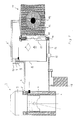
- Fig. 1 the schematic of the evaporative cooling according to the invention is shown schematically.
- the cylinder 1 and the cylinder head 2 of an engine 3, which is not otherwise shown in detail, are provided with cooling channels 4 and 5 or cooling chambers.
- a flow line 6 branches off.
- a steam separator 7 is installed in this flow line 6.
- the steam separator 7 is divided into a lower space 9 and an upper space 10 by means of an overflow line 8.
- the flow line 6 runs from the upper space 10 to a heat exchanger 11 working as a condenser.
- This heat exchanger 11 has a coolant collecting space 12 in its lower region.
- An equalization chamber 13 has a condensate reservoir 14 in the lower region. This is connected via a line 15 to the cooling water collecting space 12. Furthermore, the overflow line 8 opens into the storage space 14.
- the return line 16 leads from the storage space 14 with the interposition of a condensate pump 17 and a heating heat exchanger 18 back into the cylinder 1.
- the heating heat exchanger 18 is used to heat a passenger compartment of a vehicle driven by the internal combustion engine 3.
- the cooling capacity of the heat exchanger 11 can be increased by means of a blower 19 which sucks in cooling air and presses it through the heat exchanger 11.
- the upper space 10 of the steam separator and the part 6 'of the flow line 6 and the heat exchanger 11 and the compensation space 13 are filled with air in the cold state of the internal combustion engine 3, and with coolant vapor in the hot state.
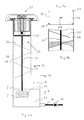
- the compensation space 13 is shown in more detail in FIG. 2. It is essentially tubular and has a closure cover 20 at its upper end.
- the coolant supply 21 In its lower area, it has a coolant supply 21 due to the connecting line 15.
- the level of the coolant supply depends on the temperature. It is at level I when the coolant is cold and at level II when the coolant is warm.
- the fill level indicator 22 serves to control the coolant level. It consists of a float 23 floating at the current coolant level, which is connected via a connecting rod 24 to a viewing plate 25 in the area of the cover 20.
- a separating labyrinth is formed below the cover 20 in the compensation space 13.
- This consists of sloping sheets 26 which are alternately attached to the wall of the compensation space 13. These sheets are - as Fig. 2c shows - provided at their highest points with compensating holes 27. Furthermore, they have an essentially centrally arranged bore 28 for the passage of the connecting rod 24.
- the slanted plates 26 have the task of liquid coolant, which u. U. is entrained by the air flowing to the cover 20 to separate.
- the compensating holes 27 cause here that no air cushion can hold under the sloping sheets. Therefore, these compensating holes 27 are provided at the highest point of the sheets.
- the passage 29 at the lower free end of the sheets 26 ensures that the separated coolant can flow off unhindered and that it is not closed by capillary action of the venting cross sections.
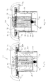
- the closure cover 20 is shown in more detail in FIG. 3. It consists essentially of a handle part 30 which is firmly connected to an insert 31.
- a temperature-controlled vent valve 32 as well as a molecular sieve 33 and a cover plate 34 are arranged in the insert 31.
- the vent valve 32 and the molecular sieve 33 form a structural unit which are arranged in the housing 35.
- the vent valve 32 which operates in a temperature-dependent manner - for example via a bimetal - is arranged at the inlet of the housing 35.
- the molecular sieve 33 is constructed in the manner of a cartridge and divides the housing 35 into a separating space 36 and a coolant-free space 37.
- the space 37 communicates with the space enclosed by the handle part 30 and the insert 31 via vent holes 38 in the cover plate 34. From there, holes 39 lead to the atmosphere.
- the cover plate 34 is supported by a spring 40 on the inside of the handle part 30. With the interposition of a seal 41, the cover plate 34 rests on the insert 31. The seal 41 is arranged so that the holes 39 always remain open. In this way, the cover plate 34 forms a spring-loaded pressure relief valve.
- the function of the compensation space 13 constructed according to the invention is explained in more detail below.
- the vent valve 32 is opened. This creates a flow connection to the atmosphere via the ventilation valve 32, the separating space 36, the molecular sieve 33, the space 37, the ventilation holes 38 and the holes 39. This is shown in FIG. 3a.
- the water Due to the inclined plates 26 and the bores 27 and the distance 29, the water is separated and only the steam reaches the vent valve 32. From there, the coolant vapor flows to the atmosphere in the same way as before. However, the coolant liquid contained in the coolant vapor is retained by the molecular sieve.
- the molecular sieve has the task of letting air escape and retaining water. The air is exchanged via the sieve with the help of the pressure difference between the atmosphere and the interior of the cooling system. The separated liquid coolant then runs back to the coolant storage space on the inclined plates.
- the vent valve 32 closes. This prevents vaporous coolant from escaping during operation and the liquid level within the cooling system thus drops.
- the ventilation valve 32 gradually cools down. At a temperature of around 80 ° C, for example, it opens again. This creates a connection between the cooling system and the atmosphere.
- Cooling creates a lower vacuum in the cooling system. This leads to the fact that the molecular sieve 33 again allows air to flow into the separating space 13 and the previously steam-filled spaces. The air exchange is completed when the pressure between the atmosphere and the cooling system is equalized.
- the entire cover 20 is removed. Now coolant can be poured in through the separation chamber and the inclined plates. The height of the coolant level is indicated by the viewing plate 25. Then the compensation chamber 13 is closed again with the cover 20. The cooling system is then ready for use.
Abstract
Description
Die Erfindung bezieht sich auf eine Vorrichtung der im Oberbegriff des ersten Anspruchs angegebenen Art.The invention relates to a device of the type specified in the preamble of the first claim.
Aus der Motortechnischen Zeitschrift (MTZ) Nr. 50 (1989), Heft 9, Seite 428, ist ein Verdampfungskühlsystem der gattungsgemäßen Art bekannt. Dieses Kühlsystem hat den Vorteil, daß eine erhöhte Betriebstemperatur bei Teillast realisiert werden kann, daß aber bei hoher Last die gleichen Wirkungsgrade wie ein konventionelles Kühlsystem erreicht werden.An evaporative cooling system of the generic type is known from Motortechnische Zeitschrift (MTZ) No. 50 (1989), number 9, page 428. This cooling system has the advantage that an increased operating temperature can be achieved at partial load, but that the same efficiencies as a conventional cooling system can be achieved at high loads.
Um bei diesem bekannten Verdampfungskühlsystem, welches im kalten Zustand nur teilweise mit Kühlmittel gefüllt ist, zu entlüften, ist ein geschlossener Ausgleichsbehälter mit einem variablen Volumen vorgesehen. Dieser Behälter benötigt jedoch zusätzlichen Bauraum. Darüber hinaus müssen zusätzliche Maßnahmen geschaffen werden, um dieses Verdampfungskühlsystem mit Kühlmittel zu befüllen.In order to vent in this known evaporative cooling system, which is only partially filled with coolant when cold, a closed expansion tank with a variable volume is provided. However, this container requires additional space. In addition, additional measures must be taken to fill this evaporative cooling system with coolant.
Aufgabe der vorliegenden Erfindung ist es, ein gattungsgemäßes Verdampfungskühlsystem dahingehend weiterzubilden, daß auf den zusätzlichen Bauraum für einen Ausgleichsbehälter verzichtet werden kann.The object of the present invention is to develop a generic evaporative cooling system in such a way that the additional space for an expansion tank can be dispensed with.
Diese Aufgabe wird erfindungsgemäß durch die kennzeichnenden Merkmale des ersten Anspruchs gelöst. Die Lösung basiert auf dem Grundgedanken, daß das Kühlsystem temperaturabhängig mit der Atmosphäre in Verbindung gebracht wird. Hierbei wird die Verbindung zur Atmosphäre solange aufrechterhalten, wie sichergestellt ist, daß kein Dampf entweichen kann. Würde Dampf entweichen, so bedeutet dies einen Flüssigkeitsverlust und damit ein entsprechend erhöhter Flüssigkeitsvorrat oder ein ständiges Nachfüllen an Kühlflüssigkeit. Beides wird durch den erfindungsgemäßen Vorschlag verhindert. Somit kann auch beim Abkühlen des heißen Kühlsystems und damit Unterschreiten einer Mindesttemperatur wieder das Kühlsystem mit der Atmosphäre verbunden werden. Dadurch wird verhindert, daß im Kühlsystem ein Unterdruck entsteht.According to the invention, this object is achieved by the characterizing features of the first claim. The solution is based on the basic idea that the cooling system is connected to the atmosphere depending on the temperature. The connection to the atmosphere is maintained as long as it is ensured that no steam can escape. If steam were to escape, this would mean a loss of liquid and thus a correspondingly increased liquid supply or a constant refilling of coolant. Both are prevented by the proposal according to the invention. Thus, even when the hot cooling system cools down and thus falls below a minimum temperature, the cooling system can be connected to the atmosphere again. This prevents negative pressure from developing in the cooling system.
Anspruch 2 gibt eine einfache Möglichkeit an, wie die temperaturabhängige Entlüftung mit geringem gerätetechnischen Aufwand durchgeführt werden kann. Das Thermostatventil besteht beispielsweise aus Bimetall.
Durch die Weiterbildung nach Anspruch 3 wird erreicht, daß Luft entweichen kann un daß Wasser zurückgehalten wird. Der Luftaustausch selbst geschieht mit Hilfe der Druckdifferenz zwischen der Atmosphäre und dem Kühlsystem an dem Molekularsieb.The development according to
Durch die Weiterbildung nach Anspruch 4 wird erreicht, daß gleichzeitig eine Befüllöffnung geschaffen wird, die dem Deckel bei üblichen mit Kühlflüssigkeit als Wärmeträger arbeitenden Kühlsystemen entspricht. Damit wird eine separate Einfüllöffnung für das Kühlmittel überflüssig.The development according to
Gleichzeitig ist es mit der Anordnung nach Anspruch 4 möglich, in diesem Deckel ein Überdruckventil zu integrieren. Dies schlägt Anspruch 5 vor. Damit ist eine druckabhängig arbeitende Verbindung zur Atmosphäre zusätzlich zur temperaturabhängig arbeitenden vorhanden.At the same time, it is possible with the arrangement according to
Vorteilhafte Ausführungen der Baueinheit nach Anspruch 4 schlagen die Ansprüche 6 und 7 vor.Advantageous embodiments of the assembly according to
Durch die Weiterbildung nach Anspruch 8 bis 10 wird ein Abscheidesystem für flüssiges Kühlmittel gebildet. Mit diesen Merkmalen wird sichergestellt, daß praktisch keine mitgerissene Flüssigkeit zu dem Entlüftungsventil und dem Molekularsieb gelangt.Through the development according to claims 8 to 10, a separation system for liquid coolant is formed. These features ensure that virtually no entrained liquid reaches the vent valve and the molecular sieve.
Eine bevorzugte Ausführungsform des Ausgleichsbehälters beschreibt Anspruch 11.A preferred embodiment of the expansion tank is described in claim 11.
Aufgrund der Ausbildung nach Anspruch 11 ist es möglich, den Grund des Ausgleichsbehälters als Kühlmittelvorratsraum auszubilden. Dies beschreibt Anspruch 12. Anspruch 13 beschreibt eine hierfür sinnvolle Füllstandsanzeige.Due to the design according to claim 11, it is possible to design the base of the expansion tank as a coolant storage space. This describes
Im folgenden wird die Erfindung anhand eines bevorzugten Ausführungsbeispiels näher erläutert. Es stellen dar:
- Fig. 1
- den schematischen Aufbau des Verdampfungskühlsystems;
- Fig. 2a-c
- schematisierte Längsschnitte durch den Ausgleichsraum;
- Fig. 3a,b
- zwei diskrete Zustände des Entlüftungsventils und des Überdruckventils am oberen Ende des Ausgleichsraumes.
- Fig. 1
- the schematic structure of the evaporative cooling system;
- 2a-c
- schematic longitudinal sections through the compensation space;
- 3a, b
- two discrete states of the vent valve and the pressure relief valve at the upper end of the compensation chamber.
In Fig. 1 ist schematisiert das Schema der Verdampfungskühlung nach der Erfindung dargestellt. Hierbei ist der Zylinder 1 sowie der Zylinderkopf 2 eines sonst nicht näher dargestellten Motors 3 mit Kühlkanälen 4 und 5 bzw. Kühlräumen versehen.In Fig. 1 the schematic of the evaporative cooling according to the invention is shown schematically. The cylinder 1 and the
Am höchsten Punkt der Kühlräume 5 im Zylinderkopf 2 zweigt eine Vorlaufleitung 6 ab. In dieser Vorlaufleitung 6 ist ein Dampfabscheider 7 eingebaut. Der Dampfabscheider 7 ist mit Hilfe einer Überlaufleitung 8 in einen unteren Raum 9 und einen oberen Raum 10 unterteilt. Aus dem oberen Raum 10 verläuft die Vorlaufleitung 6 zu einem als Kondensator arbeitenden Wärmetauscher 11. Dieser Wärmetauscher 11 weist in seinem unteren Bereich einen Kühlmittelsammelraum 12 auf.At the highest point of the
Ein Ausgleichsraum 13 weist im unteren Bereich einen Kondensatvorratsraum 14 auf. Dieser ist über eine Leitung 15 mit dem Kühlwassersammelraum 12 verbunden. Weiterhin mündet die Überlaufleitung 8 in den Vorratsraum 14. Aus dem Vorratsraum 14 führt die Rücklaufleitung 16 unter Zwischenschaltung einer Kondensatpumpe 17 und eines Heizungswärmetauschers 18 zurück in den Zylinder 1. Der Heizungswärmetauscher 18 dient zum Beheizen eines Fahrgastraumes eines von der Brennkraftmaschine 3 angetriebenen Fahrzeugs.An
Die Kühlleistung des Wärmetauschers 11 kann über ein Gebläse 19, welches Kühlluft ansaugt und durch den Wärmetauscher 11 drückt, gesteigert werden.The cooling capacity of the heat exchanger 11 can be increased by means of a
Der Zylinder 1 sowie der Zylinderkopf 2 - bei mehrzylindrigen Brennkraftmaschinen sämtliche Zylinder und der gesamte Zylinderkopf - sowie die Vorlaufleitung 6 bis zum Raum 9 des Dampfabscheiders 7 sind mit flüssigem Kühlmittel gefüllt. Weiterhin mit flüssigem Kühlmittel gefüllt sind der Kondensatvorratsraum 14 und die Rücklaufleitung 16 mit dem Heizungswärmetauscher 18 und evtl. die Überlaufleitung 8.The cylinder 1 and the cylinder head 2 - in the case of multi-cylinder internal combustion engines, all the cylinders and the entire cylinder head - and the
Der obere Raum 10 des Dampfabscheiders sowie der Teil 6' der Vorlaufleitung 6 und der Wärmetauscher 11 sowie der Ausgleichsraum 13 sind im kalten Zustand der Brennkraftmaschine 3 mit Luft gefüllt, im heißen Zustand mit Kühlmitteldampf.The
In Fig. 2 ist der Ausgleichsraum 13 näher dargestellt. Er ist im wesentlichen rohrförmig aufgebaut und besitzt an seinem oberen Ende einen Verschlußdeckel 20.The
In seinem unteren Bereich weist er aufgrund der Verbindungsleitung 15 einen Kühlmittelvorrat 21 auf. Die Höhe des Kühlmittelvorrats ist temperaturabhängig. Bei kaltem Kühlmittel befindet sich dieses auf dem Niveau I, bei warmem Kühlmittel auf dem Niveau II.In its lower area, it has a
Zur Kontrolle des Kühlmittelstandes dient die Füllstandsanzeige 22. Diese besteht aus einem auf dem augenblicklichen Kühlmittelniveau aufschwimmenden Schwimmer 23, der über eine Verbindungsstange 24 mit einer Sichtplatte 25 im Bereich des Deckels 20 verbunden ist.The
Unterhalb des Deckels 20 ist in dem Ausgleichsraum 13 ein Abscheidelabyrinth gebildet. Dies besteht aus schrägstehenden Blechen 26, die abwechselnd an der Wand des Ausgleichsraumes 13 befestigt sind. Diese Bleche sind - wie Fig. 2c zeigt - an ihren höchsten Stellen mit Ausgleichsbohrungen 27 versehen. Weiterhin weisen sie eine im wesentlichen zentral angeordnete Bohrung 28 zum Durchtritt der Verbindungsstange 24 auf.A separating labyrinth is formed below the
Die schräggestellten Bleche 26 haben die Aufgabe, flüssiges Kühlmittel, das u. U. von der zu dem Deckel 20 strömenden Luft mitgerissen wird, abzuscheiden. Die Ausgleichsbohrungen 27 bewirken hierbei, daß sich unter den schrägstehenden Blechen kein Luftpolster halten kann. Deshalb sind diese Ausgleichsbohrungen 27 am höchsten Punkt der Bleche vorgesehen.The
Der Durchtritt 29 am unteren freien Ende der Bleche 26 gewährleistet, daß abgeschiedenes Kühlmittel ungehindert abfließen kann und daß er nicht durch Kapillarwirkung der Entlüfungsquerschnitte verschlossen wird.The
Der Verschlußdeckel 20 ist in Fig. 3 näher dargestellt. Er besteht im wesentlichen aus einem Griffteil 30, das mit einem Einsatz 31 fest verbunden ist. In dem Einsatz 31 sind ein temperaturgesteuertes Entlüftungsventil 32 sowie ein Molekularsieb 33 und eine Abdeckplatte 34 angeordnet. Das Entlüftungsventil 32 sowie das Molekularsieb 33 bilden eine Baueinheit, die in dem Gehäuse 35 angeordnet sind. Hierbei ist das Entlüftungsventil 32, welches temperaturabhängig - beispielsweise über ein Bimetall - arbeitet, am Eingang des Gehäuses 35 angeordnet. Das Molekularsieb 33 ist patronenartig aufgebaut und teilt das Gehäuse 35 in einen Abscheideraum 36 und einen kühlmittelfreien Raum 37. Über Entlüftungsbohrungen 38 in der Abdeckplatte 34 steht der Raum 37 mit dem vom Griffteil 30 und dem Einsatz 31 umschlossenen Raum in Verbindung. Von dort führen Bohrungen 39 zur Atmosphäre.The
Die Abdeckplatte 34 stützt sich über eine Feder 40 an der Innenseite des Griffteils 30 ab. Unter Zwischenschaltung einer Dichtung 41 liegt die Abdeckplatte 34 auf dem Einsatz 31 auf. Dabei ist die Dichtung 41 so angeordnet, daß die Bohrungen 39 stets offen bleiben. Auf diese Art und Weise bildet die Abdeckplatte 34 ein federbelastetes Überdruckventil.The
Im folgenden wird die Funktion des erfindungsgemäß aufgebauten Ausgleichsraumes 13 näher erläutert. Im kalten Zustand befindet sich im Ausgleichsraum 13 Umgebungsluft. Dementsprechend ist das Entlüftungsventil 32 geöffnet. Somit entsteht eine Strömungsverbindung zur Atmosphäre über das Entlüftungsvenil 32, den Abscheideraum 36, das Molekularsieb 33, den Raum 37, die Entlüftungsbohrungen 38 und die Bohrungen 39. Dies ist in Fig. 3a dargestellt.The function of the
Sobald die Brennkraftmaschine in Betrieb ist, erwärmt sich das im Zylinder 1 und im Zylinderkopf 2 in den Kühlmittelräumen 4 und 5 befindliche Wasser. Ab einer gewissen Temperatur bildet sich Dampf, der über den Dampfabscheider und den Leitungsabschnitt 6' in den Wärmetauscher 11 strömt. Aufgrund des langsamen Befüllens des Leitungsabschnittes 6' und des Wärmetauschers 11 mit Dampf wird die dort vorhandene Luft über die Verbindungsleitung 15 in den Ausgleichsraum 13 verdrängt. Sie steigt durch das Abscheidelabyrinth hoch und gelangt dort zu dem geöffneten Entlüftungsventil 32. Von dort strömt sie weiter in den Abscheideraum 36 und gelangt durch das Molekularsieb 33 in den Raum 37. Von dort aus kann sie über die Entlüftungsbohrungen 38 und 39 zur Atmosphäre weiterströmen.As soon as the internal combustion engine is in operation, the water located in the cylinder 1 and in the
Sobald die Luft vollständig aus dem Kühlsystem entwichen ist, gelangt Kühlmitteldampf in den Ausgleichsraum 13.As soon as the air has completely escaped from the cooling system, coolant vapor enters the
Aufgrund der schräggestellten Bleche 26 und der Bohrungen 27 sowie des Abstandes 29 wird das Wasser abgeschieden und nur noch der Dampf gelangt zu dem Entlüftungsventil 32. Von dort strömt der Kühlmitteldampf auf dem gleichen Wege wie vorher die Luft zur Atmosphäre. Allerdings wird die im Kühlmitteldampf enthaltene Kühlmittelflüssigkeit durch das Molekularsieb zurückgehalten. Das Molekularsieb hat die Aufgabe, Luft entweichen zu lassen und Wasser zurückzuhalten. Der Luftaustausch über das Sieb geschieht mit Hilfe der Druckdifferenz zwischen der Atmosphäre und dem Inneren des Kühlsystems. Das abgeschiedene flüssige Kühlmittel läuft dann an den schräggestellten Blechen zurück wieder in den Kühlmittelvorratsraum.Due to the
Sobald der Kühlmitteldampf heiß genug ist, beispielsweise ca. 95° C, schließt das Entlüftungsventil 32. Dadurch wird verhindert, daß während des Betriebes dampfförmiges Kühlmittel entweichen kann und so der Flüssigkeitsstand innerhalb des Kühlsystems sinkt.As soon as the coolant vapor is hot enough, for example approx. 95 ° C., the
Wird die Brennkraftmaschine 3 nach dem Betrieb abgestellt, so kühlt sich das Entlüftungsventil 32 allmählich ab. Bei einer Temperatur von beispielsweise ca. 80° C öffnet es wieder. Dadurch wird wieder eine Verbindung zwischen dem Kühlsystem und der Atmosphäre hergestellt.If the
Durch die Abkühlung entsteht ein geringerer Unterdruck im Kühlsystem. Dieser führt dazu, daß das Molekularsieb 33 wieder Luft in den Abscheideraum 13 und die vorher dampfgefüllten Räume strömen läßt. Der Luftaustausch ist bei Druckausgleich zwischen der Atmosphäre und dem Kühlsystem abgeschlossen.Cooling creates a lower vacuum in the cooling system. This leads to the fact that the
In Fig. 3b ist der Zustand dargestellt, der eintritt, wenn bei arbeitendem Kühlsystem der zulässige Systemdruck überschritten wird. In diesem Fall öffnet dann die Abdeckplatte 34 mitsamt dem Gehäuse 35 gegen die Kraft der Feder 40. Dadurch wird der Ventilsitz an der Dichtung 41 frei und Dampf kann zwischen dem Einsatz 31 und dem Gehäuse 35 zu den Bohrungen 39 strömen. Sobald der Systemdruck wieder sinkt, drückt die Feder 40 die Abdeckplatte 34 wieder über die Dichtung 41 auf den Einsatz 31. Somit ist die Strömungsverbindung vom Ausgleichsraum 13 zur Atmosphäre wieder unterbunden.3b shows the state that occurs when the permissible system pressure is exceeded while the cooling system is operating. In this case, the
Zum erstmaligen oder wiederholten Befüllen des Kühlsystems, beispielsweise nach dessen öffnen und Wiederverschließen zu Reparaturzwecken, wird der gesamte Deckel 20 abgenommen. Nunmehr kann Kühlmittel durch den Abscheideraum und die schräggestellten Bleche eingefüllt werden. Die Höhe des Kühlmittelstandes wird durch die Sichtplatte 25 angezeigt. Sodann wird mit dem Deckel 20 der Ausgleichsraum 13 wieder verschlossen. Das Kühlsystem ist dann betriebsbereit.For the first or repeated filling of the cooling system, for example after it has been opened and reclosed for repair purposes, the
Claims (13)
dadurch gekennzeichnet, daß der Ausgleichsraum (13) bei kaltem Kühlmittel mit der Atmosphäre verbunden ist und bei Betriebstemperatur des Kühlmittels von der Atmosphäre getrennt ist.Evaporative cooling system for a liquid-cooled internal combustion engine, the coolant jacket of which is completely filled with coolant, with a steam separator arranged in the feed line to the condenser at a high point, and a condensate pump arranged in the return line from the condenser to the cooling jacket, and a connecting line arranged parallel to the condenser to the return line and a steam separator compensation chamber connected to the vapor space of the condenser,
characterized in that the compensation chamber (13) is connected to the atmosphere when the coolant is cold and is separated from the atmosphere at the operating temperature of the coolant.
dadurch gekennzeichnet, daß in dem Ausgleichsraum (13) ein temperaturgesteuertes Entlüftungsventil (32) vorgesehen ist.Evaporative cooling system according to claim 1,
characterized in that a temperature-controlled vent valve (32) is provided in the compensation chamber (13).
dadurch gekennzeichnet, daß in Strömungsrichtung hinter dem Entlüftungsventil (32) ein Molekularsieb (33) angeordnet ist.Evaporative cooling system according to claim 1 or 2,
characterized in that a molecular sieve (33) is arranged downstream of the vent valve (32) in the direction of flow.
dadurch gekennzeichnet, daß das Entlüftungsventil (32) und das Molekularsieb (33) zu einer Baueinheit zusammengefaßt sind und an einem den Ausgleichsraum (13) verschließenden Deckel (20) befestigt sind.Evaporative cooling system according to one of the preceding claims,
characterized in that the vent valve (32) and the molecular sieve (33) are combined to form a structural unit and are fastened to a cover (20) which closes the compensation chamber (13).
dadurch gekennzeichnet, daß die Baueinheit in einem Gehäuse (35) angeordnet ist, das an einer federbelasteten Abdeckplatte (34) befestigt ist, die als Überdruckventil ausgelegt ist.Evaporative cooling system according to claim 4,
characterized in that the structural unit is arranged in a housing (35) which is fastened to a spring-loaded cover plate (34) which is designed as a pressure relief valve.
dadurch gekennzeichnet, daß in der Abdeckplatte (34) Entlüftungsbohrungen (38) eingearbeitet sind, die innerhalb des Gehäuses (35) liegen und mit der Atmosphäre eine Strömungsverbindung (Bohrungen 39) aufweisen.Evaporative cooling system according to claim 5,
characterized in that ventilation bores (38) are incorporated in the cover plate (34) which lie within the housing (35) and have a flow connection (bores 39) with the atmosphere.
dadurch gekennzeichnet, daß das Molekularsieb (33) als zylinderförmige Patrone ausgebildet ist, in deren Zentrum ein Stützrohr für das temperaturgesteuerte Ventil (32) vorgesehen ist.Evaporative cooling system according to one of the preceding claims,
characterized in that the molecular sieve (33) is designed as a cylindrical cartridge, in the center of which a support tube for the temperature-controlled valve (32) is provided.
dadurch gekennzeichnet, daß in dem Ausgleichsraum (13) ein aus stufenförmig, schrägstehenden Blechen (26) geschaffenes Abscheidelabyrinth vorgesehen ist.Evaporative cooling system according to one of the preceding claims,
characterized in that a separating labyrinth made of step-shaped, inclined metal sheets (26) is provided in the compensating space (13).
dadurch gekennzeichnet, daß die schrägstehenden Bleche (26) an ihrer höchsten Stelle Ausgleichsbohrungen (27) aufweisen.Evaporative cooling system according to claim 8,
characterized in that the sloping plates (26) have compensating bores (27) at their highest point.
dadurch gekennzeichnet, daß die tiefsten Stellen der Bleche (26) einen Abstand (29) zur Wand des Ausgleichsraumes (13) aufweist.Evaporative cooling system according to claim 8 or 9,
characterized in that the deepest points of the sheets (26) are at a distance (29) from the wall of the compensation space (13).
dadurch gekennzeichnet, daß der Ausgleichsraum (13) aus einem Rohr besteht.Evaporative cooling system according to one of claims 8 to 10,
characterized in that the compensation space (13) consists of a tube.
dadurch gekennzeichnet, daß der Ausgleichsraum (13) an seinem Grund einen Kühlmittelvorratsraum (14) aufweist, in dem eine Füllstandsanzeige (22) vorgesehen ist.Evaporative cooling system according to one of the preceding claims,
characterized in that the compensation space (13) has a coolant storage space (14) at its base, in which a fill level indicator (22) is provided.
dadurch gekennzeichnet, daß die Füllstandsanzeige (22) aus einem Schwimmer (23) besteht, der mit einer im Bereich des Deckels angeordneten Sichtplatte (25) in Verbindung steht.Evaporative cooling system according to claim 12,
characterized in that the level indicator (22) consists of a float (23) which is connected to a viewing plate (25) arranged in the area of the cover.
Applications Claiming Priority (2)
| Application Number | Priority Date | Filing Date | Title |
|---|---|---|---|
| DE4001208 | 1990-01-17 | ||
| DE4001208A DE4001208A1 (en) | 1990-01-17 | 1990-01-17 | EVAPORATION COOLING SYSTEM FOR A LIQUID-COOLED INTERNAL COMBUSTION ENGINE |
Publications (2)
| Publication Number | Publication Date |
|---|---|
| EP0437772A1 true EP0437772A1 (en) | 1991-07-24 |
| EP0437772B1 EP0437772B1 (en) | 1993-05-12 |
Family
ID=6398245
Family Applications (1)
| Application Number | Title | Priority Date | Filing Date |
|---|---|---|---|
| EP90124708A Expired - Lifetime EP0437772B1 (en) | 1990-01-17 | 1990-12-19 | Boiling liquid cooling system for a liquid cooled internal combustion engine |
Country Status (4)
| Country | Link |
|---|---|
| US (1) | US5111777A (en) |
| EP (1) | EP0437772B1 (en) |
| DE (2) | DE4001208A1 (en) |
| ES (1) | ES2041111T3 (en) |
Cited By (4)
| Publication number | Priority date | Publication date | Assignee | Title |
|---|---|---|---|---|
| EP0545789A1 (en) * | 1991-12-06 | 1993-06-09 | Valeo Thermique Moteur | Expansion tank for a boiling liquid cooling circuit |
| FR2752016A1 (en) * | 1996-07-31 | 1998-02-06 | Renault | Cooling system for internal combustion engine |
| CN105709869A (en) * | 2014-12-03 | 2016-06-29 | 中国航空工业集团公司航空动力控制系统研究所 | Low temperature kerosene supply device |
| CN106837597A (en) * | 2017-03-03 | 2017-06-13 | 杨永顺 | Modular liquid piston engine and boiler |
Families Citing this family (10)
| Publication number | Priority date | Publication date | Assignee | Title |
|---|---|---|---|---|
| DE4231845A1 (en) * | 1992-09-23 | 1993-12-16 | Bayerische Motoren Werke Ag | Evaporative cooling system for vehicle engine - uses funnel-shaped cyclone separator in cooling fluid circuit |
| DE4317788C2 (en) * | 1993-05-28 | 1995-04-27 | Bayerische Motoren Werke Ag | Evaporative cooling system for an internal combustion engine |
| DE4317787A1 (en) * | 1993-05-28 | 1994-09-01 | Bayerische Motoren Werke Ag | Evaporation cooling system for an internal combustion engine |
| DE4341927A1 (en) * | 1993-12-09 | 1995-06-14 | Bayerische Motoren Werke Ag | Partially flooded evaporative cooling system |
| DE4342295A1 (en) * | 1993-12-11 | 1995-06-14 | Bayerische Motoren Werke Ag | Vaporising cooling system for IC engine |
| DE4342292A1 (en) * | 1993-12-11 | 1995-06-14 | Bayerische Motoren Werke Ag | Partly flooded vaporised cooling system for IC engine |
| DE4428208B4 (en) * | 1994-08-09 | 2007-03-22 | Bayerische Motoren Werke Ag | Device for detecting lack of fluid |
| US7152555B2 (en) * | 2001-02-20 | 2006-12-26 | Volvo Trucks North America, Inc. | Engine cooling system |
| US6532910B2 (en) | 2001-02-20 | 2003-03-18 | Volvo Trucks North America, Inc. | Engine cooling system |
| US20070028769A1 (en) * | 2005-08-05 | 2007-02-08 | Eplee Dustin M | Method and apparatus for producing potable water from air including severely arid and hot climates |
Citations (6)
| Publication number | Priority date | Publication date | Assignee | Title |
|---|---|---|---|---|
| US2480986A (en) * | 1947-05-29 | 1949-09-06 | Gen Motors Corp | Thermostatic radiator valve |
| US4367699A (en) * | 1981-01-27 | 1983-01-11 | Evc Associates Limited Partnership | Boiling liquid engine cooling system |
| US4549505A (en) * | 1983-10-25 | 1985-10-29 | Nissan Motor Co., Ltd. | Cooling system for automotive engine or the like |
| DE3712122A1 (en) * | 1986-04-11 | 1987-10-15 | Nissan Motor | COOLING SYSTEM FOR MOTOR VEHICLE ENGINES OR THE LIKE AND METHOD FOR COOLING THE SAME |
| US4788943A (en) * | 1985-05-30 | 1988-12-06 | Nissan Motor Co., Ltd. | Cooling system for automotive engine or the like |
| EP0295445A2 (en) * | 1987-05-18 | 1988-12-21 | Bayerische Motoren Werke Aktiengesellschaft, Patentabteilung AJ-3 | Liquid cooling circuit for machines especially for internal combustion engines |
Family Cites Families (6)
| Publication number | Priority date | Publication date | Assignee | Title |
|---|---|---|---|---|
| US2292946A (en) * | 1941-01-18 | 1942-08-11 | Karig Horace Edmund | Vapor cooling system |
| US2926641A (en) * | 1958-01-20 | 1960-03-01 | Tacchella Inc | Uniform temperature, dual circuit engine cooling system |
| FR1245326A (en) * | 1960-01-15 | 1960-11-04 | Improvements to pressurized water circulation radiator caps | |
| FR2408722A1 (en) * | 1977-11-10 | 1979-06-08 | Berliet Automobiles | ADVANCED COOLING CIRCUIT FOR AN INTERNAL COMBUSTION ENGINE |
| JPS6067717A (en) * | 1983-09-22 | 1985-04-18 | Nissan Motor Co Ltd | Closed device of simple air discharge type for boiling- cooled system |
| JPS6291616A (en) * | 1985-10-15 | 1987-04-27 | Nissan Motor Co Ltd | Evaporative cooling device of internal combustion engine |
-
1990
- 1990-01-17 DE DE4001208A patent/DE4001208A1/en not_active Withdrawn
- 1990-12-19 ES ES199090124708T patent/ES2041111T3/en not_active Expired - Lifetime
- 1990-12-19 DE DE9090124708T patent/DE59001445D1/en not_active Expired - Fee Related
- 1990-12-19 EP EP90124708A patent/EP0437772B1/en not_active Expired - Lifetime
-
1991
- 1991-01-17 US US07/642,431 patent/US5111777A/en not_active Expired - Fee Related
Patent Citations (6)
| Publication number | Priority date | Publication date | Assignee | Title |
|---|---|---|---|---|
| US2480986A (en) * | 1947-05-29 | 1949-09-06 | Gen Motors Corp | Thermostatic radiator valve |
| US4367699A (en) * | 1981-01-27 | 1983-01-11 | Evc Associates Limited Partnership | Boiling liquid engine cooling system |
| US4549505A (en) * | 1983-10-25 | 1985-10-29 | Nissan Motor Co., Ltd. | Cooling system for automotive engine or the like |
| US4788943A (en) * | 1985-05-30 | 1988-12-06 | Nissan Motor Co., Ltd. | Cooling system for automotive engine or the like |
| DE3712122A1 (en) * | 1986-04-11 | 1987-10-15 | Nissan Motor | COOLING SYSTEM FOR MOTOR VEHICLE ENGINES OR THE LIKE AND METHOD FOR COOLING THE SAME |
| EP0295445A2 (en) * | 1987-05-18 | 1988-12-21 | Bayerische Motoren Werke Aktiengesellschaft, Patentabteilung AJ-3 | Liquid cooling circuit for machines especially for internal combustion engines |
Cited By (7)
| Publication number | Priority date | Publication date | Assignee | Title |
|---|---|---|---|---|
| EP0545789A1 (en) * | 1991-12-06 | 1993-06-09 | Valeo Thermique Moteur | Expansion tank for a boiling liquid cooling circuit |
| FR2684722A1 (en) * | 1991-12-06 | 1993-06-11 | Valeo Thermique Moteur Sa | EXPANSION TANK FOR COOLING CIRCUIT WITH CHANGE OF STATE. |
| FR2752016A1 (en) * | 1996-07-31 | 1998-02-06 | Renault | Cooling system for internal combustion engine |
| CN105709869A (en) * | 2014-12-03 | 2016-06-29 | 中国航空工业集团公司航空动力控制系统研究所 | Low temperature kerosene supply device |
| CN105709869B (en) * | 2014-12-03 | 2017-11-03 | 中国航空工业集团公司航空动力控制系统研究所 | A kind of low temperature kerosene feedway |
| CN106837597A (en) * | 2017-03-03 | 2017-06-13 | 杨永顺 | Modular liquid piston engine and boiler |
| CN106837597B (en) * | 2017-03-03 | 2018-08-17 | 杨永顺 | modular liquid piston engine and boiler |
Also Published As
| Publication number | Publication date |
|---|---|
| US5111777A (en) | 1992-05-12 |
| DE4001208A1 (en) | 1991-07-18 |
| ES2041111T3 (en) | 1993-11-01 |
| DE59001445D1 (en) | 1993-06-17 |
| EP0437772B1 (en) | 1993-05-12 |
Similar Documents
| Publication | Publication Date | Title |
|---|---|---|
| EP0437772B1 (en) | Boiling liquid cooling system for a liquid cooled internal combustion engine | |
| DE3226508C2 (en) | Cooling circuit for internal combustion engines | |
| DE3504038C2 (en) | ||
| DE19620441A1 (en) | Motor vehicle engine pre-heating device facilitating cold-starting | |
| DE3339717C2 (en) | ||
| EP0793006A1 (en) | Cooling circuit of an internal combustion engine | |
| DE3615974C2 (en) | ||
| DE3809136A1 (en) | Device for the evaporation cooling of an internal combustion engine and operation of a heating heat exchanger by means of the coolant | |
| DE3510731C2 (en) | Steam heating system comprising a steam generator with a heat source | |
| DE102018102235A1 (en) | Expansion tank for cooling circuits with different temperature levels and pressure addition | |
| DE4102853A1 (en) | EVAPORATION COOLED INTERNAL COMBUSTION ENGINE | |
| DE102007056113A1 (en) | Exhaust gas waste heat recovery heat exchanger for use in heat recovery system, has working fluid flow path extending through housing between working fluid inlet and working fluid outlet | |
| DE2044033A1 (en) | Liquid cooler | |
| DE3718697C2 (en) | Cooling arrangement for an internal combustion engine of a vehicle | |
| DE3700494C2 (en) | ||
| DE2245035A1 (en) | DEVICE WITH A HEAT-GENERATING PART, FOR EXAMPLE, COMPRESSOR FOR A COOLING SYSTEM | |
| DE2545458A1 (en) | IC engine cross flow radiator tank - contains integral lower compensation chamber and filling socket | |
| EP0536470A1 (en) | Vapour-cooled internal combustion engine | |
| DE3202192C2 (en) | Cooler and storage unit for oil | |
| DE4224862C2 (en) | Evaporative cooling system for an internal combustion engine | |
| DE102015109690A1 (en) | Cooling system for use in a motor vehicle | |
| EP0322596B1 (en) | Method and device for transporting fluids about to boil | |
| DE102016106911A1 (en) | Independent oil supply system, position-independent oil return system and position-independent oil system for an internal combustion engine | |
| DE4119172A1 (en) | Evaporating cooling system for IC engines - uses pressure and weight ratios to determine flow through condenser and by=pass | |
| DE4202572C2 (en) | Lubrication and / or cooling oil supply for a machine, in particular an internal combustion engine |
Legal Events
| Date | Code | Title | Description |
|---|---|---|---|
| PUAI | Public reference made under article 153(3) epc to a published international application that has entered the european phase |
Free format text: ORIGINAL CODE: 0009012 |
|
| AK | Designated contracting states |
Kind code of ref document: A1 Designated state(s): DE ES FR GB IT SE |
|
| 17P | Request for examination filed |
Effective date: 19910906 |
|
| 17Q | First examination report despatched |
Effective date: 19920317 |
|
| GRAA | (expected) grant |
Free format text: ORIGINAL CODE: 0009210 |
|
| AK | Designated contracting states |
Kind code of ref document: B1 Designated state(s): DE ES FR GB IT SE |
|
| ET | Fr: translation filed | ||
| REF | Corresponds to: |
Ref document number: 59001445 Country of ref document: DE Date of ref document: 19930617 |
|
| GBT | Gb: translation of ep patent filed (gb section 77(6)(a)/1977) |
Effective date: 19930525 |
|
| ITF | It: translation for a ep patent filed |
Owner name: STUDIO JAUMANN |
|
| REG | Reference to a national code |
Ref country code: ES Ref legal event code: FG2A Ref document number: 2041111 Country of ref document: ES Kind code of ref document: T3 |
|
| PGFP | Annual fee paid to national office [announced via postgrant information from national office to epo] |
Ref country code: SE Payment date: 19941129 Year of fee payment: 5 |
|
| PGFP | Annual fee paid to national office [announced via postgrant information from national office to epo] |
Ref country code: ES Payment date: 19941207 Year of fee payment: 5 |
|
| PGFP | Annual fee paid to national office [announced via postgrant information from national office to epo] |
Ref country code: GB Payment date: 19941215 Year of fee payment: 5 |
|
| PGFP | Annual fee paid to national office [announced via postgrant information from national office to epo] |
Ref country code: FR Payment date: 19941230 Year of fee payment: 5 |
|
| EAL | Se: european patent in force in sweden |
Ref document number: 90124708.0 |
|
| PG25 | Lapsed in a contracting state [announced via postgrant information from national office to epo] |
Ref country code: GB Effective date: 19951219 |
|
| PG25 | Lapsed in a contracting state [announced via postgrant information from national office to epo] |
Ref country code: SE Effective date: 19951220 |
|
| GBPC | Gb: european patent ceased through non-payment of renewal fee |
Effective date: 19951219 |
|
| PG25 | Lapsed in a contracting state [announced via postgrant information from national office to epo] |
Ref country code: FR Effective date: 19960830 |
|
| REG | Reference to a national code |
Ref country code: FR Ref legal event code: ST |
|
| PG25 | Lapsed in a contracting state [announced via postgrant information from national office to epo] |
Ref country code: ES Free format text: LAPSE BECAUSE OF NON-PAYMENT OF DUE FEES Effective date: 19961220 |
|
| PGFP | Annual fee paid to national office [announced via postgrant information from national office to epo] |
Ref country code: DE Payment date: 19981125 Year of fee payment: 9 |
|
| PG25 | Lapsed in a contracting state [announced via postgrant information from national office to epo] |
Ref country code: DE Free format text: LAPSE BECAUSE OF NON-PAYMENT OF DUE FEES Effective date: 20001003 |
|
| REG | Reference to a national code |
Ref country code: ES Ref legal event code: FD2A Effective date: 19970113 |
|
| PG25 | Lapsed in a contracting state [announced via postgrant information from national office to epo] |
Ref country code: IT Free format text: LAPSE BECAUSE OF NON-PAYMENT OF DUE FEES;WARNING: LAPSES OF ITALIAN PATENTS WITH EFFECTIVE DATE BEFORE 2007 MAY HAVE OCCURRED AT ANY TIME BEFORE 2007. THE CORRECT EFFECTIVE DATE MAY BE DIFFERENT FROM THE ONE RECORDED. Effective date: 20051219 |
|
| PLBE | No opposition filed within time limit |
Free format text: ORIGINAL CODE: 0009261 |
|
| STAA | Information on the status of an ep patent application or granted ep patent |
Free format text: STATUS: NO OPPOSITION FILED WITHIN TIME LIMIT |