EP0437726A2 - Closure device for a molten metal vessel - Google Patents
Closure device for a molten metal vessel Download PDFInfo
- Publication number
- EP0437726A2 EP0437726A2 EP90123654A EP90123654A EP0437726A2 EP 0437726 A2 EP0437726 A2 EP 0437726A2 EP 90123654 A EP90123654 A EP 90123654A EP 90123654 A EP90123654 A EP 90123654A EP 0437726 A2 EP0437726 A2 EP 0437726A2
- Authority
- EP
- European Patent Office
- Prior art keywords
- section
- opening
- closure device
- flow channel
- melt
- Prior art date
- Legal status (The legal status is an assumption and is not a legal conclusion. Google has not performed a legal analysis and makes no representation as to the accuracy of the status listed.)
- Withdrawn
Links
Images
Classifications
-
- B—PERFORMING OPERATIONS; TRANSPORTING
- B22—CASTING; POWDER METALLURGY
- B22D—CASTING OF METALS; CASTING OF OTHER SUBSTANCES BY THE SAME PROCESSES OR DEVICES
- B22D41/00—Casting melt-holding vessels, e.g. ladles, tundishes, cups or the like
-
- B—PERFORMING OPERATIONS; TRANSPORTING
- B22—CASTING; POWDER METALLURGY
- B22D—CASTING OF METALS; CASTING OF OTHER SUBSTANCES BY THE SAME PROCESSES OR DEVICES
- B22D41/00—Casting melt-holding vessels, e.g. ladles, tundishes, cups or the like
- B22D41/14—Closures
Definitions
- the object of the invention is to propose a closure device of the type mentioned in the introduction, in which frozen melt zones are reliably discharged in the direction of flow during casting.
Landscapes
- Engineering & Computer Science (AREA)
- Mechanical Engineering (AREA)
- Furnace Charging Or Discharging (AREA)
- Vertical, Hearth, Or Arc Furnaces (AREA)
Abstract
Eine Verschlußeinrichtung für ein metallurgisches Schmelzengefäß soll so gestaltet sein, daß eingefrorene Schmelzezonen beim Angießvorgang sich durch den Durchflußkanal (7) abgeführt werden. Hierfür erweitert sich der Strömungsquerschnitt des Durchflußkanals (7) von einer Einfließöffnung (8) in der Schmelze zu einer Ausfließöffnung (12).
Description
Die Erfindung betrifft eine Verschlußeinrichtung für ein metallurgisches Schmelzengefäß mit einem feuerfesten Außenrohr und einem in diesem gelagerten feuerfesten Innenrohr, wobei das Außenrohr und das Innenrohr jeweils wenigstens eine Schließöffnung aufweisen, das eine Rohr gegenüber dem anderen Rohr aus einer Schließstellung in eine Durchlaßstellung der Schließöffnungen beweglich ist und die Schließöffnungen in einem Durchflußkanal liegen, der sich von einer in der Schmelze liegenden Einfließöffnung bis zu einer in Fließrichtung hinter der Schließöffnung des Innenrohrs liegenden Ausfließöffnung erstreckt.The invention relates to a closure device for a metallurgical melt vessel with a refractory outer tube and a refractory inner tube mounted therein, the outer tube and the inner tube each having at least one closing opening, which is a tube relative to the other tube from a closed position to a passage position of the closing openings movable and the closing openings lie in a flow channel, which extends from an inflow opening lying in the melt to an outflow opening lying behind the closing opening of the inner tube in the flow direction.
Eine derartige Verschlußeinrichtung ist in der DE 37 31 600 A1 beschrieben. Beim Füllen des Schmelzengefäßes, wobei die Verschlußeinrichtung geschlossen ist, kann die Schmelze durch Einfrieren an der Einfließöffnung eine Metallhaut oder einen kleinen Metallpfropfen bilden. Bei der DE 37 31 600 A1 verjüngt sich der Durchflußkanal in Fließrichtung der Schmelze oder weist gleichbleibenden Durchflußquerschnitt auf. Es wurde gefunden, daß in diesem Fall die genannte Metallnut bzw. der Metallpfropfen zu einem Verstopfen des Durchflußkanals führt, so daß beim Öffnen der Verschlußreinrichtung der Schmelzenfluß nicht in jedem Fall beginnt. Es wird also keine hundertprozentige Öffnungsrate (Selbstöffnung) erreicht. Dies ist nachteilig.Such a closure device is described in DE 37 31 600 A1. When the melt vessel is filled with the closure device closed, the melt can form a metal skin or a small metal plug by freezing at the inflow opening. In DE 37 31 600 A1 the flow channel tapers in the direction of flow Melt or has a constant flow cross-section. It has been found that in this case the said metal groove or the metal plug leads to a blockage of the flow channel, so that the melt flow does not always start when the closure device is opened. So a 100% opening rate (self-opening) is not achieved. This is a disadvantage.
In der US-PS 3,511,471 ist eine Verschlußeinrichtung anderer Art, nämlich ein Drehschieber beschrieben. Bei diesem ist der Durchflußkanal im Bereich der Einfließöffnung erweitert. Dies hat zur Folge, daß eine sich dort bildende Metallhaut oder ein Metallpfropfen nicht in Fließrichtung abgeführt werden können, obwohl in Fließrichtung hinter der Einfließöffnung eine konische Erweiterung vorgesehen ist.US Pat. No. 3,511,471 describes a closure device of a different type, namely a rotary slide valve. In this, the flow channel is expanded in the area of the inflow opening. The consequence of this is that a metal skin or a metal plug which forms there cannot be removed in the flow direction, although a conical widening is provided in the flow direction behind the inflow opening.
In der CH-PS 420 498 ist eine Vorrichtung zum Verändern der Lage eines Gießstrahls beschrieben. Auch dort verjüngt sich der Durchflußkanal in Fließrichtung im Anschluß an die Einfließöffnung.CH-PS 420 498 describes a device for changing the position of a pouring jet. There, too, the flow channel tapers in the flow direction following the inflow opening.
Aufgabe der Erfindung ist es, eine Verschlußeinrichtung der eingangs genannten Art vorzuschlagen, bei der angefrorene Schmelzenzonen beim Angießen sicher in Fließrichtung abgeführt werden.The object of the invention is to propose a closure device of the type mentioned in the introduction, in which frozen melt zones are reliably discharged in the direction of flow during casting.
Erfindungsgemäß ist obige Aufgabe bei einer Verschlußeinrichtung der eingangs genannten Art dadurch gelöst, daß sich der Strömungsquerschnitt des Durchflußkanals von der Einfließöffnung zu der Ausfließöffnung erweitert.According to the invention the above object is thereby in a closure device of the type mentioned solved that the flow cross section of the flow channel widens from the inflow opening to the outflow opening.
Wird das Schmelzengefäß - bei geschlossener Verschlußeinrichtung - gefüllt, dann kann im Bereich der Einfließöffnung, gegebenenfalls bis zur Schließöffnung des Außenrohrs, eine Schmelzenzone als Metallhaut oder Metallpfropfen einfrieren. Wird dann die Verschlußeinrichtung geöffnet, dann wird aufgrund der Erweiterung des Durchflußkanals diese eingefrorene Schmelzenzone unter dem Druck der Schmelze in Fließrichtung von und mit der Schmelze durch die Ausfließöffnung ausgeschoben. Dadurch läßt sich im Ergebnis eine hundertprozentige Öffnungsrate erreichen.If the melt vessel is filled - with the closure device closed - then a melt zone as a metal skin or metal plug can freeze in the area of the inflow opening, possibly up to the closing opening of the outer tube. If the closure device is then opened, this frozen melt zone is pushed out under the pressure of the melt in the direction of flow from and with the melt through the outflow opening due to the expansion of the flow channel. As a result, a 100 percent opening rate can be achieved.
In Ausgestaltung der Erfindung ist der Strömungsquerschnitt des Durchflußkanals in seinem ersten Abschnitt, der zwischen der Einfließöffnung und der Schließöffnung des Außenrohrs liegt, enger als der Strömungsquerschnitt des Durchflußkanals in seinem zweiten Abschnitt, der zwischen der Schließöffnung des Innenrohrs und der Ausfließöffnung liegt. Bei einer innen im Schmelzengefäß angeordneten Verschlußeinrichtung ist dabei der erste Abschnitt allein vom Außenrohr gebildet. Der zweiter Abschnitt ist vom Innenrohr gebildet. In Weiterbildung der Erfindung können sich der erste Abschnitt und der zweite Abschnitt konisch erweitern. Es kann auch genügen, wenn sich nur der erste Abschnitt des Durchflußkanals konisch erweitert.In an embodiment of the invention, the flow cross section of the flow channel in its first section, which lies between the inflow opening and the closing opening of the outer tube, is narrower than the flow cross section of the flow channel in its second section, which lies between the closing opening of the inner tube and the outflow opening. In the case of a closure device arranged inside the melt vessel, the first section is formed solely by the outer tube. The second section is formed by the inner tube. In a further development of the invention, the first section and the second section can expand conically. It may also be sufficient if only the first section of the flow channel widens conically.
Bei einer anderen Ausgestaltung der Erfindung erweitert sich der Durchflußkanal stufenartig. Vorzugsweise ist diese stufenartige Erweiterung dadurch gebildet, daß die Schließöffnung des Innenrohrs größer ist als die des Außenrohrs. Dabei liegt die den Querschnitt erweiternde Stufe im Öbergangsbereich zwischen dem Außenrohr und dem Innenrohr. Dies erleichtert das Eintreten der eingefrorenen Schmelzenzone in das Innenrohr. Es können auch im ersten Abschnitt und/oder im zweiten Abschnitt des Durchflußkanals mehrere Stufen angeordnet sein.In another embodiment of the invention, the flow channel widens in steps. This step-like extension is preferably formed in that the closing opening of the inner tube is larger than that of the outer tube. The step widening the cross section lies in the transition area between the outer tube and the inner tube. This makes it easier for the frozen melt zone to enter the inner tube. A plurality of stages can also be arranged in the first section and / or in the second section of the flow channel.
Weitere vorteilhafte Ausgestaltungen der Erfindung ergeben sich aus den Unteransprüchen und der folgenden Beschreibung von Ausführungsbeispielen.Further advantageous refinements of the invention result from the subclaims and the following description of exemplary embodiments.
In der Zeichnung zeigen:
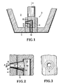
Figur 1- eine Verschlußeinrichtung an einem Schmelzengefäß,
Figur 2- eine gegenüber
Figur 1 vergrößerte Teildarstellung, Figur 3- eine Ansicht in Richtung des Pfeiles III nach
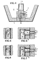
Figur 2, Figur 4- ein weiteres Ausführungsbeispiel der Verschlußeinrichtung,
Figur 5- eine gegenüber
Figur 4 vergrößerte Teilansicht, Figur 6- eine Ansicht in Richtung des Pfeiles VI nach
Figur 5, - Figur 7
- eine Alternative zu
Figur 5 und - Figur 8
- eine Ansicht in Richtung des Pfeiles VIII nach Figur 7.
- Figure 1
- a closure device on a melt vessel,
- Figure 2
- 2 shows a partial illustration enlarged compared to FIG. 1,
- Figure 3
- 2 shows a view in the direction of arrow III according to FIG. 2,
- Figure 4
- another embodiment of the closure device,
- Figure 5
- 4 shows a partial view enlarged compared to FIG. 4,
- Figure 6
- 5 shows a view in the direction of arrow VI according to FIG. 5,
- Figure 7
- an alternative to Figure 5 and
- Figure 8
- a view in the direction of arrow VIII of Figure 7.
Am Boden (1) eines Schmelzengefäßes (2) ist eine Verschlußeinrichtung (3) in der Schmelze angeordnet. Die Verschlußeinrichtung (3) besteht aus einem feuerfesten keramischen Außenrohr (4) und einem feuerfesten keramischen Innenrohr (5). Das Außenrohr (4) ist am Boden (1) abgedichtet befestigt. Das Innenrohr (5) ist um die gemeinsame Längsachse (L) der Rohre (4,5) drehbar im Außenrohr (4) gelagert. Das Außenrohr (4) weist eine seitliche Durchbrechung auf, die einen ersten Abschnitt (6) eines Durchflußkanals (7) bildet. Der erste Abschnitt (6) erstreckt sich zwischen einer Einfließöffnung (8) und einer Schließöffnung (9) des Außenrohrs (4). Die Einfließöffnung (8) liegt in der Schmelze, liegt also der Schmelze am nächsten.A closure device (3) is arranged in the melt at the bottom (1) of a melt vessel (2). The closure device (3) consists of a refractory ceramic outer tube (4) and a refractory ceramic inner tube (5). The outer tube (4) is fastened in a sealed manner to the base (1). The inner tube (5) is rotatably mounted in the outer tube (4) about the common longitudinal axis (L) of the tubes (4, 5). The outer tube (4) has a lateral opening which forms a first section (6) of a flow channel (7). The first section (6) extends between an inflow opening (8) and a closing opening (9) of the outer tube (4). The inflow opening (8) is in the melt, so it is closest to the melt.
Das Innenrohr (5) weist eine seitliche Durchbrechung auf, die einen zweiten Abschnitt (10) des Durchflußkanals (7) bildet. Der zweite Abschnitt (10) erstreckt sich zwischen einer Schließöffnung (11) des Innenrohrs (5) zu einer Ausfließöffnung (12). An die Ausfließöffnung (12) schließt sich ein von den Innenumfängen der Rohre (4,5) gebildeter Auslaufschacht (13) an.The inner tube (5) has a lateral opening which forms a second section (10) of the flow channel (7). The second section (10) extends between a closing opening (11) of the inner tube (5) to an outflow opening (12). An outlet shaft (13) formed by the inner circumferences of the pipes (4, 5) connects to the outflow opening (12).
Der Strömungsquerschnitt des Durchflußkanals (7) erweitert sich von der Einfließöffnung (8) zur Ausfließöffnung (12) in Fließrichtung (F) der Schmelze.The flow cross section of the flow channel (7) widens from the inflow opening (8) to the outflow opening (12) in the flow direction (F) of the melt.
Beim Füllen des Schmelzengefäßes (2) mit Schmelze ist das Innenrohr (5) so gegenüber dem Außenrohr (4) gedreht, daß sich die Schließöffnungen (9,11) nicht decken. Ein Schmelzenausfluß ist dadurch zunächst verhindert. Beim Einfüllen der Schmelze kann diese an der Einfließöfnung (8) oder im ersten Abschnitt (6) des Durchflußkanals (7) zu einer Metallhaut oder einem Metallpfropfen einfrieren.When filling the melt vessel (2) with melt, the inner tube (5) is turned relative to the outer tube (4) in such a way that the closing openings (9, 11) do not overlap. This initially prevents melt outflow. When filling the melt, it can freeze into a metal skin or a metal plug at the inflow opening (8) or in the first section (6) of the flow channel (7).
Beim Anstich wird das Innenrohr (5) so gedreht, daß sich die Schließöffnungen (9,11) decken. Unter dem Druck der Schmelze wird dann die Metallhaut bzw. der Metallpfropfen durch den zweiten Abschnitt (10) des Durchflußkanals (7) in den Auslaufschacht (13) befördert. Wegen der Erweiterung des Durchflußkanals (7) in Fließrichtung (F) kann die Metallhaut bzw. der Metallpfropfen nicht im Durchflußkanals (7) blockieren. Der Auslaufschacht (13) weist einen Strömungsquerschnitt auf, der wenigstens ebenso groß ist wie der Querschnitt der Ausfließöffnung (12). Im Regelfall ist der Querschnitt des Auslaufschachts (13) größer als der der Ausfließöffnung (12). Die Schmelze transportiert somit die eingefrorene Metallhaut bzw. den Metallpfropfen ohne weiteres in ein unter dem Schmelzengefäß (2) angeordnetes weiteres Gefäß.When tapping, the inner tube (5) is turned so that the closing openings (9, 11) overlap. Under the pressure of the melt, the metal skin or the metal plug is then conveyed through the second section (10) of the flow channel (7) into the outlet shaft (13). Because of the expansion of the flow channel (7) in the flow direction (F), the metal skin or the metal plug cannot block in the flow channel (7). The outlet shaft (13) has a flow cross section which is at least as large as the cross section of the outlet opening (12). As a rule, the cross section of the outlet shaft (13) is larger than that of the Outflow opening (12). The melt thus transports the frozen metal skin or the metal plug without further ado into a further vessel arranged under the melt vessel (2).
Beim Ausführungsbeispiel nach den Figuren 1 bis 3 erweitern sich der erste Abschnitt (6) und der zweite Abschnitt (10) konisch, wobei der zweite Abschnitt (10) die konische Erweiterung des ersten Abschnitts (6) im gleichen Winkel fortsetzt (vgl. Figur 2). Die Schließöffnung (9) des Außenrohrs (4) ist geringfügig größer als die Schließöffnung (11) des Innenrohrs (5).In the exemplary embodiment according to FIGS. 1 to 3, the first section (6) and the second section (10) widen conically, the second section (10) continuing the conical widening of the first section (6) at the same angle (cf. FIG. 2 ). The closing opening (9) of the outer tube (4) is slightly larger than the closing opening (11) of the inner tube (5).
Bei den Ausführungsbeispielen nach den Figuren 4 bis 8 ist der Durchflußkanal (7) stufenartig erweitert. Dabei ist dessen erster Abschnitt (6) kreiszylindrisch. Sein Strömungsquerschnitt ist kleiner als der des im Innenrohr (5) verlaufenden zweiten Abschnitts (10).In the exemplary embodiments according to FIGS. 4 to 8, the flow channel (7) is widened in steps. Its first section (6) is circular cylindrical. Its flow cross section is smaller than that of the second section (10) running in the inner tube (5).
Beim Ausführungsbeispiel nach den Figuren 5 und 6 ist der zweite Abschnitt (10) ovalzylindrisch geformt. Die längere Achse des Ovals liegt parallel zur Längsachse (L). Die Mittelpunkte des kreiszylindrischen ersten Abschnitts (6) und des ovalzylindrischen zweiten Abschnitts (10) sind gegeneinander versetzt (vgl. Figur 6).In the exemplary embodiment according to FIGS. 5 and 6, the second section (10) is oval-cylindrical in shape. The longer axis of the oval is parallel to the longitudinal axis (L). The center points of the circular-cylindrical first section (6) and the oval-cylindrical second section (10) are offset from one another (cf. FIG. 6).
Beim Ausführungsbeispiel nach Figur 7 und 8 ist auch der zweite Abschnitt (10) kreiszylindrisch ausgebildet, wobei sich die Mittelpunkte des ersten Abschnitts (6) und des zweiten Abschnitts (10) decken.In the embodiment according to FIGS. 7 and 8, the second section (10) is also circular cylindrical, wherein the centers of the first section (6) and the second section (10) coincide.
Dadurch, daß die Wandung des zweiten Abschnitts (10) gegenüber der Wandung des ersten Abschnitts (6) zurückspringt, kann eine im ersten Abschnitt (6) eingefrorene Metallhaut oder Metallpfropfen ohne weiteres durch den zweiten Abschnitt (10) in den Auslaufschacht (13) abgeführt werden.Due to the fact that the wall of the second section (10) springs back relative to the wall of the first section (6), a metal skin or metal plug frozen in the first section (6) can easily be discharged through the second section (10) into the outlet shaft (13) will.
Im Rahmen der Erfindung liegen auch Ausführungsbeispiele, bei denen die beschriebenen Teilmerkmale der verschiedenen Ausführungsbeispiele kombiniert sind. Beispielsweise ist es möglich, den ersten Abschnitt (6) konisch wie in Figur 2 und den zweiten Abschnitt (10) zylindrisch wie in den Figuren 5,6 oder den Figuren 7,8 auszubilden, wobei dann die Schließöffnung (9) des Außenrohrs (4) beträchtlich kleiner ist als die Schließöffnung (11) des Innenrohrs (5).Exemplary embodiments are also within the scope of the invention, in which the described partial features of the various exemplary embodiments are combined. For example, it is possible to design the first section (6) conically as in FIG. 2 and the second section (10) cylindrically as in FIGS. 5, 6 or 7, 8, with the closing opening (9) of the outer tube (4 ) is considerably smaller than the closing opening (11) of the inner tube (5).
Claims (7)
dadurch gekennzeichnet,
daß sich der Strömungsquerschnitt des Durchflußkanals (7) von der Einfließöffnung (8) zu der Ausfließöffnung (12) erweitert.Closure device for a metallurgical melt vessel with a refractory outer tube and a refractory inner tube mounted therein, the outer tube and the inner tube each having at least one closing opening, one tube being movable relative to the other tube from a closed position into a passage position of the closing openings and the closing openings lie in a flow channel which extends from an inflow opening located in the melt to an outflow opening located in the flow direction behind the closing opening of the inner tube,
characterized,
that the flow cross section of the flow channel (7) widens from the inflow opening (8) to the outflow opening (12).
dadurch gekennzeichnet,
daß der Strömungsquerschnitt des Durchflußkanals (7) in seinem ersten Abschnitt (6), der zwischen der Einfließöffnung (8) und der Schließöffnung (9) des Außenrohrs (4) liegt, enger ist als der Strömungsquerschnitt des Durchflußkanals (7) in seinem zweiten Abschnitt (10), der zwischen der Schließöffnung (11) des Innenrohrs (5) und der Ausfließöffnung (12) liegt.Closure device according to claim 1,
characterized,
that the flow cross section of the flow channel (7) in its first section (6), which lies between the inflow opening (8) and the closing opening (9) of the outer tube (4), is narrower than the flow cross section of the flow channel (7) in its second section (10) which lies between the closing opening (11) of the inner tube (5) and the outflow opening (12).
dadurch gekennzeichnet,
daß der erste Abschnitt (6) vom Außenrohr (4) und der zweite Abschnitt (10) vom Innenrohr (5) gebildet ist.Closure device according to claim 2,
characterized,
that the first section (6) of the outer tube (4) and the second section (10) of the inner tube (5) is formed.
dadurch gekennzeichnet,
daß sich der erste Abschnitt (6) und/oder der zweite Abschnitt (10) konisch erweitert.Closure device according to claim 2 or 3,
characterized,
that the first section (6) and / or the second section (10) widens conically.
dadurch gekennzeichnet,
daß sich der Durchflußkanal (7) stufenartig erweitert.Closure device according to one of the preceding claims 1 to 3,
characterized,
that the flow channel (7) widens in steps.
dadurch gekennzeichnet,
daß die stufenartige Erweiterung dadurch gebildet ist, daß die Schließöffnung (11) des Innenrohrs (5) größer als die des Außenrohrs (4) ist.Closure device according to claim 5,
characterized,
that the step-like expansion is formed by that the closing opening (11) of the inner tube (5) is larger than that of the outer tube (4).
dadurch gekennzeichnet,
daß der Querschnitt des zweiten Abschnitts (10) oval ist.Closure device according to one of the preceding claims,
characterized,
that the cross section of the second section (10) is oval.
Applications Claiming Priority (2)
| Application Number | Priority Date | Filing Date | Title |
|---|---|---|---|
| DE4001095A DE4001095A1 (en) | 1990-01-17 | 1990-01-17 | LOCKING DEVICE FOR A MELTING VESSEL |
| DE4001095 | 1990-01-17 |
Publications (2)
| Publication Number | Publication Date |
|---|---|
| EP0437726A2 true EP0437726A2 (en) | 1991-07-24 |
| EP0437726A3 EP0437726A3 (en) | 1992-04-22 |
Family
ID=6398178
Family Applications (1)
| Application Number | Title | Priority Date | Filing Date |
|---|---|---|---|
| EP19900123654 Withdrawn EP0437726A3 (en) | 1990-01-17 | 1990-12-08 | Closure device for a molten metal vessel |
Country Status (9)
| Country | Link |
|---|---|
| US (1) | US5145634A (en) |
| EP (1) | EP0437726A3 (en) |
| JP (1) | JPH0569113A (en) |
| KR (1) | KR910014166A (en) |
| CN (1) | CN1053377A (en) |
| BR (1) | BR9100172A (en) |
| CA (1) | CA2034255A1 (en) |
| DE (1) | DE4001095A1 (en) |
| ZA (1) | ZA9010051B (en) |
Families Citing this family (4)
| Publication number | Priority date | Publication date | Assignee | Title |
|---|---|---|---|---|
| US5330162A (en) * | 1992-07-29 | 1994-07-19 | Meichuseiki Kabushiki Kaisha | Dipping and pouring apparatus for molten metal |
| CH688712A5 (en) * | 1994-07-22 | 1998-01-30 | Stopinc Ag | Vessel closure member on the spout of a molten metal containing. |
| US8210402B2 (en) | 2009-02-09 | 2012-07-03 | Ajf, Inc. | Slag control shape device with L-shape loading bracket |
| CN106311981B (en) * | 2016-11-17 | 2018-03-02 | 遵义市润丰源钢铁铸造有限公司 | The apparatus for pouring of lost foam casting casting |
Family Cites Families (10)
| Publication number | Priority date | Publication date | Assignee | Title |
|---|---|---|---|---|
| US2224514A (en) * | 1939-04-28 | 1940-12-10 | United American Metals Corp | Melting pot |
| CH420498A (en) * | 1965-03-09 | 1966-09-15 | Concast Ag | Device for changing the position of the casting stream, in particular during continuous casting |
| CH449861A (en) * | 1967-02-24 | 1968-01-15 | Metacon Ag | Casting device |
| US3511471A (en) * | 1968-01-19 | 1970-05-12 | Concast Inc | Ladle stopper |
| CH500794A (en) * | 1969-06-09 | 1970-12-31 | Metacon Ag | Slide gate on a pouring vessel intended to hold liquid metal |
| JPS6045025B2 (en) * | 1978-08-24 | 1985-10-07 | 日本鋼管株式会社 | Tandytsu molten metal discharge device |
| CH649149A5 (en) * | 1980-05-22 | 1985-04-30 | Stopinc Ag | TURNTABLE SLIDER FOR MELTING CASES. |
| DE3731600A1 (en) * | 1987-09-19 | 1989-04-06 | Didier Werke Ag | TURNTABLE CLOSURE FOR A METALURIGAN TUBE AND ROTOR AND / OR STATOR FOR SUCH A TURNOVER |
| GB8723059D0 (en) * | 1987-10-01 | 1987-11-04 | Foseco Int | Rotary pouring nozzle |
| DE3926678C2 (en) * | 1989-08-12 | 1994-09-01 | Didier Werke Ag | Closing and regulating device for a metallurgical vessel |
-
1990
- 1990-01-17 DE DE4001095A patent/DE4001095A1/en not_active Withdrawn
- 1990-12-08 EP EP19900123654 patent/EP0437726A3/en not_active Withdrawn
- 1990-12-13 ZA ZA9010051A patent/ZA9010051B/en unknown
- 1990-12-13 JP JP2419187A patent/JPH0569113A/en active Pending
- 1990-12-19 US US07/631,058 patent/US5145634A/en not_active Expired - Fee Related
-
1991
- 1991-01-10 KR KR1019910000297A patent/KR910014166A/en not_active Withdrawn
- 1991-01-16 CN CN91100276A patent/CN1053377A/en active Pending
- 1991-01-16 CA CA002034255A patent/CA2034255A1/en not_active Abandoned
- 1991-01-16 BR BR919100172A patent/BR9100172A/en unknown
Also Published As
| Publication number | Publication date |
|---|---|
| KR910014166A (en) | 1991-08-31 |
| CN1053377A (en) | 1991-07-31 |
| JPH0569113A (en) | 1993-03-23 |
| BR9100172A (en) | 1991-10-22 |
| US5145634A (en) | 1992-09-08 |
| CA2034255A1 (en) | 1991-07-18 |
| ZA9010051B (en) | 1991-10-30 |
| DE4001095A1 (en) | 1991-07-18 |
| EP0437726A3 (en) | 1992-04-22 |
Similar Documents
| Publication | Publication Date | Title |
|---|---|---|
| EP0630712B1 (en) | Immersion nozzle | |
| DE2706850A1 (en) | ROLLER WITH INTERNAL COOLING | |
| DE2162977A1 (en) | METHOD AND DEVICE FOR MANUFACTURING METAL RODS IN CONTINUOUS CASTING AND CONTINUOUSLY CAST METAL BAR MANUFACTURED BY THIS PROCESS | |
| EP0437726A2 (en) | Closure device for a molten metal vessel | |
| DE3911736C2 (en) | Closing and / or regulating element for a metallurgical vessel | |
| DE2532528A1 (en) | PROCEDURE FOR SETTING A PRESET DETAILED DISTRIBUTION LAW OF FLOW IN A FLOWING MEDIUM FLOW AND DEVICE FOR CARRYING OUT THE PROCESS | |
| DE3152917T1 (en) | METAL CASTING MOLD AND VENTILATION DEVICE THEREFOR | |
| DE2822582C3 (en) | Coolant guide and rolling stock guide device for the intermittent cooling of rolling stock, in particular wire, fine iron or the like. | |
| DE3939241C2 (en) | Locking and / or regulating device | |
| DE7611054U1 (en) | DEVICE FOR SEPARATING GAS COMPONENTS FROM LIQUID MEDIA | |
| EP0040257B1 (en) | Drainage pipe with triangular cross section | |
| DE19700462C2 (en) | Static mixer | |
| EP0561181A2 (en) | Tap pipe for a converter or an electric arc furnace | |
| DE9207096U1 (en) | Screw press | |
| EP0436813A2 (en) | Shut-off and/or control device | |
| DE3419769C2 (en) | ||
| DE19859032C2 (en) | Casting filter for casting metal alloy | |
| EP0263779A2 (en) | Installation for continuous casting of molten metal | |
| AT401027B (en) | CONTINUOUS CASTING MACHINE FOR CONTINUOUS HORIZONTAL CONTINUOUS CASTING OF METALS | |
| DE2715450C3 (en) | A pouring device with a refill preventing device for insertion into the neck of a bottle | |
| DE2429684A1 (en) | USE FOR USE IN A HEAD OF A LIVING BEING | |
| DE2306321C3 (en) | Device for increasing the volume flow through drainage pipes | |
| DE1213090B (en) | Method and device for the continuous casting of metal bars | |
| DE625616C (en) | Spinneret for making seamless hoses | |
| DE2109065C (en) | Rotary kiln with a closed pre-cooler at its outlet |
Legal Events
| Date | Code | Title | Description |
|---|---|---|---|
| PUAI | Public reference made under article 153(3) epc to a published international application that has entered the european phase |
Free format text: ORIGINAL CODE: 0009012 |
|
| 17P | Request for examination filed |
Effective date: 19910107 |
|
| AK | Designated contracting states |
Kind code of ref document: A2 Designated state(s): AT BE CH DE DK ES FR GB GR IT LI LU NL SE |
|
| PUAL | Search report despatched |
Free format text: ORIGINAL CODE: 0009013 |
|
| AK | Designated contracting states |
Kind code of ref document: A3 Designated state(s): AT BE CH DE DK ES FR GB GR IT LI LU NL SE |
|
| STAA | Information on the status of an ep patent application or granted ep patent |
Free format text: STATUS: THE APPLICATION HAS BEEN WITHDRAWN |
|
| 17Q | First examination report despatched |
Effective date: 19930609 |
|
| 18W | Application withdrawn |
Withdrawal date: 19930622 |