EP0437672B1 - Method of manufacturing intermediate concrete products, formwork for manufacturing said products, and apparatus for carrying out said method - Google Patents
Method of manufacturing intermediate concrete products, formwork for manufacturing said products, and apparatus for carrying out said method Download PDFInfo
- Publication number
- EP0437672B1 EP0437672B1 EP90114902A EP90114902A EP0437672B1 EP 0437672 B1 EP0437672 B1 EP 0437672B1 EP 90114902 A EP90114902 A EP 90114902A EP 90114902 A EP90114902 A EP 90114902A EP 0437672 B1 EP0437672 B1 EP 0437672B1
- Authority
- EP
- European Patent Office
- Prior art keywords
- concrete
- formwork
- nozzles
- cast
- bar
- Prior art date
- Legal status (The legal status is an assumption and is not a legal conclusion. Google has not performed a legal analysis and makes no representation as to the accuracy of the status listed.)
- Expired - Lifetime
Links
Images


Classifications
-
- B—PERFORMING OPERATIONS; TRANSPORTING
- B28—WORKING CEMENT, CLAY, OR STONE
- B28B—SHAPING CLAY OR OTHER CERAMIC COMPOSITIONS; SHAPING SLAG; SHAPING MIXTURES CONTAINING CEMENTITIOUS MATERIAL, e.g. PLASTER
- B28B7/00—Moulds; Cores; Mandrels
- B28B7/24—Unitary mould structures with a plurality of moulding spaces, e.g. moulds divided into multiple moulding spaces by integratable partitions, mould part structures providing a number of moulding spaces in mutual co-operation
- B28B7/241—Detachable assemblies of mould parts providing only in mutual co-operation a number of complete moulding spaces
- B28B7/243—Detachable assemblies of mould parts providing only in mutual co-operation a number of complete moulding spaces for making plates, panels or similar sheet- or disc-shaped objects
-
- B—PERFORMING OPERATIONS; TRANSPORTING
- B28—WORKING CEMENT, CLAY, OR STONE
- B28B—SHAPING CLAY OR OTHER CERAMIC COMPOSITIONS; SHAPING SLAG; SHAPING MIXTURES CONTAINING CEMENTITIOUS MATERIAL, e.g. PLASTER
- B28B13/00—Feeding the unshaped material to moulds or apparatus for producing shaped articles; Discharging shaped articles from such moulds or apparatus
- B28B13/02—Feeding the unshaped material to moulds or apparatus for producing shaped articles
- B28B13/021—Feeding the unshaped material to moulds or apparatus for producing shaped articles by fluid pressure acting directly on the material, e.g. using vacuum, air pressure
Definitions
- the invention refers to a method of manufacturing intermediate concrete products according to the precharacterizing part of claim 1.
- the concrete tiles are manufactured according to a known method in such a manner that concrete of dry to damp consistency, having as a rule no additional dyes, is fed onto a horizontal formwork and consolidated into the corresponding form by means of vibrating and compressing. Further, raw tile formed in such a manner proceeds into a heating chamber in which there prevail specified climatic conditions (humidity of 95% and temperature of up to 65 °C) and reposes until it has won approximately 50% of its ultimate strength. Only then the tile can be lifted out of the horizontal formwork and proceeded to further treatment, e.g. sorting, colouring, storage.
- climatic conditions humidity of 95% and temperature of up to 65 °C
- a disadvantage of the concrete of said consistency is also a relatively high sensitivity to changes of volume in loose and consolidated state, which results in a change of quality of the product even at the slightest changes of input material, e.g. humidity.
- a further disadvantage of the known method lies in a high sound pressure level occurring at consolidating the concrete by means of vibrations, due to intensive vibrating of the concrete there also appear powerful vibrations in the surrounding of the tile producing machine.
- deformations of the horizontal metal formworks take place, which results in the necessity of frequently replacing the formworks to avoid deformed products.
- Another disadvantage of the known method lies in the circumstance that the side of the concrete product-tile facing away from the formwork is free, i.e. unprotected, wherefore damages can occur on the tile. During the time in which the tile lies in the chamber, even the entire surface of the tile which at use is exposed to weather can be damaged due to possible change of humidity or temperature.
- a further disadvantage lies in that a great amount of space is needed for the aforementioned method of manufacturing tiles as the daily production of e.g. 100.000 tiles requires approximately 12.000 m3 of room which, in addition, should be heated to a temperature of approximately 65 °C , which results in a relatively high power consumption.
- the GB-A-1 579 544 generally a box connected to a plurality of tubes is known for feeding concrete into a plurality of casts; and the DD-A-259 576 shows generally a distributor system for liquids, especially chemical agents and pharmaceutical agents.
- the object of the invention is to provide a method of manufacturing concrete products, preferably tiles, according to the precharacterizing part of claim 1, in which the aforementioned disadvantages will be avoided.
- the feature of the present method according to the invention lies in the use of concrete of a cast consistency, which ensures uniformity of the composition and unsegregability of concrete, the possibility of forwarding under pressure to the charging head and filling up a row of formworks during one production cycle with exact material dosing.
- Cast concrete possesses the features of good and quick homogeneity even in the case when very small quantities of chemical or mineral additives are added.
- durability of the material e.g. resistance to freezing and chemical influence resistance and high quality of pigmentizing of concrete mass.
- Components of the cast concrete ensuring the necessary features of fresh concrete admixture are as follows:
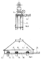
- Fig. 1 showing a schematic diagram of an apparatus for carrying out said method.
- Concrete of the aforementioned composition and consistency is prepared in a common counterflow concrete plant. Concrete prepared in such a manner is delivered into a storage bin 1 of a screw pump 2, by means of which it is conveyed through a pipe line 3 to a charging head 4 of an apparatus according to the invention.
- the charging head 4 is arranged for filling up a row of formworks 5 whereby concrete is contractionally discharged into each formwork 5 by means of discharging nozzles 6.
- Pressure required for operation of the system is maintained by means of automatic synchronised working of the pump 2 and of the unit for opening and closing the stops and unit for lowering and lifting the head 4, whereby it is particularly important that in all nozzles 6 for filling up the formworks 5 the same pressure is ensured.
- Its value at the outlet of each nozzle 6 equals from 0,1 bar to 0,5 bar, preferably 0,2 bar. Due to technological features of concrete, said formworks must be water-impermeable and made of thermally insulating material, e.g. polyurethane resin.
- Each nozzle 6 of the charging head 4 is thrust to the area of the bottom of each formwork 5 and then concrete is conveyed therein.
- the charging head 4 and the nozzles 6 are lifted up with constant velocity till the formworks 5 are completely filled up.
- the nozzles 6 may not be lifted over the level of the concrete being cast in any case.
- the lifting velocity of the charging head 4 and thereby of the nozzles 6 is adjusted to the largest cross-section of the product being cast, and in the particular case equals from 0,05 ms ⁇ 1 to 0,2 ms ⁇ 1, preferably 0,1 ms ⁇ 1.
- the formworks 5 When the formworks 5 are filled up they are transferred to a setting place.
- said formworks are made of thermally insulating material an intrinsic energy-hydration heat of the cement is exploited released during setting time for the concrete.
- the concrete is aging practically in adiabatic conditions, and after approximately 24 hours reaches a temperature of approximately 55 °C above ambient temperature, which in the particular case equals 20 °C without additional heating wherefore any further thermal treatment is superfluous.
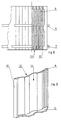
- Figs. 8, 9, 10 show, just for further elucidation of the method according to the invention, a formwork 5 for casting concrete tiles.
- Said formwork comprises a pair of frames 7, 8 clamping together a plurality of elements 9 made of waterimpermeable and thermally insulating material, e.g. polyurethane resin, the form of which corresponds to a product desired, and in the particular case corresponding to a tile.
- Each element 9 is along both vertical sides provided with a pair of thickenings 10, 11 whereby facing sides of each thickening 10, 11 of two adjacent elements 9 are parallel abutting slitlessly to each other.
- the element 9 is at its first, in the particular case its lower, end provided with a web 12 being essentially perpendicular to said element and running between the thickenings 10, 11.
- a web 12 being essentially perpendicular to said element and running between the thickenings 10, 11.
- the elements 9 are formed in such a manner that their first flat side 14 corresponds to the first side of the tile, their second flat side 15 corresponding to the second side thereof.
- the elements 9 are arranged vertically, i.e. concrete is cast from the upper side. Two elements 9 are needed to produce one tile and n+1 of said elements are needed to produce n tiles.
- the apparatus comprises a storage bin 1 arranged on a screw pump 2. The latter is driven through a gearbox 2' by means of a drive 2''.
- a pipe line 3 fixed on a stand 3' is connected to the discharge end of the pump 2.
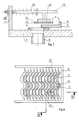
- the other end of the pipe line 3 is connected to an essentially trapezoidal charging head 4 to which a row of discharging nozzles 6 is interconnected.
- Said nozzles are removably fixed to a bottom 7 of the head 4 which is in the area of penetration of each nozzle 6 therethrough provided with a wear resisting plate 8.
- a blocking unit 8' is slidingly and movably arranged on the plates 8 of each row of the nozzles 6.
- Said unit comprises closures 9 being mutually rigidly connected by means of a linkage 10 which is interconnected with the pneumatic or hydraulic working cylinder 11. The latter enables simultaneous moving of all closures 9 over the plates 8 and closing and opening the nozzles 6 respectively.
- each closure 9 there are throttle knives 12 arranged slidingly and movably in the same plane as said closure and extending over the entire length of each row of nozzles 6.
- the throttle knives 12 are regarding the closure 9 staggered in their plane in the direction away from the working cylinder 11, the closures 9 being provided with a lug 9' cooperating with the knives 12.
- the side of the knives 12 facing away from the working cylinder 11 is shaped as a half-wave of a sinusoidal curve 13 the curvature of which is conditioned by mutual distance of the two utmost nozzles 6, by material cast and by the pressure for pressing material into the nozzles 6.
- the throttle knives 12 are reinforced by means of a brace fillet 14 and mutually connected by means of a linkage 15.
- a back stop 16 meshing with the linkage 15. The latter penetrates the wall 4' of the head 4 on the side facing away from the working cylinder 11 whereby the linkage 15 is between the said wall and a limit stop 17 provided with a tension-compression spring 18 which enables moving of the throttle knives 12.
- a nut 18' is screwed thereon, the stroke of the throttle knives 12 being regulated therewith.
Abstract
Description
- The invention refers to a method of manufacturing intermediate concrete products according to the precharacterizing part of claim 1.
- In building constructions as roofing tiles made of clay or concrete are used at most. Since in primary sense the production of clay tiles is locally bound to a basic stock of raw material and preferably to greater stationary plants characteristic of a high power consumption on the production spot, there asset themselves more and more concrete tiles which correspond to clay tiles both in form and quality.
- The concrete tiles are manufactured according to a known method in such a manner that concrete of dry to damp consistency, having as a rule no additional dyes, is fed onto a horizontal formwork and consolidated into the corresponding form by means of vibrating and compressing. Further, raw tile formed in such a manner proceeds into a heating chamber in which there prevail specified climatic conditions (humidity of 95% and temperature of up to 65 °C) and reposes until it has won approximately 50% of its ultimate strength. Only then the tile can be lifted out of the horizontal formwork and proceeded to further treatment, e.g. sorting, colouring, storage.
- Due to technological features of the concrete of dry to damp consistency, there exists at known methods a problem of how to attain good homogeneity and mixing of components of the concrete, particularly those which appear in small quantities (from O,5% to 5% by weight of cement) in a concrete mixture. This problem is particularly obvious in chemical admixtures for improving the persistency of the concrete product and in adding dyes into the concrete mixture. Said problems result in a variable quality of the products both in technological and in visual sense. A disadvantage of the concrete of said consistency is also a relatively high sensitivity to changes of volume in loose and consolidated state, which results in a change of quality of the product even at the slightest changes of input material, e.g. humidity.
- A further disadvantage of the known method lies in a high sound pressure level occurring at consolidating the concrete by means of vibrations, due to intensive vibrating of the concrete there also appear powerful vibrations in the surrounding of the tile producing machine. During consolidating the tiles, deformations of the horizontal metal formworks take place, which results in the necessity of frequently replacing the formworks to avoid deformed products.
- Another disadvantage of the known method lies in the circumstance that the side of the concrete product-tile facing away from the formwork is free, i.e. unprotected, wherefore damages can occur on the tile. During the time in which the tile lies in the chamber, even the entire surface of the tile which at use is exposed to weather can be damaged due to possible change of humidity or temperature.
- A further disadvantage lies in that a great amount of space is needed for the aforementioned method of manufacturing tiles as the daily production of e.g. 100.000 tiles requires approximately 12.000 m³ of room which, in addition, should be heated to a temperature of approximately 65 °C , which results in a relatively high power consumption.
- From "Der Grundbau", Armin SCHOKLITSCH, Verlag Julius Springer, Wien, 1932, page 118, line 27 - page 119,
line 3; fig. 136b; and from "Die Gründung von Bauwerken", Wolf PLAGEMANN, Wolfgang LANGNER, Verlag B.G.Teubner, Leipzig, 1973, page 106, especially page 106, lines 18-19, fig. 10.10b, it is generally known to build foundation wherein the concrete is fed into a form by a nozzle and the outlet of the nozzle is moved in that way during feeding of the concrete into the form, that the outlet of the nozzle is kept under the surface of the concrete for a certain distance. - Moreover, from the GB-A-1 579 544 generally a box connected to a plurality of tubes is known for feeding concrete into a plurality of casts; and the DD-A-259 576 shows generally a distributor system for liquids, especially chemical agents and pharmaceutical agents.
- The object of the invention is to provide a method of manufacturing concrete products, preferably tiles, according to the precharacterizing part of claim 1, in which the aforementioned disadvantages will be avoided.
- This object is according to the invention gained by means of features given in the characterizing clause of claim 1. Advantageous embodiments of the invention are defined by the
subclaims - It is understood that the present invention can be used for different intermediate concrete products too, although it is specifically described for concrete tiles.
- The invention is further described in the following preferred embodiment, reference being made to the accompanying drawings. Therein show:
- Fig. 1 a schematic diagram of an apparatus for carrying out the method according to the invention,
- Fig. 2 a side elevation of a charging head of an apparatus for carrying out the method according to the invention,
- Fig. 3 a view of the charging head in the direction of an arrow III of Fig. 2,
- Fig. 4 a vertical sectional view of the charging head,
- Fig. 5 a view in the direction of an arrow V of Fig. 4,
- Fig. 6 a detail of a blocking unit in closed position,
- Fig. 7 a detail of a blocking unit in open position,
- Fig. 8 a plan view of a formwork for manufacturing tiles according to the invention,
- Fig. 9 a sectional view of a formwork taken along the line IX-IX of Fig. 8, and
- Fig. 10 an element of a formwork according to the invention.
- The feature of the present method according to the invention lies in the use of concrete of a cast consistency, which ensures uniformity of the composition and unsegregability of concrete, the possibility of forwarding under pressure to the charging head and filling up a row of formworks during one production cycle with exact material dosing. Cast concrete possesses the features of good and quick homogeneity even in the case when very small quantities of chemical or mineral additives are added. Thus, obtaining high degree of uniform quality, there are ensured the durability of the material, e.g. resistance to freezing and chemical influence resistance and high quality of pigmentizing of concrete mass. Components of the cast concrete ensuring the necessary features of fresh concrete admixture are as follows:
- cement, preferably highly active cement,
- stone aggregate with size gradation of at most 3,2 mm and sifting of 15% to 20% through a 0,25 mm sieve,
- usual chemical admixture for lowering the surface tension of the water,
- usual chemical admixture for introducing microporosity into the cement paste,
- mineral fine-grained admixture for preventing micro-mixing (micro-segregation) of concrete and decreasing permeability of the concrete admixture to water,
- mineral fine-aggregate admixture for volume reduction of concrete mass,
- water, and
- mineral dyes.
- The method according to the invention will be further described in detail referring to Fig. 1 showing a schematic diagram of an apparatus for carrying out said method. Concrete of the aforementioned composition and consistency is prepared in a common counterflow concrete plant. Concrete prepared in such a manner is delivered into a storage bin 1 of a
screw pump 2, by means of which it is conveyed through apipe line 3 to a charginghead 4 of an apparatus according to the invention. In the given case thecharging head 4 is arranged for filling up a row offormworks 5 whereby concrete is contractionally discharged into eachformwork 5 by means of dischargingnozzles 6. Pressure required for operation of the system is maintained by means of automatic synchronised working of thepump 2 and of the unit for opening and closing the stops and unit for lowering and lifting thehead 4, whereby it is particularly important that in allnozzles 6 for filling up theformworks 5 the same pressure is ensured. Its value at the outlet of eachnozzle 6 equals from 0,1 bar to 0,5 bar, preferably 0,2 bar. Due to technological features of concrete, said formworks must be water-impermeable and made of thermally insulating material, e.g. polyurethane resin. Eachnozzle 6 of thecharging head 4 is thrust to the area of the bottom of eachformwork 5 and then concrete is conveyed therein. - When the
formwork 5 is filled up for essentially one third by the height, thecharging head 4 and thenozzles 6 are lifted up with constant velocity till theformworks 5 are completely filled up. Thenozzles 6 may not be lifted over the level of the concrete being cast in any case. The lifting velocity of thecharging head 4 and thereby of thenozzles 6 is adjusted to the largest cross-section of the product being cast, and in the particular case equals from 0,05 ms⁻¹ to 0,2 ms⁻¹, preferably 0,1 ms⁻¹. - When the
formworks 5 are filled up they are transferred to a setting place. As said formworks are made of thermally insulating material an intrinsic energy-hydration heat of the cement is exploited released during setting time for the concrete. In such a manner the concrete is aging practically in adiabatic conditions, and after approximately 24 hours reaches a temperature of approximately 55 °C above ambient temperature, which in the particular case equals 20 °C without additional heating wherefore any further thermal treatment is superfluous. - Figs. 8, 9, 10 show, just for further elucidation of the method according to the invention, a
formwork 5 for casting concrete tiles. Said formwork comprises a pair offrames elements 9 made of waterimpermeable and thermally insulating material, e.g. polyurethane resin, the form of which corresponds to a product desired, and in the particular case corresponding to a tile. Eachelement 9 is along both vertical sides provided with a pair ofthickenings adjacent elements 9 are parallel abutting slitlessly to each other. Theelement 9 is at its first, in the particular case its lower, end provided with aweb 12 being essentially perpendicular to said element and running between thethickenings elements 9 said web slitlessly rests against theadjacent element 9 forming a bottom 13 of theformwork 5 in the essence. Theelements 9 are formed in such a manner that their firstflat side 14 corresponds to the first side of the tile, their secondflat side 15 corresponding to the second side thereof. In theformwork 5 theelements 9 are arranged vertically, i.e. concrete is cast from the upper side. Twoelements 9 are needed to produce one tile and n+1 of said elements are needed to produce n tiles. - Just for further elucidation of the method according to the invention, referring to Figs. 1 to 7, an apparatus for carrying out the method of manufacturing concrete products, preferably tiles,is described. The apparatus comprises a storage bin 1 arranged on a
screw pump 2. The latter is driven through a gearbox 2' by means of a drive 2''. Apipe line 3 fixed on a stand 3' is connected to the discharge end of thepump 2. The other end of thepipe line 3 is connected to an essentiallytrapezoidal charging head 4 to which a row of dischargingnozzles 6 is interconnected. Said nozzles are removably fixed to abottom 7 of thehead 4 which is in the area of penetration of eachnozzle 6 therethrough provided with awear resisting plate 8. Sides of theplate 8 facing away from the bottom 7 lie in the plane parallel thereto. A blocking unit 8' is slidingly and movably arranged on theplates 8 of each row of thenozzles 6. Said unit comprisesclosures 9 being mutually rigidly connected by means of alinkage 10 which is interconnected with the pneumatic or hydraulic workingcylinder 11. The latter enables simultaneous moving of allclosures 9 over theplates 8 and closing and opening thenozzles 6 respectively. - In the area above each
closure 9 there arethrottle knives 12 arranged slidingly and movably in the same plane as said closure and extending over the entire length of each row ofnozzles 6. Thethrottle knives 12 are regarding theclosure 9 staggered in their plane in the direction away from the workingcylinder 11, theclosures 9 being provided with a lug 9' cooperating with theknives 12. The side of theknives 12 facing away from the workingcylinder 11 is shaped as a half-wave of asinusoidal curve 13 the curvature of which is conditioned by mutual distance of the twoutmost nozzles 6, by material cast and by the pressure for pressing material into thenozzles 6. On their side facing away from the bottom 7 thethrottle knives 12 are reinforced by means of abrace fillet 14 and mutually connected by means of alinkage 15. On thelinkage 10 there is provided aback stop 16 meshing with thelinkage 15. The latter penetrates the wall 4' of thehead 4 on the side facing away from the workingcylinder 11 whereby thelinkage 15 is between the said wall and alimit stop 17 provided with a tension-compression spring 18 which enables moving of thethrottle knives 12. To a part of thelinkage 15 projecting through the wall 4' a nut 18' is screwed thereon, the stroke of thethrottle knives 12 being regulated therewith. - The operation of the blocking unit is further described with reference to Figs. 6 and 7. In the starting position the
nozzles 6 are closed by means ofclosures 9. The lugs 9' arranged on said closures hold thethrottle knives 12 in a closed position. Moving theclosures 9 by means of thelinkage 10 and the workingcylinder 11 in the direction towards thecylinder 11 reflects in an opening of thenozzles 6. Thespring 18, which is compressed in the starting position, repulses thethrottle knives 12 by means of thelimit stop 17 and thelinkage 15 in the same direction as theclosures 9 are moving. Thespring 18 acts onto thethrottle knives 12 until the nut 18' rests against the wall 4' of thehead 4. Thus, theclosures 9 continue to move so that they completely open the entrance into thenozzles 6. Between that side of eachthrottle knife 12 lying in front of thecurve 13, and the lug 9' of eachclosure 9 there is a distance a atnozzles 6 completely open, in dependence upon the material cast. Thus, entries into thenozzles 6 due tocurve 13 on theknives 12 overlap in a different degree when theclosures 9 are in the open position. The more the entrance of eachnozzle 6 lies away from the place of supply of the concrete mass into the charginghead 4, the smaller the degree of overlapping. In such a manner the same pressure is ensured at the entrance into eachnozzle 6 and, therefore, at the outlet thereof for, the smaller the degree of overlapping, the lower the pressure drop. The degree of overlapping thus represents the function of the mutual distance of the utmost twonozzles 6, of the material cast, and of the pressure for pressing material into thenozzles 6. - The entrance into the
nozzles 6 is closed by means of the workingcylinder 11 pushing theclosures 9 through thelinkage 10 and the lug 9' of eachclosure 9 pushing thethrottle knives 12 into the starting position. Thespring 18 is therefore compressed and the blocking unit 8' is ready for the next working cycle.
Claims (3)
- A method of manufacturing intermediate concrete products, wherein a non-segregable concrete of cast consistency is pressed contractionally through at least one nozzle into at least one corresponding formwork, whereby the nozzle is located in the bottom area of the formwork, and when the latter being filled up for essentially one third by the height the nozzle is lifted up with a constant velocity from the formwork in such a manner that it is not lifted over the level of concrete being cast in any case, characterized in that the formwork ist made of a water-impermeable and thermally insulation material, the concrete is aging practically in adiabatic conditions, and the pressure value of dosing of concrete at the outlet of each nozzle (6) equals from 0,1 bar to 0,5 bar, preferably 0,2 bar.
- A method according to claim 1, characterized in that the lifting velocity of the nozzles equals from 0,05 ms⁻¹ to 0,2 ms⁻¹, preferably 0,1 ms⁻¹.
- A method according to claim 1, characterized in that the hydration heat of the cement is exploited released during setting time for the concrete.
Applications Claiming Priority (2)
| Application Number | Priority Date | Filing Date | Title |
|---|---|---|---|
| YU7290A YU7290A (en) | 1990-01-16 | 1990-01-16 | PROCEDURE FOR THE MANUFACTURE OF CONCRETE SEMI-FINISHED PRODUCTS, PREPARATION FOR THE MANUFACTURE OF CONCRETE SEMI-FINISHED PRODUCTS AND DEVICE FOR PERFORMING THE PROCEDURE |
| YU72/90 | 1990-01-16 |
Publications (2)
| Publication Number | Publication Date |
|---|---|
| EP0437672A1 EP0437672A1 (en) | 1991-07-24 |
| EP0437672B1 true EP0437672B1 (en) | 1994-06-08 |
Family
ID=25548209
Family Applications (1)
| Application Number | Title | Priority Date | Filing Date |
|---|---|---|---|
| EP90114902A Expired - Lifetime EP0437672B1 (en) | 1990-01-16 | 1990-08-02 | Method of manufacturing intermediate concrete products, formwork for manufacturing said products, and apparatus for carrying out said method |
Country Status (7)
| Country | Link |
|---|---|
| EP (1) | EP0437672B1 (en) |
| AT (1) | ATE106792T1 (en) |
| CA (1) | CA2025840A1 (en) |
| DE (1) | DE69009724T2 (en) |
| FI (1) | FI903951A (en) |
| SI (1) | SI9010072A (en) |
| YU (1) | YU7290A (en) |
Cited By (2)
| Publication number | Priority date | Publication date | Assignee | Title |
|---|---|---|---|---|
| US20110183023A1 (en) * | 2005-04-28 | 2011-07-28 | Monier Technical Centre Limited | Method and plant for the manufacture of building products |
| CN106703412A (en) * | 2015-07-13 | 2017-05-24 | 马义和 | Building component 3D printing sprayer internally provided with vibrating bar |
Families Citing this family (3)
| Publication number | Priority date | Publication date | Assignee | Title |
|---|---|---|---|---|
| MY120547A (en) * | 1997-08-29 | 2005-11-30 | Boral Resources Nsw Pty Ltd | Building panel and method and apparatus of forming same |
| NL1013857C2 (en) * | 1999-12-15 | 2001-06-25 | Hollandsche Betongroep Nv | Method and device for forming a concrete element. |
| CH711101A2 (en) * | 2015-05-18 | 2016-11-30 | Airlight Energy Ip Sa | Process for producing a solid concrete work piece and solid concrete workpieces. |
Family Cites Families (2)
| Publication number | Priority date | Publication date | Assignee | Title |
|---|---|---|---|---|
| FR2341714A1 (en) * | 1976-02-23 | 1977-09-16 | Centre Etd Rech Ind Beton | PREFABRICATED CONSTRUCTION BLOCK AND METHOD AND INSTALLATION FOR ITS MANUFACTURING |
| DD259576A1 (en) * | 1987-04-10 | 1988-08-31 | Saechsisches Serumwerk | DISTRIBUTION ORGANIZATION FOR THE DISTRIBUTION OF SMALL DEFINED FLUID QUANTITIES |
-
1990
- 1990-01-16 SI SI9010072A patent/SI9010072A/en unknown
- 1990-01-16 YU YU7290A patent/YU7290A/en unknown
- 1990-08-02 DE DE69009724T patent/DE69009724T2/en not_active Expired - Fee Related
- 1990-08-02 AT AT90114902T patent/ATE106792T1/en not_active IP Right Cessation
- 1990-08-02 EP EP90114902A patent/EP0437672B1/en not_active Expired - Lifetime
- 1990-08-09 FI FI903951A patent/FI903951A/en not_active Application Discontinuation
- 1990-09-20 CA CA002025840A patent/CA2025840A1/en not_active Abandoned
Cited By (3)
| Publication number | Priority date | Publication date | Assignee | Title |
|---|---|---|---|---|
| US20110183023A1 (en) * | 2005-04-28 | 2011-07-28 | Monier Technical Centre Limited | Method and plant for the manufacture of building products |
| CN106703412A (en) * | 2015-07-13 | 2017-05-24 | 马义和 | Building component 3D printing sprayer internally provided with vibrating bar |
| CN106703412B (en) * | 2015-07-13 | 2019-04-26 | 马义和 | A kind of building element 3D printing spray head including vibrating head |
Also Published As
| Publication number | Publication date |
|---|---|
| EP0437672A1 (en) | 1991-07-24 |
| DE69009724D1 (en) | 1994-07-14 |
| YU7290A (en) | 1992-09-07 |
| DE69009724T2 (en) | 1994-12-15 |
| SI9010072A (en) | 1997-10-31 |
| FI903951A (en) | 1991-07-17 |
| ATE106792T1 (en) | 1994-06-15 |
| CA2025840A1 (en) | 1991-07-17 |
| FI903951A0 (en) | 1990-08-09 |
Similar Documents
| Publication | Publication Date | Title |
|---|---|---|
| CA1164191A (en) | Process and apparatus for the production of calcium silicate-containing stone blanks useful in constructing building walls | |
| US6213754B1 (en) | Apparatus for manufacturing concrete masonry units | |
| CN107538607A (en) | A kind of production line and production method of heat preservation dismounting-free formwork for building | |
| CN102555036A (en) | Full-automatic production equipment for expanded perlite core board of fire door and production method thereof | |
| EP0437672B1 (en) | Method of manufacturing intermediate concrete products, formwork for manufacturing said products, and apparatus for carrying out said method | |
| NO160357B (en) | PROCEDURE FOR DEHYDROGENERATION OF HYDROCARBONES. | |
| US3728211A (en) | Reinforced composite | |
| US9492944B2 (en) | Agitator grid with adjustable restrictor elements for concrete block machine | |
| CN218019244U (en) | Distributing device capable of uniformly distributing slurry | |
| RU2470773C2 (en) | Perfecting machines for continuous production of parts from stressed concrete or reinforced concrete | |
| CN107538608A (en) | A kind of Combined production line and production method of heat preservation dismounting-free formwork for building | |
| US1846290A (en) | Apparatus for making roof tiles | |
| CN207027844U (en) | A kind of production line of heat preservation dismounting-free formwork for building | |
| CN108789801A (en) | Thin material and homogenizing device in heat preservation dismounting-free formwork production process and process | |
| US3250835A (en) | Method for producing concrete and reinforced concrete slabs and substantially flat structural elements | |
| CN207772064U (en) | Thin material in heat preservation dismounting-free formwork production process and homogenizing device | |
| US1594310A (en) | Method and apparatus for feeding concrete and the like | |
| CN109958276A (en) | A kind of plant-fibre type heat preservation dismounting-free formwork and production method | |
| CN207387965U (en) | A kind of homogenizing device in heat preservation dismounting-free formwork production process | |
| DE102004027920B4 (en) | Plant for filling hollow blocks with thermal insulation has the filler components supplied from dry silos and premixed before final mixing with water and injecting into the blocks on a conveyor feed | |
| CN1137320C (en) | Technology for producing light-weight multi-layer plate | |
| US2104293A (en) | Brick and tile machine | |
| CN207390533U (en) | A kind of thin material material homogenizer in heat preservation dismounting-free formwork production process | |
| CN220279966U (en) | Hollow brick production equipment | |
| CN116766401B (en) | Concrete feeding device |
Legal Events
| Date | Code | Title | Description |
|---|---|---|---|
| PUAI | Public reference made under article 153(3) epc to a published international application that has entered the european phase |
Free format text: ORIGINAL CODE: 0009012 |
|
| 17P | Request for examination filed |
Effective date: 19901231 |
|
| AK | Designated contracting states |
Kind code of ref document: A1 Designated state(s): AT DE FR GB IT |
|
| 17Q | First examination report despatched |
Effective date: 19921208 |
|
| GRAA | (expected) grant |
Free format text: ORIGINAL CODE: 0009210 |
|
| AK | Designated contracting states |
Kind code of ref document: B1 Designated state(s): AT DE FR GB IT |
|
| PG25 | Lapsed in a contracting state [announced via postgrant information from national office to epo] |
Ref country code: IT Free format text: LAPSE BECAUSE OF FAILURE TO SUBMIT A TRANSLATION OF THE DESCRIPTION OR TO PAY THE FEE WITHIN THE PRE;WARNING: LAPSES OF ITALIAN PATENTS WITH EFFECTIVE DATE BEFORE 2007 MAY HAVE OCCURRED AT ANY TIME BEFORE 2007. THE CORRECT EFFECTIVE DATE MAY BE DIFFERENT FROM THE ONE RECORDED.SCRIBED TIME-LIMIT Effective date: 19940608 Ref country code: AT Effective date: 19940608 Ref country code: FR Effective date: 19940608 |
|
| REF | Corresponds to: |
Ref document number: 106792 Country of ref document: AT Date of ref document: 19940615 Kind code of ref document: T |
|
| REF | Corresponds to: |
Ref document number: 69009724 Country of ref document: DE Date of ref document: 19940714 |
|
| PG25 | Lapsed in a contracting state [announced via postgrant information from national office to epo] |
Ref country code: GB Effective date: 19940908 |
|
| EN | Fr: translation not filed | ||
| PLBE | No opposition filed within time limit |
Free format text: ORIGINAL CODE: 0009261 |
|
| STAA | Information on the status of an ep patent application or granted ep patent |
Free format text: STATUS: NO OPPOSITION FILED WITHIN TIME LIMIT |
|
| GBPC | Gb: european patent ceased through non-payment of renewal fee |
Effective date: 19940908 |
|
| 26N | No opposition filed | ||
| PGFP | Annual fee paid to national office [announced via postgrant information from national office to epo] |
Ref country code: DE Payment date: 19991028 Year of fee payment: 10 |
|
| PG25 | Lapsed in a contracting state [announced via postgrant information from national office to epo] |
Ref country code: DE Free format text: LAPSE BECAUSE OF NON-PAYMENT OF DUE FEES Effective date: 20010501 |