EP0436796A1 - Device for unpiling elongated profile sections and method of operating same - Google Patents
Device for unpiling elongated profile sections and method of operating same Download PDFInfo
- Publication number
- EP0436796A1 EP0436796A1 EP90121401A EP90121401A EP0436796A1 EP 0436796 A1 EP0436796 A1 EP 0436796A1 EP 90121401 A EP90121401 A EP 90121401A EP 90121401 A EP90121401 A EP 90121401A EP 0436796 A1 EP0436796 A1 EP 0436796A1
- Authority
- EP
- European Patent Office
- Prior art keywords
- stack
- devices
- profile sections
- walking beam
- conveyor
- Prior art date
- Legal status (The legal status is an assumption and is not a legal conclusion. Google has not performed a legal analysis and makes no representation as to the accuracy of the status listed.)
- Ceased
Links
Images

Classifications
-
- B—PERFORMING OPERATIONS; TRANSPORTING
- B65—CONVEYING; PACKING; STORING; HANDLING THIN OR FILAMENTARY MATERIAL
- B65G—TRANSPORT OR STORAGE DEVICES, e.g. CONVEYORS FOR LOADING OR TIPPING, SHOP CONVEYOR SYSTEMS OR PNEUMATIC TUBE CONVEYORS
- B65G59/00—De-stacking of articles
- B65G59/02—De-stacking from the top of the stack
Definitions
- the invention relates to a device for unstacking elongated profile sections of a stack with a sliding device arranged on one end face of the stack, which is vertically adjustable and with which an upper part of the profile sections of the stack can be pushed one after the other onto a support device which is on the opposite side of the stack is arranged and also vertically adjustable, in which the profile sections displaced by the sliding device and supported by the support device can be lifted off the stack and forwarded by means of a transport device transversely to the longitudinal axis of the profile sections, as well as a method for operating the device.
- a device of this type is known from DE-PS 30 15 648.
- the profile sections are fed in a layered stack.
- this requires appropriately ordered stacks of profile sections, which on the one hand are more expensive than profile sections brought together and held in an unordered manner.
- not every profile section can be stacked in layers due to its irregular cross-sections.
- the uppermost layer of profile sections is placed on the support element in the longitudinal direction pushed the opposite side of the stack.
- the profile sections shifted in this way can be raised with the support element, so that support arms which can be moved transversely to the longitudinal direction of the stack can grasp the position of profile sections prepared in this way.
- the support element is moved along the detected profile sections so that they are lifted off the stack over their entire length in order to be able to insert the support arms.
- the profile sections gripped by the support arms are transferred to a conveying device which forwards the profile sections individually in their longitudinal direction.
- the conveyor which is perpendicular to the support arms, is loaded by gradually moving the support arms.
- the support arms with their machine frame and their drive occupy with the conveyor next to the stack a space that is larger than the surface of the stack projected onto the standing surface, since the support arms have to take over and separate a stack position.
- the device is very complicated and expensive and not quickly and easily adjustable to different lengths of the profile sections.
- the sliding device and the support device are designed as walking beam devices, which are adjustable in the longitudinal direction of the stack at a distance from each other, that the profile sections are stored in a stacking container, which is between the two Walking beam devices can be inserted, and that each walking beam device has a walking beam with a slide adjustable in the longitudinal direction of the profile sections as a sliding device and a conveyor device running transversely to the longitudinal axis of the profile sections.
- the design of the device with two movable walking beam devices has the advantage that simple adaptation to different lengths of profile sections is possible.
- the walking beams combine a pushing device and a conveying device, so that the shifting, lifting and conveying movements required for unstacking are easy to control.
- the device only requires the two walking beam devices, which are arranged on the end faces of the stack, and can be used for unstacking an ordered and disordered stack.
- each walking beam has a light barrier which runs transversely to the longitudinal direction of the stack and by means of which the highest edge of the stack can be detected. These reference points move with the progressive unstacking of the stack.
- the vertical adjustment of the walking beams is obtained in that the walking beams can be adjusted in a high speed and a slow speed on a vertical frame by means of an electronically infinitely variable electric motor drive.
- the slides are attached to the walking beam in an adjustable manner in the longitudinal direction of the stack.
- a further embodiment provides that the slide with the conveying devices can each be adjusted by means of a pneumatic or hydraulic piston-cylinder unit.
- the method for operating the device is such that at the beginning of an unstacking process, the slider is lowered by a predetermined amount relative to the top edge of the stack, which corresponds only to part of the maximum cross-sectional dimension of a profile section , and that the conveyor used as a support device is set on the opposite end of the stack to a height which is below the highest edge of the stack by the predetermined amount plus the maximum cross-sectional dimension.
- the further process of unstacking is determined according to the method in such a way that for further unstacking operations the one slide and the opposite conveying device are each lowered by the maximum cross-sectional dimension of a profile section.
- the process of the unstacking process is completed in that the profile sections detected by the conveying device are lifted from the stack by an adjustment of the associated lifting beam and pushed back to the conveying device on the opposite side by means of the associated pusher, which previously had the maximum from the initial position at the beginning of the unstacking process Cross-sectional dimension of a profile strand has been lowered, and that the profile sections carried by the conveyors are raised to the highest position of the walking beam devices and laterally by the conveyors arranged stack or conveyor are forwarded.
- the device can also be designed in such a way that each slide and each conveying device is assigned an individual actuating device and that the conveying devices are each arranged below the assigned slide on the walking beam.
- the method for operating this device is then characterized in that at the beginning of a de-stacking process, the slides are set into an initial position outside the stack by their actuating devices, that the walking beams and thus the slides are set in a gripping position to the stack by the drives of the walking beam devices, in each of which the uppermost profile sections of the stack can be determined that the slides are brought to the stack simultaneously or one after the other by their adjusting devices in order to grasp the profile sections in the gripping position on the front side with holding plates, that the gripped profile sections are lifted off the stack by lifting the walking beams that the conveyors are adjusted by their adjusting devices under the slider, that the slider are returned to their starting position by their adjusting devices, with the profile sections lifted to the area below standing conveying devices are delivered that the profile sections obtained are removed laterally by the conveying devices and that after the emptying the conveying devices are returned to their starting position by their actuating devices. It is back to Trouble-free, isolated forwarding of the profile sections provided that the lifting beams are raised to the highest position of
- a further embodiment of the device provides that the slides run out in holding plates which are coated on the sides facing the stack with an elastic covering, e.g. made of rubber, elastic plastic or the like.
- the elastic covering allows length compensation, since the profile sections with their end faces can be pressed into this covering to different depths. It has been shown that this measure alone can be used to reliably grasp and lift profile sections with more or less strong burrs on the end faces.
- the covering is exchangeably fastened to a rigid base plate, then these parts of the slide which are subject to wear can be quickly replaced and replaced by new coverings.
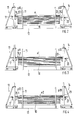
- the device consists of the two walking beam devices 13 and 14, which are mutually adjustable on the guideway 12.
- the walking beam devices 13 and 14 are moved up to the end faces of the stack 10 and can be locked on a guideway 12. In this way, the device can be quickly and easily adapted to different lengths of the section of the profile 10 which is stored in an unordered or ordered manner.
- the profile sections are housed in the container 11 which is retracted and locked between the walking beam devices 13 and 14.
- the ends of the profile sections protrude about 200 mm from the container, which can be a simple frame construction.
- the walking beam devices 13 and 14 each have a walking beam 17 or 22, which is driven, for example, by a spindle and an electric motor which is electronically infinitely variable in speed, as the drives 16 and 21 indicate.
- Each walking beam 17 or 22 has a slide 25.1 or 25.2 with a conveyor 18 or 22, which is controlled by a pneumatic or hydraulic piston-cylinder unit 19 or 24, so that the slide 10 in the longitudinal direction of the stack 25.1 or 25.2 can be adjusted together with the associated conveyor 18 or 23. With the slider 25.1 or 25.2, part of the profile sections lying at the top in the stack 10 can be moved in the longitudinal direction.
- the conveying direction of the conveying device 18 or 23 is oriented transversely to the longitudinal direction of the stack 10.
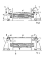
- the two walking beam devices 13 and 14 are in their end positions, i.e. they take the maximum distance.
- the walking beams 17 and 22 are brought to the uppermost position on the vertical frames 15 and 20.
- the slides 25.1 and 25.2 with the conveyors 18 and 23 are retracted, i.e. take the end positions facing away from the stack 10.
- the container 11 with the disordered or ordered profile sections is inserted and locked between the walking beam devices 13 and 14.
- the walking beam devices 13 and 14 are moved up to the end faces of the stack 10 and locked.
- the device is then in the starting position for the automatically unstacking process, which is initiated manually.
- each walking beam 17 and 22 descends to the frame 15 and 20 at high speed.
- Each walking beam 17 and 22 carries a transverse to the longitudinal direction of the Stack 10 directed light barrier, with which the top edge of the stack 10 is detected. This switches over to the slow speed of the drives 16 and 21, and the further adjustment of the walking beams 17 and 22 is detected and evaluated with rotary encoders.
- the walking beam 17 moves downwards until it is a predetermined amount below the top edge of the stack 10, which is only part of the maximum cross-sectional dimension of a profile section.
- the walking beam 22 is, however, lowered still further, namely by a path which is given by the sum of this predetermined amount and the maximum cross-sectional dimension of a profile section. These positions are designated p10 and p20 in FIG. 2.
- the device for unstacking a part e of profile sections that lies on top of the stack 10 is thus set.
- the slider 25.1 and the conveyor 18 of the walking beam 17 are then used to move part e of the profile sections.
- the position p11 shows the extended position of the slide 25.1 and conveyor 18.
- the displaced profile sections e1 are pushed onto the conveying device 23 which is still in the retracted initial position, as the position p20 shows.
- the walking beam 17 is lowered by an amount that is given by the maximum cross-sectional dimension of the profile sections.
- the walking beam 17 assumes the position p12 shown in FIG. 4, in which the slide 25.1 with the conveyor device 18 is also retracted into the starting position.
- the walking beam 22 of the walking beam device 14 is raised to the position p21 and the slide 25.2 with the conveyor 23 pushes on the profile sections e3 the conveyor 25.1 of the walking beam 17, which assumes the retracted position p12, as shown in FIG. 5. Then the walking beam 17 is brought to the same height with the walking beam 22 in slow motion. Finally, the profile sections e4 are brought into the uppermost positions p13 and p22, the adjustment starting in the slow gear and ending again in the slow gear via the overdrive. If the profile sections e4 have reached the position according to FIG.
- the conveying devices 18 and 23 are switched on, which forward the profile sections e4 to a slide or conveyor device, not shown, arranged on the side of the stack 10, via which they reach the material buffer of the processing machine. If the light barriers recognize that the profile sections e4 have left the conveying devices 18 and 23, then the slide 25.2 with the conveying device 23 is also returned to the retracted position. The device then assumes the initial rest position for a new unstacking process.
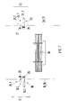
- FIG. 7 A modification of the unstacking device according to the invention and the associated method for operating the device is shown schematically in FIG. 7.
- the vertical frames 15 and 20 of the walking beam devices 13 and 14 and their drives 16 and 21 are indicated schematically by the vertical, dash-dotted lines.
- the lifting beams 17 and 22 are vertically adjustable on the frames 15 and 20.
- the walking beam 17 carries the slide 25.1 and the conveyor 18, while the walking beam 22 carries the slide 25.2 and the conveyor 23.
- the slides 25. 1 and 25.2 are each arranged at a small distance above the conveyors 18 and 23.
- Conveyors 18 and 23 may use endless conveyor belts 28 and 29 that extend more than the width of the stack 10.
- the slides 25.1 and 25.2 end facing the stack 10 in holding plates 26 and 27, the height of which only has to be slightly greater than the gripping height on the stack 10. In the drawing, they are shown much higher to show that their sides facing the stack 10 are provided with an elastic covering.
- These coverings can consist of rubber or an elastic plastic and are preferably exchangeably attached to rigid base plates which can be adjusted by means of the individually assigned actuating devices 19.1 and 19.2. This ensures that the end faces can more or less press into the holding plates 26 and 27, which is very important in the case of burr-provided end faces of the profile sections in order to unequivocally and securely grasp and hold the profile sections received by the holding plates 26 and 27
- the conveyor devices 18 and 23 are also assigned individual actuating devices 19.2 and 24.2, so that they can be adjusted independently of the slides 25.1 and 25.2.
- the slides 25.1 and 25.2 and the conveying devices 18 and 23 are in the highest position of the walking beams 17 and 22 on the frames 15 and 20 of the walking beam devices.
- the conveyor devices 18 and 23 with their conveyor belts 28 and 29 are located after the further slide or conveyor device.
- the slides 25.1 and 25.2 and the conveyors 18 and 23 are outside the stack 10.
- the walking beams 17 and 22 are lowered to such an extent that the holding plates 26 and 27 overlap the stack 10 by the predetermined gripping height, which depends on the cross section of the randomly stacked profile sections and comprises only part of the cross-sectional dimension.
- the actuators 19.1 and 24.1 move the slides 25.1 and 25.2 to the stack 10 simultaneously or in succession until the holding plates 26 and 27 grip the profile sections lying in the region of the gripping height.
- the elastic coverings of the holding plates 26 and 27 allow a different penetration depth for the profile sections, since, due to the burrs, the profile sections of the gripping height do not necessarily lie in a common plane and also cannot be aligned axially.
- the conveying devices 18 and 23 maintain their starting position.
- the gripped profile sections are lifted from the stack 10.
- the walking beams 17 and 22 are brought back into the highest position, so that the conveyors 18 and 23 assume their unloading position.
- the conveyors 18 and 23 were brought under the extended slides 25.1 and 25.2 by the actuators 19.2 and 24.2.
- the slides 25.1 and 25.2 are then returned to the starting position.
- the holding plates 26 and 27 release the profile sections so that their end sections lie on the endless conveyor belts 28 and 29 of the conveyors 18 and 23.
- the profile sections are passed on transversely to their longitudinal direction.
- the commissioning of the endless conveyor belts 28 and 29 can be done by one Requirement signal of the further conveyor or a processing station to be dependent. If all of the profile sections deposited on the conveying devices 18 and 23 are forwarded, then the actuating devices 19.2 and 24.2 also reset the conveying devices 18 and 23 back to their starting position, so that a new unstacking cycle can be initiated in which the walking beams 17 and 22 are again so far are lowered until they overlap the stack 10 with the holding plates 26 and 27 of the sliders 25.1 and 25.2 by the gripping height.
Abstract
Description
Die Erfindung betrifft eine Vorrichtung zum Entstapeln von länglichen Profilabschnitten eines Stapels mit einer auf einer Stirnseite des Stapels angeordneten Schiebeeinrichtung, die vertikal verstellbar ist und mit der nacheinander jeweils ein oben liegender Teil der Profilabschnitte des Stapels auf eine Stützeinrichtung schiebbar ist, die auf der gegenüberliegenden Seite des Stapels angeordnet und ebenfalls vertikal verstellbar ist, bei der die von der Schiebeeinrichtung verschobenen und von der Stützeinrichtung unterstützten Profilabschnitte vom Stapel abhebbar und mittels einer Transporteinrichtung quer zur Längsachse der Profilabschnitte weiterleitbar sind, sowie ein Verfahren zum Betreiben der Vorrichtung.The invention relates to a device for unstacking elongated profile sections of a stack with a sliding device arranged on one end face of the stack, which is vertically adjustable and with which an upper part of the profile sections of the stack can be pushed one after the other onto a support device which is on the opposite side of the stack is arranged and also vertically adjustable, in which the profile sections displaced by the sliding device and supported by the support device can be lifted off the stack and forwarded by means of a transport device transversely to the longitudinal axis of the profile sections, as well as a method for operating the device.
Eine Vorrichtung dieser Art ist durch die DE-PS 30 15 648 bekannt. Bei dieser Vorrichtung werden die Profilabschnitte in einem lagenweise geschichteten Stapel zugeführt. Dies erfordert aber entsprechend geordnete Stapel von Profilabschnitten, die zum einen teurer sind als ungeordnet zusammengebrachte und -gehaltene Profilabschnitte. Außerdem können nicht jede Profilabschnitte aufgrund ihrer unregelmäßigen Querschnitte in Lagen gestapelt werden.A device of this type is known from DE-PS 30 15 648. In this device, the profile sections are fed in a layered stack. However, this requires appropriately ordered stacks of profile sections, which on the one hand are more expensive than profile sections brought together and held in an unordered manner. In addition, not every profile section can be stacked in layers due to its irregular cross-sections.
Bei dieser bekannten Vorrichtung wird die oberste Lage von Profilabschnitten in Längsrichtung auf das Stützelement auf der gegenüberliegenden Seite des Stapels geschoben. Die so verschobenen Profilabschnitte können mit dem Stützelement angehoben werden, so daß quer zur Längsrichtung des Stapels verfahrbare Tragarme die so vorbereitete Lage von Profilabschnitten erfassen kann. Dazu wird das Stützelement an den erfaßten Profilabschnitten entlangbewegt, so daß diese auf ihrer gesamten Länge vom Stapel abgehoben werden, um die Tragarme einführen zu können. Die von den Tragarmen erfaßten Profilabschnitte werden auf eine Fördereinrichtung übergeben, die die Profilabschnitte einzeln in ihrer Längsrichtung weiterleitet. Das Beschicken der Fördereinrichtung, die senkrecht zu den Tragarmen verläuft, erfolgt durch stufenweises Verfahren der Tragarme. Die Tragarme mit ihrem Maschinengestell und ihrem Antrieb belegen mit der Fördereinrichtung neben dem Stapel einen Platz, der größer ist als die auf die Standfläche projizierte Fläche des Stapels, da die Tragarme ja eine Stapellage übernehmen und vereinzeln müssen. Außerdem ist die Vorrichtung sehr kompliziert und aufwendig und nicht schnell und leicht auf unterschiedliche Längen der Profilabschnitte einstellbar.In this known device, the uppermost layer of profile sections is placed on the support element in the longitudinal direction pushed the opposite side of the stack. The profile sections shifted in this way can be raised with the support element, so that support arms which can be moved transversely to the longitudinal direction of the stack can grasp the position of profile sections prepared in this way. For this purpose, the support element is moved along the detected profile sections so that they are lifted off the stack over their entire length in order to be able to insert the support arms. The profile sections gripped by the support arms are transferred to a conveying device which forwards the profile sections individually in their longitudinal direction. The conveyor, which is perpendicular to the support arms, is loaded by gradually moving the support arms. The support arms with their machine frame and their drive occupy with the conveyor next to the stack a space that is larger than the surface of the stack projected onto the standing surface, since the support arms have to take over and separate a stack position. In addition, the device is very complicated and expensive and not quickly and easily adjustable to different lengths of the profile sections.
Es ist Aufgabe der Erfindung, eine Vorrichtung der eingangs erwähnten Art zu schaffen, die einfach im Aufbau ist, auf unterschiedlich lange Profilabschnitte einstellbar ist und ungeordnete Stapel von Profilabschnitten entstapeln kann, sowie ein Verfahren zum Betreiben der Vorrichtung.It is an object of the invention to provide a device of the type mentioned at the outset, which is simple in construction, can be adjusted to profile sections of different lengths and can unstack unordered stacks of profile sections, and a method for operating the device.
Diese Aufgabe wird nach der Erfindung dadurch gelöst, daß die Schiebeeinrichtung und die Stützeinrichtung als Hubbalkengeräte ausgebildet sind, die in Längsrichtung des Stapels im Abstand zueinander verstellbar sind, daß die Profilabschnitte in einem Stapelbehälter abgelegt sind, der zwischen die beiden Hubbalkengeräte einbringbar ist, und daß jedes Hubbalkengerät einen Hubbalken mit einem in Längsrichtung der Profilabschnitte verstellbaren Schieber als Schiebeeinrichtung und ein quer zur Längsachse der Profilabschnitte verlaufende Fördereinrichtung aufweist.This object is achieved according to the invention in that the sliding device and the support device are designed as walking beam devices, which are adjustable in the longitudinal direction of the stack at a distance from each other, that the profile sections are stored in a stacking container, which is between the two Walking beam devices can be inserted, and that each walking beam device has a walking beam with a slide adjustable in the longitudinal direction of the profile sections as a sliding device and a conveyor device running transversely to the longitudinal axis of the profile sections.
Die Ausbildung der Vorrichtung mit zwei verfahrbaren Hubbalkengeräten hat den Vorteil, daß eine einfache Anpassung an verschiedene Längen von Profilabschnitten möglich ist. Die Hubbalken vereinigen eine Schiebeeinrichtung und eine Fördereinrichtung, so daß die für das Entstapeln erforderlichen Verschiebe-, Hebe- und Förderbewegungen einfach zu steuern sind. Die Vorrichtung erfordert zum Entstapeln nur die beiden Hubbalkengeräte, die an den Stirnseiten des Stapels angeordnet sind, und kann zum Entstapeln eines geordneten und ungeordneten Stapels verwendet werden.The design of the device with two movable walking beam devices has the advantage that simple adaptation to different lengths of profile sections is possible. The walking beams combine a pushing device and a conveying device, so that the shifting, lifting and conveying movements required for unstacking are easy to control. For unstacking, the device only requires the two walking beam devices, which are arranged on the end faces of the stack, and can be used for unstacking an ordered and disordered stack.
Für die Einstellung der Hubbalken bei den Entstapelungsvorgängen werden einfach dadurch Bezugspunkte geschaffen, daß jeder Hubbalken eine quer zur Längsrichtung des Stapels verlaufende Lichtschranke aufweist, mit der die höchste Kante des Stapels erfaßbar ist. Diese Bezugspunkte wandern mit der fortschreitenden Entstapelung des Stapels.For the setting of the walking beams during the unstacking operations, reference points are created simply in that each walking beam has a light barrier which runs transversely to the longitudinal direction of the stack and by means of which the highest edge of the stack can be detected. These reference points move with the progressive unstacking of the stack.
Die Vertikalverstellung der Hubbalken wird nach einer Ausgestaltung dadurch erhalten, daß die Hubbalken mittels eines elektronisch stufenlos regelbaren elektromotorischen Antriebes in einem Schnellgang und einem Langsamgang an einem vertikalen Rahmen verstellbar sind.According to one embodiment, the vertical adjustment of the walking beams is obtained in that the walking beams can be adjusted in a high speed and a slow speed on a vertical frame by means of an electronically infinitely variable electric motor drive.
Nach einer Ausgestaltung ist vorgesehen, daß die Schieber zusammen mit den Fördereinrichtungen in Längsrichtung des Stapels verstellbar an dem Hubbalken angebracht sind.According to one embodiment, it is provided that the slides are attached to the walking beam in an adjustable manner in the longitudinal direction of the stack.
Für die Steuerung der Schieber sieht eine weitere Ausgestaltung vor, daß die Schieber mit den Fördereinrichtungen jeweils mittels einer pneumatischen oder hydraulischen Kolben-Zylinder-Einheit verstellbar sind.For the control of the slide, a further embodiment provides that the slide with the conveying devices can each be adjusted by means of a pneumatic or hydraulic piston-cylinder unit.
Damit beim Verschieben der Profilabschnitte keine Blockierung auftritt, ist das Verfahren zum Betreiben der Vorrichtung so, daß zu Beginn eines Entstapelvorganges der ei ne Schieber um einen vorgegebenen Betrag gegenüber der obersten Kante des Stapels abgesenkt wird, der nur einem Teil der maximalen Querschnittsabmessung eines Profilabschnittes entspricht, und daß die als Stützeinrichtung verwendete Fördereinrichtung auf der gegenüberliegenden Stirnseite des Stapels auf eine Höhe eingestellt wird, die um den vorgegebenen Betrag plus der maximalen Querschnittsabmessung unter der höchsten Kante des Stapels liegt.So that no blockage occurs when moving the profile sections, the method for operating the device is such that at the beginning of an unstacking process, the slider is lowered by a predetermined amount relative to the top edge of the stack, which corresponds only to part of the maximum cross-sectional dimension of a profile section , and that the conveyor used as a support device is set on the opposite end of the stack to a height which is below the highest edge of the stack by the predetermined amount plus the maximum cross-sectional dimension.
Der weitere Ablauf der Entstapelung ist nach dem Verfahren so festgelegt, daß für weitere Entstapelungsvorgänge der eine Schieber und die gegenüberliegende Fördereinrichtung jeweils um die maximale Querschnittsabmessung eines Profilabschnittes abgesenkt werden.The further process of unstacking is determined according to the method in such a way that for further unstacking operations the one slide and the opposite conveying device are each lowered by the maximum cross-sectional dimension of a profile section.
Das Verfahren des Entstapelungsvorganges wird dadurch vervollständigt, daß die von der Fördereinrichtung erfaßten Profilabschnitte durch eine Verstellung des zugeordneten Hubbalkens vom Stapel abgehoben und mittels des zugeordneten Schiebers auf die Fördereinrichtung der entgegengesetzten Seite zurückgeschoben werden, die vorher aus der Ausgangsstellung zu Beginn des Entstapelungsvorganges um die maximale Querschnittsabmessung eines Profilstranges abgesenkt worden ist, sowie daß die von den Fördereinrichtungen getragenen Profilabschnitte in die höchste Stellung der Hubbalkengeräte angehoben und durch die Fördereinrichtungen auf eine seitlich des Stapels angeordnete Rutsche oder Fördereinrichtung weitergeleitet werden.The process of the unstacking process is completed in that the profile sections detected by the conveying device are lifted from the stack by an adjustment of the associated lifting beam and pushed back to the conveying device on the opposite side by means of the associated pusher, which previously had the maximum from the initial position at the beginning of the unstacking process Cross-sectional dimension of a profile strand has been lowered, and that the profile sections carried by the conveyors are raised to the highest position of the walking beam devices and laterally by the conveyors arranged stack or conveyor are forwarded.
Die Vorrichtung kann nach einer Abwandlung auch so ausgelegt sein, daß jedem Schieber und jeder Fördereinrichtung eine individuelle Stelleinrichtung zugeordnet ist und daß die Fördereinrichtungen jeweils unterhalb des zugeordneten Schiebers auf dem Hubbalken angeordnet sind.According to a modification, the device can also be designed in such a way that each slide and each conveying device is assigned an individual actuating device and that the conveying devices are each arranged below the assigned slide on the walking beam.
Das Verfahren zum Betreiben dieser Vorrichtung ist dann dadurch gekennzeichnet, daß zu Beginn eines Entstapelungsvorganges die Schieber durch ihre Stelleinrichtungen in eine Ausgangsstellung außerhalb des Stapels eingestellt werden, daß die Hubbalken und damit die Schieber durch die Antriebe der Hubbalkengeräte in eine Greifstellung zum Stapel eingestellt werden, in der jeweils die obersten Profilabschnitte des Stapels festlegbar sind, daß die Schieber durch ihre Stelleinrichtungen gleichzeitig oder nacheinander an den Stapel herangeführt werden, um mit Halteplatten die in Greifstellung befindlichen Profilabschnitte stirnseitig zu fassen, daß die gefaßten Profilabschnitte durch Anheben der Hubbalken vom Stapel abgehoben werden, daß die Fördereinrichtungen durch ihre Stelleinrichtungen unter die Schieber verstellt werden, daß die Schieber durch ihre Stelleinrichtungen in die Ausgangsstellung zurückgestellt werden, wobei die abgehobenen Profilabschnitte auf die darunter bereitstehenden Fördereinrichtungen abgegeben werden, daß durch die Fördereinrichtungen die erhaltenen Profilabschnitte seitlich abtransportiert werden und daß nach der Entleerung die Fördereinrichtungen durch ihre Stelleinrichtungen in ihre Ausgangsstellung zurückgestellt werden. Dabei ist wieder zur störungsfreien, vereinzelten Weiterleitung der Profilabschnitte vorgesehen, daß die Hubbalken beim Abheben vom Stapel jeweils in die höchste Stellung der Hubbalkengeräte hochgefahren werden, in der die Fördereinrichtungen an die weiterführende Rutsche oder Fördereinrichtung anschließen.The method for operating this device is then characterized in that at the beginning of a de-stacking process, the slides are set into an initial position outside the stack by their actuating devices, that the walking beams and thus the slides are set in a gripping position to the stack by the drives of the walking beam devices, in each of which the uppermost profile sections of the stack can be determined that the slides are brought to the stack simultaneously or one after the other by their adjusting devices in order to grasp the profile sections in the gripping position on the front side with holding plates, that the gripped profile sections are lifted off the stack by lifting the walking beams that the conveyors are adjusted by their adjusting devices under the slider, that the slider are returned to their starting position by their adjusting devices, with the profile sections lifted to the area below standing conveying devices are delivered that the profile sections obtained are removed laterally by the conveying devices and that after the emptying the conveying devices are returned to their starting position by their actuating devices. It is back to Trouble-free, isolated forwarding of the profile sections provided that the lifting beams are raised to the highest position of the walking beam devices when they are lifted from the stack, in which the conveying devices connect to the further slide or conveying device.
Da die Profilabschnitte in der Regel aus einem Profilstrang abgelängt sind, ergeben sich an den Stirnseiten mehr oder weniger starke Grate, die ein axiales Verstellen der Profilabschnitte beim Fassen durch die Schieber stark behindern können, was zu einem unsicheren Fassen und Abheben der Profilabschnitte und damit zur Störung beim Betreiben der Vorrichtung führen kann. Um dies zu vermeiden, sieht eine weitere Ausgestaltung der Vorrichtung vor, daß die Schieber in Halteplatten auslaufen, die auf den dem Stapel zugekehrten Seiten mit einem elastischen Belag, z.B. aus Gummi, elastischem Kunststoff oder dgl., abgeschlossen sind.Since the profile sections are usually cut to length from a profile strand, there are more or less strong burrs on the end faces, which can hinder an axial adjustment of the profile sections when gripping by the slide, which leads to unsafe gripping and lifting of the profile sections and thus Malfunction when operating the device can result. In order to avoid this, a further embodiment of the device provides that the slides run out in holding plates which are coated on the sides facing the stack with an elastic covering, e.g. made of rubber, elastic plastic or the like.
Der elastische Belag läßt einen Längenausgleich zu, da sich die Profilabschnitte mit ihren Stirnseiten unterschiedlich tief in diesem Belag eindrücken können. Es hat sich gezeigt, daß allein durch diese Maßnahme ein sicheres Fassen und Abheben auch von Profilabschnitten mit mehr oder weniger starken Graten an den Stirnseiten erreichen läßt.The elastic covering allows length compensation, since the profile sections with their end faces can be pressed into this covering to different depths. It has been shown that this measure alone can be used to reliably grasp and lift profile sections with more or less strong burrs on the end faces.
Ist dazu noch vorgesehen, daß der Belag auswechselbar an einer starren Grundplatte befestigt ist, dann können diese dem Verschleiß unterliegenden Teile der Schieber schnell ausgetauscht und durch neue Beläge ersetzt werden.If it is also provided that the covering is exchangeably fastened to a rigid base plate, then these parts of the slide which are subject to wear can be quickly replaced and replaced by new coverings.
Die Erfindung wird anhand eines in den Zeichnungen dargestellten Ausführungsbeispiels näher erläutert. Es zeigt:
- Fig. 1
- eine Entstapelungs-Vorrichtung nach der Erfindung in Seitenansicht mit gemeinsamer Verstellung von Schieber und Fördereinrichtung,
- Fig. 2 bis 6
- schematisch die einzelnen Stufen eines Entstapelungs-Vorganges in vereinfachter Seitenansicht, und
- Fig. 7
- in schematischer Darstellung eine Entstapelungs-Vorrichtung nach der Erfindung mit individueller Verstellung von Schieber und Fördereinrichtung.
- Fig. 1
- FIG. 2 shows a de-stacking device according to the invention in a side view with a common adjustment of the slide and the conveying device,
- 2 to 6
- schematically the individual stages of a denesting process in a simplified side view, and
- Fig. 7
- a schematic representation of a de-stacking device according to the invention with individual adjustment of the slide and conveyor.
Wie die Fig. 1 zeigt, besteht die Vorrichtung aus den beiden Hubbalkengeräten 13 und 14, die auf der Führungsbahn 12 gegeneinander verstellbar sind. Die Hubbalkengeräte 13 und 14 werden an die Stirnseiten des Stapels 10 herangefahren und können auf einer Führungsbahn 12 arretiert werden. Auf diese Weise kann die Vorrichtung schnell und leicht an unterschiedliche Längen der im Stapel 10 ungeordnet oder geordnet abgelegten Profilabschnitte angepaßt werden. Die Profilabschnitte sind in dem Behälter 11 untergebracht, der zwischen die Hubbalkengeräte 13 und 14 eingefahren und arretiert wird. Die Enden der Profilabschnitte stehen dabei etwa 200 mm aus dem Behälter vor, der eine einfache Rahmenkonstruktion sein kann.1 shows, the device consists of the two
Die Hubbalkengeräte 13 und 14 haben jeweils einen Hubbalken 17 bzw. 22, der z.B. über eine Spindel und einen in der Drehzahl elektronisch stufenlos regelbaren Elektromotor angetrieben wird, wie die Antriebe 16 und 21 andeuten.The
Jeder Hubbalken 17 bzw. 22 weist einen Schieber 25.1 bzw. 25.2 mit einer Fördereinrichtung 18 bzw. 22 auf, der von einer pneumatischen oder hydraulischen Kolben-Zylinder-Einheit 19 bzw. 24 gesteuert wird, so daß in Längsrichtung des Stapels 10 jeweils der Schieber 25.1 bzw. 25.2 mit der zugeordneten Fördereinrichtung 18 bzw. 23 gemeinsam verstellt werden. Mit dem Schieber 25.1 bzw. 25.2 kann ein Teil der oben im Stapel 10 liegenden Profilabschnitte in der Längsrichtung verschoben werden. Die Förderrichtung der Fördereinrichtung 18 bzw. 23 ist quer zur Längsrichtung des Stapels 10 ausgerichtet.Each
Anhand der Fig. 2 bis 6 wird die Arbeitsweise der Vorrichtung näher erläutert.The operation of the device is explained in more detail with reference to FIGS. 2 to 6.
In der Ausgangsruhestellung sind die beiden Hubbalkengeräte 13 und 14 in ihren Endstellungen, d.h. sie nehmen den maximalen Abstand ein. Die Hubbalken 17 und 22 sind an den vertikalen Rahmen 15 und 20 in die oberste Stellung gebracht. Die Schieber 25.1 und 25.2 mit den Fördereinrichtungen 18 und 23 sind zurückgezogen, d.h. nehmen die dem Stapel 10 abgekehrten Endstellungen ein. In dieser Ausgangsruhestellung wird der Behälter 11 mit den ungeordnet oder geordnet abgelegten Profilabschnitten zwischen die Hubbalkengeräte 13 und 14 eingefahren und arretiert. Die Hubbalkengeräte 13 und 14 werden an die Stirnseiten des Stapels 10 herangefahren und arretiert. Die Vorrichtung befindet sich dann in der Ausgangsstellung für den automatisch ablaufenden Entstapelungs-Vorgang, der manuell eingeleitet wird.In the initial rest position, the two
Mit der Inbetriebnahme der Vorrichtung fahren die Hubbalken 17 und 22 im Schnellgang an den Rahmen 15 und 20 herab. Jeder Hubbalken 17 und 22 trägt eine quer zur Längsrichtung des Stapels 10 gerichtete Lichtschranke, mit der die oberste Kante des Stapels 10 erfaßt wird. Damit wird auf den Langsamgang der Antriebe 16 und 21 umgeschaltet und mit Drehimpulsgebern die weitere Verstellung der Hubbalken 17 und 22 erfaßt und ausgewertet. Der Hubbalken 17 fährt soweit nach unten, bis er einen vorgegebenen Betrag unterhalb der obersten Kante des Stapels 10 steht, der nur einen Teil der maximalen Querschnittsabmessung eines Profilabschnittes beträgt. Der Hubbalken 22 wird jedoch noch weiter abgesenkt und zwar um einen Weg, der durch die Summe aus diesem vorgegebenen Betrag und der maximalen Querschnittsabmessung eines Profilabschnittes gegeben ist. Diese Stellungen sind in Fig. 2 mit p10 und p20 bezeichnet . Damit ist die Vorrichtung zum Entstapeln eines Teils e von Profilabschnitten eingestellt, der am Stapel 10 oben liegt.When the device is started up, the
Wie Fig. 3 zeigt, wird dann mit dem Schieber 25.1 und der Fördereinrichtung 18 des Hubbalkens 17 der Teil e der Profilabschnitte verschoben. Die Stellung p11 zeigt die ausgefahrene Stellung von Schieber 25.1 und Fördereinrichtung 18 an. Beim Hubbalken 22 werden die verschobenen Profilabschnitte e1 auf die noch in der eingezogenen Ausgangsstellung befindliche Fördereinrichtung 23 geschoben, wie die Stellung p20 zeigt. Im folgenden Takt des Entstapelungs-Vorganges wird der Hubbalken 17 um einen Betrag abgesenkt, der durch die maximale Querschnittsabmessung der Profilabschnitte gegeben ist. Der Hubbalken 17 nimmt die in Fig. 4 gezeigte Position p12 ein, in der auch der Schieber 25.1 mit der Fördereinrichtung 18 wieder in die Ausgangsstellung eingezogen ist. Der Hubbalken 22 des Hubbalkengerätes 14 wird in die Stellung p21 hochgefahren und der Schieber 25.2 mit der Fördereinrichtung 23 schiebt die Profilabschnitte e3 auf die Fördereinrichtung 25.1 des Hubbalkens 17, die die eingezogene Position p12 einnimmt, wie Fig. 5 zeigt. Dann wird der Hubbalken 17 im Langsamgang auf gleiche Höhe mit dem Hubbalken 22 gebracht. Schließlich werden die Profilabschnitte e4 in die obersten Stellungen p13 und p22 gebracht, wobei die Verstellung im Langsamgang anfängt und über den Schnellgang wieder im Langsamgang ausläuft. Haben die Profilabschnitte e4 die Stellung nach Fig. 6 erreicht, dann werden die Fördereinrichtungen 18 und 23 eingeschaltet, die die Profilabschnitte e4 auf eine seitlich des Stapels 10 angeordnete, nicht dargestellte Rutsche oder Fördereinrichtung weiterleiten, über die sie in den Materialpuffer der Verarbeitungsmaschine gelangen. Erkennen die Lichtschranken, daß die Profilabschnitte e4 die Fördereinrichtungen 18 und 23 verlassen haben, dann wird auch der Schieber 25.2 mit der Fördereinrichtung 23 in die eingezogene Stellung zurückgestellt. Die Vorrichtung nimmt dann die Ausgangsruhestellung für einen neuen Entstapelungs-Vorgang ein.As shown in FIG. 3, the slider 25.1 and the
Eine Abwandlung der Entstapelungs-Vorrichtung nach der Erfindung und das dazugehörige Verfahren zum Betreiben der Vorrichtung ist in Fig. 7 schematisch dargestellt. Die vertikalen Rahmen 15 und 20 der Hubbalkengeräte 13 und 14 und ihre Antriebe 16 und 21 sind schematisch durch die vertikalen, strichpunktierten Linien angegeben. An den Rahmen 15 und 20 sind die Hubbalken 17 und 22 vertikal verstellbar.A modification of the unstacking device according to the invention and the associated method for operating the device is shown schematically in FIG. 7. The
Der Hubbalken 17 trägt den Schieber 25.1 und die Fördereinrichtung 18, während der Hubbalken 22 den Schieber 25.2 und die Fördereinrichtung 23 trägt. Die Schieber 25. 1 und 25.2 sind jeweils in einem kleinen Abstand über den Fördereinrichtungen 18 und 23 angeordnet. Als Fördereinrichtungen 18 und 23 können Endlos-Förderbänder 28 und 29 verwendet werden, die sich über mehr als die Breite des Stapels 10 erstrecken. Die Schieber 25.1 und 25.2 enden dem Stapel 10 zugekehrt in Halteplatten 26 und 27, deren Höhe nur geringfügig größer sein muß als die Greifhöhe am Stapel 10. In der Zeichnung sind sie wesentlich höher dargestellt, um zu zeigen, daß ihre dem Stapel 10 zugekehrten Seiten mit einem elastischen Belag versehen sind. Diese Beläge können aus Gummi oder einem elastischen Kunststoff bestehen und sind vorzugsweise austauschbar an starren Grundplatten befestigt, die mittels der individuell zugeordenten Stelleinrichtungen 19.1 und 19.2 verstellt werden können. Damit wird erreicht, daß sich die Stirnseiten mehr oder weniger in die Halteplatten 26 und 27 eindrücken können, was bei mit Graten versehenen Stirnseiten der Profilabschnitte sehr wichtig ist, um ein eindeutiges und sicheres Fassen und Halten der von den Halteplatten 26 und 27 aufgenommenen Profilabschnitte zu gewährleisten.The
Den Fördereinrichtungen 18 und 23 sind ebenfalls individuelle Stelleinrichtungen 19.2 und 24.2 zugeordnet, so daß sie unabhängig von den Schiebern 25.1 und 25.2 verstellt werden können.The
In der schematisch dargestellten Ausgangsstellung befinden sich die Schieber 25.1 und 25.2 sowie die Fördereinrichtungen 18 und 23 in der höchsten Stellung der Hubbalken 17 und 22 an den Rahmen 15 und 20 der Hubbalkengeräte. In dieser Ausgangsstellung befinden sich die Fördereinrichtungen 18 und 23 mit ihren Förderbändern 28 und 29 im Anschluß an die weiterführende Rutsche oder Fördereinrichtung. Außerdem stehen die Schieber 25.1 und 25.2 sowie die Fördereinrichtungen 18 und 23 außerhalb des Stapels 10.In the schematically illustrated starting position, the slides 25.1 and 25.2 and the conveying
Zum Betreiben dieser Vorrichtung werden die Hubbalken 17 und 22 soweit abgesenkt, daß die Halteplatten 26 und 27 den Stapel 10 um die vorgegebene Greifhöhe überlappen, die vom Querschnitt der ungeordnet gestapelten Profilabschnitte abhängt und nur einen Teil der Querschnittsabmessung umfaßt. Dann werden durch die Stelleinrichtungen 19.1 und 24.1 die Schieber 25.1 und 25.2 gleichzeitig oder nacheinander an den Stapel 10 herangeführt, bis die Halteplatten 26 und 27 die im Bereich der Greifhöhe liegenden Profilabschnitte fassen. Die elastischen Beläge der Halteplatten 26 und 27 lassen dabei eine unterschiedliche Eindringtiefe für die Profilabschnitte zu, da infolge der Grate die Profilabschnitte der Greifhöhe nicht unbedingt in einer gemeinsamen Ebene liegen und auch axial nicht ausgerichtet werden können. Beim Fassen der Profilabschnitte durch die Halteplatten 26 und 27 der Schieber 25.1 und 25.2 behalten die Fördereinrichtungen 18 und 23 ihre Ausgangsstellung bei. Durch Anheben der Hubbalken 17 und 22 werden die gefaßten Profilabschnitte vom Stapel 10 abgehoben. Die Hubbalken 17 und 22 werden wieder in die höchste Stellung gebracht, so daß die Fördereinrichtungen 18 und 23 ihre Entladestellung einnehmen. Vorher wurden die Fördereinrichtungen 18 und 23 jedoch durch die Stelleinrichtungen 19.2 und 24.2 unter die ausgefahrenen Schieber 25.1 und 25.2 gebracht. Danach werden die Schieber 25.1 und 25.2 in die Ausgangsstellung zurückgestellt. Dabei geben die Halteplatten 26 und 27 die Profilabschnitte frei, so daß sie mit ihren Endabschnitten auf den Endlos-Förderbändern 28 und 29 der Fördereinrichtungen 18 und 23 liegen. Werden die Endlos-Förderbänder 28 und 29 in Betrieb gesetzt, dann werden die Profilabschnitte quer zu ihrer Längsrichtung weitergeleitet. Die Inbetriebnahme der Endlos-Förderbänder 28 und 29 kann dabei von einem Anforderungssignal der weiterführenden Fördereinrichtung oder einer Weiterbearbeitungsstation abhängig sein. Sind alle auf die Fördereinrichtungen 18 und 23 abgelegten Profilabschnitte weitergeleitet, dann stellen die Stelleinrichtungen 19.2 und 24.2 auch die Fördereinrichtungen 18 und 23 wieder in ihre Ausgangsstellung zurück, so daß ein neuer Entstapelungszyklus eingeleitet werden kann, bei dem die Hubbalken 17 und 22 wieder so weit abgesenkt werden, bis sie den Stapel 10 mit den Halteplatten 26 und 27 der Schieber 25.1 und 25.2 um die Greifhöhe überlappen.To operate this device, the walking beams 17 and 22 are lowered to such an extent that the holding
Claims (14)
dadurch gekennzeichnet,
daß die Schiebeeinrichtung und die Stützeinrichtung als Hubbalkengeräte (13,14) ausgebildet sind, die in Längsrichtung des Stapels (10) im Abstand zueinander verstellbar sind,
daß die Profilabschnitte in einem Stapelbehälter (11) abgelegt sind, der zwischen die beiden Hubbalkengeräte (13,14) einbringbar ist, und
daß jedes Hubbalkengerät einen Hubbalken (17,22) mit einem in Längsrichtung der Profilabschnitte verstellbaren Schieber (25.1; 25.2) und eine quer zur Längsachse der Profilabschnitte verlaufende Fördereinrichtung (18,23) aufweist.Device for unstacking elongated profile sections of a stack with a sliding device arranged on one end face of the stack, which is vertically adjustable and with which an overhead part of the profile sections of the stack can be pushed onto a support device which is arranged on the opposite side of the stack and is also vertically adjustable, in which the profile sections displaced by the sliding device and supported by the support device can be lifted off the stack and can be passed on transversely to the longitudinal axis of the profile sections by means of a transport device,
characterized,
that the sliding device and the supporting device are designed as walking beam devices (13, 14) which can be adjusted at a distance from one another in the longitudinal direction of the stack (10),
that the profile sections are stored in a stacking container (11) which can be inserted between the two walking beam devices (13, 14), and
that each walking beam device has a walking beam (17,22) with a slide (25.1; 25.2) adjustable in the longitudinal direction of the profile sections and a conveyor (18,23) running transversely to the longitudinal axis of the profile sections.
dadurch gekennzeichnet,
daß jeder Hubbalken (17,22) eine quer zur Längsrichtung des Stapels (10) verlaufende Lichtschranke aufweist, mit der die höchste Kante des Stapels (10) erfaßbar ist.Device according to claim 1,
characterized,
that each walking beam (17, 22) has a light barrier running transversely to the longitudinal direction of the stack (10), with which the highest edge of the stack (10) can be detected.
dadurch gekennzeichnet,
daß die Hubbalken (17,22) mittels eines elektronisch, stufenlos regelbaren elektromotorischen Antriebes (16,21) in einem Schnellgang und einem Langsamgang an einem vertikalen Rahmen (15,20) verstellbar sind.Device according to claim 1 or 2,
characterized,
that the walking beams (17,22) can be adjusted in an overdrive and a slow gear on a vertical frame (15, 20) by means of an electronically, continuously variable electric motor drive (16, 21).
dadurch gekennzeichnet,
daß die Schieber (25.1; 25.2) zusammen mit den Fördereinrichtungen (18,23) in Längsrichtung des Stapels (10) verstellbar an dem Hubbalken (17,22) angebracht sind.Device according to one of claims 1 to 3,
characterized,
that the slider (25.1; 25.2) together with the conveying devices (18, 23) in the longitudinal direction of the stack (10) are adjustably attached to the walking beam (17, 22).
dadurch gekennzeichnet,
daß die Schieber (25.1; 25.2) mit den Fördereinrichtungen (18,23) jeweils mittels einer pneumatischen oder hydraulischen Kolben-Zylinder-Einheit (19,24) verstellbar sind.Device according to one of claims 1 to 4,
characterized,
that the slide (25.1; 25.2) with the conveying devices (18, 23) can each be adjusted by means of a pneumatic or hydraulic piston-cylinder unit (19, 24).
dadurch gekennzeichnet,
daß jedem Schieber (25.1; 25.2) und jeder Fördereinrichtung (18,23) eine individuelle Stelleinrichtung (19.1; 24.1; 19.2; 24.2) zugeordnet ist und
daß die Fördereinrichtungen (18,23) jeweils unterhalb des zugeordneten Schiebers (25.1; 25.2) auf dem Hubbalken (17,22) angeordnet sind.Device according to claim 1,
characterized,
that each slide (25.1; 25.2) and each conveyor (18,23) is assigned an individual actuating device (19.1; 24.1; 19.2; 24.2) and
that the conveyor devices (18, 23) are each arranged below the assigned slide (25.1; 25.2) on the walking beam (17.22).
dadurch gekennzeichnet,
daß die Schieber (19,24, 19.1,24.1, 19.2,24.2) in Halteplatten (26,27) auslaufen, die auf den dem Stapel (10) zugekehrten Seiten mit einem elastischen Belag, z.B. aus Gummi, elastischem Kunststoff oder dgl., abgeschlossen sind.Device according to one of claims 1 to 6,
characterized,
that the slides (19, 24, 19.1, 24.1, 19.2, 24.2) end in holding plates (26, 27) which, on the sides facing the stack (10), have an elastic covering, for example made of rubber, elastic plastic or the like, Are completed.
dadurch gekennzeichnet,
daß der Belag auswechselbar an einer starren Grundpaltte befestigt ist.Device according to claim 7,
characterized,
that the covering is interchangeably attached to a rigid base.
dadurch gekennzeichnet,
daß zu Beginn eines Entstapelvorganges der eine Schieber (25.1) um einen vorgegebenen Betrag gegenüber der obersten Kante des Stapels (10) abgesenkt wird, der nur einem Teil der maximalen Querschnittsabmessung eines Profilabschnittes entspricht, und
daß die als Stützeinrichtung verwendete Fördereinrichtung (23) auf der gegenüberliegenden Stirnseite des Stapels (10) auf eine Höhe eingestellt wird, die um den vorgegebenen Betrag plus der maximalen Querschnittsabmessung unter der höchsten Kante des Stapels (10) liegt (Fig. 2).Method for operating a device according to one of claims 1 to 5,
characterized,
that at the beginning of an unstacking process, a slide (25.1) is lowered by a predetermined amount relative to the top edge of the stack (10), which corresponds to only part of the maximum cross-sectional dimension of a profile section, and
that the conveyor device (23) used as a support device on the opposite end face of the stack (10) is set to a height which is below the highest edge of the stack (10) by the predetermined amount plus the maximum cross-sectional dimension (FIG. 2).
dadurch gekennzeichnet,
daß für weitere Entstapelungsvorgänge der eine Schieber (25.1) und die gegenüberliegende Fördereinrichtung (23) jeweils um die maximale Querschnittsabmessung eines Profilabschnittes abgesenkt wird.Method according to claim 9,
characterized,
that for further unstacking operations the one slide (25.1) and the opposite conveyor (23) are each lowered by the maximum cross-sectional dimension of a profile section.
dadurch gekennzeichnet,
daß die von der Fördereinrichtung (23) erfaßten Profilabschnitte (e2) durch eine Verstellung des zugeordneten Hubbalkens (22) vom Stapel (10) abgehoben und mittels des zugeordneten Schiebers (25.2) auf die Fördereinrichtung (18) der entgegengesetzten Seite zurückgeschoben werden, die vorher aus der Ausgangsstellung zu Beginn des Entstapelungsvorganges um die maximale Querschnittsabmessung eines Profilstranges abgesenkt worden ist (Fig. 4 und 5).A method according to claim 9 or 10,
characterized,
that the profile sections (e2) detected by the conveyor (23) are lifted from the stack (10) by an adjustment of the associated lifting beam (22) and pushed back onto the conveyor (18) on the opposite side by means of the associated slide (25.2), which previously has been lowered from the initial position at the beginning of the denesting process by the maximum cross-sectional dimension of a profile strand (FIGS. 4 and 5).
dadurch gekennzeichnet,
daß die von den Fördereinrichtungen (18,23) getragenen Profilabschnitte (e3, e4) in die höchste Stellung der Hubbalkengeräte (13,14) angehoben und durch die Fördereinrichtungen (18,23) auf eine seitlich des Stapels (10) angeordnete Rutsche oder Fördereinrichtung weitergeleitet werden.Method according to one of claims 9 to 11,
characterized,
that the profile sections (e3, e4) carried by the conveyor devices (18, 23) are raised to the highest position of the walking beam devices (13, 14) and by the conveyor devices (18, 23) on a slide or conveyor device arranged to the side of the stack (10) to get redirected.
daß zu Beginn eines Entstapelungsvorganges die Schieber (25.1, 25.2) durch ihre Stelleinrichtungen (19.1, 24.1) in eine Ausgangsstellung außerhalb des Stapels (10) eingestellt werden,
daß die Hubbalken (17,22) und damit die Schieber (25.1, 25.2) durch die Antriebe (16,21) der Hubbalkengeräte (13,14) in eine Greifstellung zum Stapel (10) eingestellt werden, in der jeweils die obersten Profilabschnitte des Stapels (10) faßbar sind,
daß die Schieber (25.1, 25.2) durch ihre Stelleinrichtungen (19.1, 24.1) gleichzeitig oder nacheinander an den Stapel (10) herangeführt werden, um mit Halteplatten (26,27) die in Greifstellung befindlichen Profilabschnitte stirnseitig zu fassen,
daß die gefaßten Profilabschnitte durch Anheben der Hubbalken (17,22) vom Stapel (10) abgehoben werden, daß die Fördereinrichtungen (18,23) durch ihre Stelleinrichtungen (19.2, 24.2) unter die Schieber (25.1, 25.2) verstellt werden,
daß die Schieber (25.1, 25.2) durch ihre Stelleinrichtungen (19.2, 24.1) in die Ausgangsstellung zurückgestellt werden, wobei die abgehobenen Profilabschnitte auf die darunter bereitstehenden Fördereinrichtungen (18,23) abgegeben werden,
daß durch die Fördereinrichtungen (18,23) die erhaltenen Profilabschnitte seitlich abtransportiert werden, und daß nach der Entleerung die Fördereinrichtungen (18,23) durch ihre Stelleinrichtungen (19.2, 24.2) in ihre Ausgangsstellung zurückgestellt werden.Method for operating the device according to claims 1 and 6, characterized in that
that at the beginning of an unstacking process, the slides (25.1, 25.2) are set into an initial position outside the stack (10) by their adjusting devices (19.1, 24.1),
that the walking beam (17,22) and thus the slider (25.1, 25.2) are set by the drives (16,21) of the walking beam devices (13,14) in a gripping position to the stack (10), in which the uppermost profile sections of the Stack (10) are graspable,
that the slides (25.1, 25.2) are moved by their actuating devices (19.1, 24.1) simultaneously or in succession to the stack (10) in order to hold the profile sections in the gripping position on the end face with holding plates (26,27),
that the gripped profile sections are lifted from the stack (10) by lifting the walking beams (17,22), that the conveying devices (18,23) are adjusted by the actuating devices (19.2, 24.2) under the slide (25.1, 25.2),
that the slides (25.1, 25.2) are returned to their starting position by their adjusting devices (19.2, 24.1), the lifted profile sections being delivered to the conveying devices (18, 23) provided below,
that the profile sections obtained are removed laterally by the conveyor devices (18, 23), and that after emptying, the conveyor devices (18, 23) are returned to their starting position by their actuating devices (19.2, 24.2).
dadurch gekennzeichnet,
daß die Hubbalken (17,22) beim Abheben vom Stapel (10) jeweils in die höchste Stellung der Hubbalkengeräte (13,14) hochgefahren werden, in der die Fördereinrichtungen (18,23) an die weiterführende Rutsche oder Fördereinrichtung anschließen.A method according to claim 13,
characterized,
that the lifting beams (17,22) are raised to the highest position of the lifting beam devices (13,14) when they are lifted off the stack (10), in which the conveying devices (18,23) connect to the further slide or conveying device.
Applications Claiming Priority (2)
| Application Number | Priority Date | Filing Date | Title |
|---|---|---|---|
| DE19893941214 DE3941214C1 (en) | 1989-12-14 | 1989-12-14 | |
| DE3941214 | 1989-12-14 |
Publications (1)
| Publication Number | Publication Date |
|---|---|
| EP0436796A1 true EP0436796A1 (en) | 1991-07-17 |
Family
ID=6395410
Family Applications (1)
| Application Number | Title | Priority Date | Filing Date |
|---|---|---|---|
| EP90121401A Ceased EP0436796A1 (en) | 1989-12-14 | 1990-11-08 | Device for unpiling elongated profile sections and method of operating same |
Country Status (2)
| Country | Link |
|---|---|
| EP (1) | EP0436796A1 (en) |
| DE (1) | DE3941214C1 (en) |
Cited By (2)
| Publication number | Priority date | Publication date | Assignee | Title |
|---|---|---|---|---|
| US5641266A (en) * | 1992-11-19 | 1997-06-24 | Sunds Defibrator Panelhandling Oy | Method for feeding a sheet substack from a sheet stack and apparatus for implementing said method |
| EP0992792A2 (en) * | 1998-10-07 | 2000-04-12 | General Electric Company | Fluid analyte measurement system |
Families Citing this family (1)
| Publication number | Priority date | Publication date | Assignee | Title |
|---|---|---|---|---|
| DE19647124A1 (en) * | 1996-11-14 | 1998-05-20 | Mayer Hans | Plate-lifting mechanism off stack |
Citations (4)
| Publication number | Priority date | Publication date | Assignee | Title |
|---|---|---|---|---|
| US2672244A (en) * | 1953-01-15 | 1954-03-16 | Robert J Van Schie | Sheet separating and feeding device |
| DE2443842A1 (en) * | 1974-09-13 | 1976-04-01 | Pohlig Heckel Bleichert | DEVICE FOR THE INDEPENDENT UNSTACKING OF TRAVERS-LIKE OBJECTS, SUCH AS RAILWAY SLEEPERS OR DGL. |
| US4453873A (en) * | 1982-03-11 | 1984-06-12 | Ezio Curti | Automatic supporting plate loader |
| DE8914656U1 (en) * | 1989-12-14 | 1990-03-22 | Hailo-Werk Rudolf Loh Gmbh & Co Kg, 6342 Haiger, De |
Family Cites Families (1)
| Publication number | Priority date | Publication date | Assignee | Title |
|---|---|---|---|---|
| DE3015648C2 (en) * | 1980-04-21 | 1982-06-16 | Heinz Schiepe Großhandel und Generalvertretung für Holzbearbeitungsmaschinen, 1000 Berlin | Device for unstacking layered stacks from elongated profiled timber |
-
1989
- 1989-12-14 DE DE19893941214 patent/DE3941214C1/de not_active Expired - Fee Related
-
1990
- 1990-11-08 EP EP90121401A patent/EP0436796A1/en not_active Ceased
Patent Citations (4)
| Publication number | Priority date | Publication date | Assignee | Title |
|---|---|---|---|---|
| US2672244A (en) * | 1953-01-15 | 1954-03-16 | Robert J Van Schie | Sheet separating and feeding device |
| DE2443842A1 (en) * | 1974-09-13 | 1976-04-01 | Pohlig Heckel Bleichert | DEVICE FOR THE INDEPENDENT UNSTACKING OF TRAVERS-LIKE OBJECTS, SUCH AS RAILWAY SLEEPERS OR DGL. |
| US4453873A (en) * | 1982-03-11 | 1984-06-12 | Ezio Curti | Automatic supporting plate loader |
| DE8914656U1 (en) * | 1989-12-14 | 1990-03-22 | Hailo-Werk Rudolf Loh Gmbh & Co Kg, 6342 Haiger, De |
Cited By (3)
| Publication number | Priority date | Publication date | Assignee | Title |
|---|---|---|---|---|
| US5641266A (en) * | 1992-11-19 | 1997-06-24 | Sunds Defibrator Panelhandling Oy | Method for feeding a sheet substack from a sheet stack and apparatus for implementing said method |
| EP0992792A2 (en) * | 1998-10-07 | 2000-04-12 | General Electric Company | Fluid analyte measurement system |
| EP0992792A3 (en) * | 1998-10-07 | 2004-02-11 | General Electric Company | Fluid analyte measurement system |
Also Published As
| Publication number | Publication date |
|---|---|
| DE3941214C1 (en) | 1991-01-03 |
Similar Documents
| Publication | Publication Date | Title |
|---|---|---|
| DE2342445A1 (en) | PALLETIZING DEVICE | |
| EP0156127A1 (en) | Palletising device | |
| DE1235808B (en) | Stacking device for stab- and board-shaped items, especially for profile strips | |
| DE3702965C2 (en) | ||
| DE2315389C3 (en) | Machine for processing plate-shaped workpieces made of wood or the like. | |
| DE19636470C2 (en) | Device for handling glass panes | |
| DE2332988A1 (en) | METHOD AND DEVICE FOR UNLOADING AND STACKING OBJECTS, IN PARTICULAR BRICKS | |
| DE2702724C2 (en) | Device for sorting and storing blanks in panel dividing systems | |
| DE2824304C2 (en) | Transport device for transferring folding box blanks from a printing and punching machine to a folding and gluing machine | |
| EP0132635A2 (en) | Loading device for elongate objects | |
| DE3047600C2 (en) | ||
| AT402192B (en) | DEVICE FOR LOADING PLATE DISPENSING SYSTEMS WITH PLATE-SHAPED WORKPIECES | |
| EP0436796A1 (en) | Device for unpiling elongated profile sections and method of operating same | |
| EP0297201B1 (en) | Device for feeding lengths of longitudinal elements to a grid-welding machine | |
| DE2460386C3 (en) | Band bundle transport device | |
| DE3343732C2 (en) | ||
| DE3827063A1 (en) | METHOD AND DEVICE FOR STACKING STACK ELEMENTS IN GROUPS | |
| DE3417490A1 (en) | Palletising machine | |
| DE2042733B2 (en) | Device for transverse transport and transfer of extruded material or rolled material, for example press behind a metal extrusion | |
| DE4227508C2 (en) | Device for cutting stacked sheets of paper, cardboard or the like | |
| DE4314600B4 (en) | Device for stacking grouped objects in layers | |
| DE3717867C2 (en) | ||
| EP0185339A1 (en) | Method and apparatus for unloading successively arranged rows of piled goods stacked upon one another | |
| DE3417097C2 (en) | ||
| DE3010100A1 (en) | Piece goods stacking installation - stacks filled sacks on pallets and has three conveyors, two lifting devices and pallet push through guide |
Legal Events
| Date | Code | Title | Description |
|---|---|---|---|
| PUAI | Public reference made under article 153(3) epc to a published international application that has entered the european phase |
Free format text: ORIGINAL CODE: 0009012 |
|
| AK | Designated contracting states |
Kind code of ref document: A1 Designated state(s): AT BE CH DE DK ES FR GB GR IT LI LU NL SE |
|
| 17P | Request for examination filed |
Effective date: 19920117 |
|
| 17Q | First examination report despatched |
Effective date: 19930504 |
|
| STAA | Information on the status of an ep patent application or granted ep patent |
Free format text: STATUS: THE APPLICATION HAS BEEN REFUSED |
|
| 18R | Application refused |
Effective date: 19940527 |