EP0436792A2 - Press for making dimensionally stable pressed articles from particulate material - Google Patents
Press for making dimensionally stable pressed articles from particulate material Download PDFInfo
- Publication number
- EP0436792A2 EP0436792A2 EP90121145A EP90121145A EP0436792A2 EP 0436792 A2 EP0436792 A2 EP 0436792A2 EP 90121145 A EP90121145 A EP 90121145A EP 90121145 A EP90121145 A EP 90121145A EP 0436792 A2 EP0436792 A2 EP 0436792A2
- Authority
- EP
- European Patent Office
- Prior art keywords
- pots
- press
- pot
- base plate
- press according
- Prior art date
- Legal status (The legal status is an assumption and is not a legal conclusion. Google has not performed a legal analysis and makes no representation as to the accuracy of the status listed.)
- Granted
Links
Images

Classifications
-
- B—PERFORMING OPERATIONS; TRANSPORTING
- B30—PRESSES
- B30B—PRESSES IN GENERAL
- B30B11/00—Presses specially adapted for forming shaped articles from material in particulate or plastic state, e.g. briquetting presses, tabletting presses
- B30B11/02—Presses specially adapted for forming shaped articles from material in particulate or plastic state, e.g. briquetting presses, tabletting presses using a ram exerting pressure on the material in a moulding space
Abstract
Description
Die Erfindung betrifft eine Presse zur Herstellung maßhaltiger, insbesondere gestufter Preßlinge gemäß dem Oberbegriff des Patentanspruches 1.The invention relates to a press for producing dimensionally stable, in particular stepped, compacts according to the preamble of
Zur Herstellung von Preßlingen, wie Zahnräder, Stoßdämpfer, Kolben, Sychronteile für automatische Getriebe und dgl. aus Eisenpulver, Ferritpulver oder keramischen oder ähnlichen Pulvern, müssen Pressen verwendet werden, mit denen hohe Preßkräfte, teilweise bis zu 800 t und mehr erzielbar sind.For the production of compacts, such as gears, shock absorbers, pistons, synchronous parts for automatic transmissions and the like. From iron powder, ferrite powder or ceramic or similar powders, presses must be used with which high pressing forces, in some cases up to 800 t and more, can be achieved.
Bei derartigen Pressen (DE-PS 31 42 126) ist der Einsatz eines adaptermäßigen Werkzeuggestells bekannt, das nach dem Einbau in die Presse mit einer Grundplatte fest gegenüber der Presse abgestützt ist. Der Anschluß an den unteren und obereren Pressebären erfolgt einerseits über eine untere Kupplungsplatte, die Bestandteil eines gegenüber der Grundplatte verschieblich geführten Rahmenwerks des Werkzeuggestells ist und andererseits über ein oberes Anschlußstück, welches gegenüber der Matrizenhalteplatte verschieblich geführt ist, die mit der unteren Kupplungsplatte über Zugstangen zum Rahmenwerk starr verbunden ist. Von der Grundplatte aus sind die Stempelträger hydraulisch in die Füllstellung und in die Preßendstellung bewegbar, wobei die Stempelträger in der Preßendstellung sich über Festanschläge in Form von Hülsen gegenüber der Grundplatte abstützen, so daß die Preßkräfte über die Stempelträger in die Grundplatte und von dort in die Presse abgeführt bzw. dort aufgenommen werden. Die Stempelträger sind hierbei als Stempelträgerplatten mit viereckigem Grundriß ausgebildet. Jeweils zwei diametral gegenüberliegende Kolben/Zylinder-Einheiten betätigen eine der Stempelträgerplatten, in denen die Werkzeugstempel aufgenommen sind. Da die Stempelträgerplatten nicht starr mit dem Rahmenwerk verbunden sind, weisen sie an den Ecken vier Öffnungen auf, die mit Führungshülsen bestückt sind und für die Durchführung der Zugstangen bzw. die verschiebliche Lagerung der Aufnahmeplatten gegenüber dem Rahmenwerk vorgesehen sind. Bei diesem sich in der Praxis durchaus bewährten Werkzeuggestell bedarf es allerdings einer sorgfältigen Bestimmung der insgesamt vier Führungen für die Zugstangen einer jeden Aufnahmeplatte, was aufwendig ist, um eine klemmfreie Führung der Aufnahmeplatten gegenüber dem Rahmenwerk zu gewährleisten. Die zur Kraftübertragung in der Preßendstellung verfügbaren Flächen werden durch über den Kolben/Zylinder-Einheiten angeordneten Führungshülsen bestimmt, die für die Einstellung der Preßendstellung mit einem Schraubgewinde versehen sind. In Anbetracht der in der Preßendstellung aufzunehmenden erheblichen Preßkräfte erscheint diese Konstruktion verbesserungswürdig.In such presses (DE-PS 31 42 126) the use of an adapter-type tool frame is known, which is firmly supported with a base plate against the press after installation in the press. The connection to the lower and upper press bears is made on the one hand via a lower coupling plate, which is part of a framework of the tool frame which is displaceably guided relative to the base plate and, on the other hand, via an upper connecting piece which is displaceably guided relative to the die holding plate, which is rigidly connected to the lower coupling plate via tie rods to the framework. From the base plate, the stamp carriers can be moved hydraulically into the filling position and into the press end position, the stamp carriers in the press end position being supported against the base plate by means of fixed stops in the form of sleeves, so that the pressing forces on the stamp carrier into the base plate and from there into the Press removed or recorded there. The stamp carriers are designed as stamp carrier plates with a square plan. Two diametrically opposed piston / cylinder units actuate one of the stamp carrier plates in which the tool stamps are received. Since the stamp carrier plates are not rigidly connected to the framework, they have four openings at the corners, which are equipped with guide sleeves and are provided for the passage of the tie rods or the displaceable mounting of the receiving plates relative to the framework. With this tool frame, which has proven itself in practice, a careful determination of the total of four guides for the pull rods of each mounting plate is required, which is complex to ensure that the mounting plates are guided without jamming relative to the framework. The areas available for power transmission in the press end position are determined by guide sleeves arranged above the piston / cylinder units, which are provided with a screw thread for setting the press end position. In view of the considerable pressing forces to be absorbed in the press end position, this construction appears to be in need of improvement.
Aufgabe der Erfindung ist es, eine Presse zur Herstellung maßhaltiger, insbesondere gestufter Preßlinge zu schaffen, die bei einfachem und robustem Aufbau eine klemmfreie Führung der Stempelträger sowie eine gute Kraftübertragung in der Preßendstellung gewährleistet. Ferner soll auch die Abmessung des Werkzeuggestells, insbesondere in axialer Richtung verringert werden. Ferner ist ein kippsicherer Aufbau und eine verbesserte Aufnahme von exzentrischen Kräften angestrebt.The object of the invention is to provide a press for the production of dimensionally stable, in particular stepped compacts, which, with a simple and robust construction, ensures a jam-free guidance of the stamp carrier and good power transmission in the press end position. Furthermore, the dimension of the tool frame should also be reduced, in particular in the axial direction. In addition, a tilt-proof construction and an improved absorption of eccentric forces is sought.
Diese Aufgabe wird erfindungsgemäß durch die im kennzeichnenden Teil des Anspruches 1 enthaltenenen Merkmale gelöst, wobei zweckmäßige Weiterbildungen der Erfindung durch die in den Unteransprüchen enthaltenen Merkmale gekennzeichnet sind.This object is achieved according to the invention by the features contained in the characterizing part of
Nach Maßgabe der Erfindung werden die Stempelträger zur Aufnahme der Werkzeugstempel nicht mehr als am Rahmenwerk verschieblich geführte Aufnahmeplatten verwirklicht, sondern als Töpfe ausgebildet, die an zylindrischen Flächen relativ zur Grundplatte geführt sind. Durch diese Bauweise ergeben sich erhebliche Vorteile gegenüber dem konventionellen Werkzeuggestell, weil die für die Verschiebung der Aufnahmeplatten relativ zum Rahmenwerk erforderlichen vier Führungen in den Ecken der Aufnahmeplatten entfallen, die exakt aufeinander abgestimmt sein müssen. Bei der Ausbildung der Stempelträger in Art von Töpfen entfällt die Führung an den Zugstangen zugunsten einer Führung gegenüber der Grundplatte bzw. relativ zur Grundplatte über eine am Topf vorgesehene Führung, insbesondere über die zylindrische Außen- oder Innenfläche des Topfes. Im Falle von drei Stempelträgern und damit drei Töpfen erfolgt zweckmäßigerweise die Führung zweier benachbarter Töpfe längs einer mit der Grundplatte festen Hülse, wobei der dritte Topf beispielsweise an der Innenfläche des radial mittleren Topfes geführt sein kann. Insgesamt ergibt sich eine radiale Ineinanderstaffelung der Töpfe, wodurch sich in axialer Richtung eine entsprechende Reduzierung der Baugröße des Werkzeuggestells ergibt. Infolge der Ineinanderstaffelung ergeben sich auch in radialer Richtung entsprechende Freiräume, zumal die Töpfe nicht mehr gegenüber den Zugstangen geführt sein müssen, wie es bei den herkömmlichen Aufnahmeplatten der Fall ist. Zudem lassen die Töpfe eine längere axiale Führung der Stempelträger zu, wodurch sich ein kippsicherer Aufbau ergibt und auch exzentrische Kräfte besser aufgenommen werden können. Ferner wird eine klemmfreie Führung gewährleistet. Auch die Bearbeitung der Führungsflächen ist einfacher, weil lediglich eine Führungsfläche pro Stempelträger vorzusehen ist. Insgesamt ergibt sich zu den baulichen Vorteilen auch noch eine sehr stabile Bauweise eines solchen Werkzeuggestells. Durch den erfindungsgemäßen Aufbau ist auch eine gute Dichteverteilung im Preßling selbst bei komplizierten Geometrien gewährleistet.According to the invention, the stamp carriers for receiving the tool stamps are no longer realized as receiving plates which are displaceably guided on the framework, but rather are designed as pots which are guided on cylindrical surfaces relative to the base plate. This design results in considerable advantages over the conventional tool frame, because the four guides in the corners of the mounting plates, which are necessary for the displacement of the mounting plates relative to the framework, are omitted, which have to be exactly coordinated. When the stamp carrier is designed in the manner of pots, the guide on the tie rods is omitted in favor of a guide relative to the base plate or relative to the base plate via a guide provided on the pot, in particular via the cylindrical outer or inner surface of the pot. In the case of three stamp carriers and thus three pots, two adjacent pots are expediently guided along a sleeve fixed to the base plate, the third pot being able to be guided, for example, on the inner surface of the radially central pot. Overall, there is a radial staggering of the pots, which results in a corresponding reduction in the size of the tool frame in the axial direction. As a result of the graduation Corresponding free spaces also result in the radial direction, especially since the pots no longer have to be guided relative to the tie rods, as is the case with the conventional mounting plates. In addition, the pots allow a longer axial guidance of the stamp carrier, which results in a tilt-proof construction and eccentric forces can also be better absorbed. Furthermore, a jam-free guidance is guaranteed. Machining the guide surfaces is also easier because only one guide surface has to be provided per stamp carrier. Overall, in addition to the structural advantages, there is also a very stable construction of such a tool frame. The structure according to the invention also ensures a good density distribution in the compact, even with complicated geometries.
In besonders zweckmäßiger Weise liegen die Töpfe mit ihren unteren axialen Stirnflächen auf Einstellringen auf, wobei die Auflagefläche beider Teile, also Einstellring und Topf in Art einer eingängigen Schraubenfläche ausgebildet sind. Dadurch ergibt sich bei einer Verdrehung des Einstellrings eine höhenmäßige Verstellung des entsprechenden Topfes, so daß sich die Preßendstellung in sehr einfacher Weise verändern bzw. einstellen läßt. In einfacher Weise kann hierbei einem Verschleiß der Werkzeugstempel oder einer Stauchung der Stempel Rechnung getragen werden. Ferner können die üblichen Einschleifplatten entfallen. Ein weiterer erheblicher Vorteil dieser Einstellringe liegt darin, daß infolge der sich über den Umfang des Topfes erstreckenden Schraubenflächen eine ausgezeichnete Kraftübertragung der Preßkräfte in der Preßendstellung auf die Grundplatte möglich ist. Zu Bedenken ist hierbei, daß derartige Pressen auf Preßkräfte bis etwa 800 t ausgelegt werden. Aufgrund der Einstellringe steht für die Kraftübertragung gegenüber den konventionellen Kappen eine wesentlich größere Fläche zur Verfügung. Die Auslegung der Einstellringe hat hierbei lediglich noch unter Berücksichtigung des zu erreichenden Verstellhubes für die Töpfe zu erfolgen. Aufgrund der Schraubfläche stehen in jeder Drehstellung des Einstellringes gegenüber dem Topf zwischen 100 und 75% der Fläche für die Kraftübertragung zur Verfügung.In a particularly expedient manner, the pots rest with their lower axial end faces on setting rings, the bearing surface of both parts, that is to say setting ring and pot, being designed in the manner of a catchy screw surface. This results in a vertical adjustment of the corresponding pot when the adjusting ring is rotated, so that the end position of the press can be changed or adjusted in a very simple manner. Wear of the tool stamp or compression of the stamp can be taken into account in a simple manner. Furthermore, the usual insert plates can be omitted. Another significant advantage of these adjusting rings is that, due to the screw surfaces extending over the circumference of the pot, excellent force transmission of the pressing forces in the pressing end position on the base plate is possible. It should be borne in mind here that such presses are designed for pressing forces of up to approximately 800 t. Due to the setting rings, there is a much larger area available for power transmission than conventional caps. The setting rings only have to be designed taking into account the adjustment stroke to be achieved for the pots. Due to the screw surface are in any rotational position of the setting ring compared to the pot between 100 and 75% of the area available for power transmission.
In Zusammenhang mit den Einstellringen ist es zweckmäßig, die Drehung der Einstellringe auf einen bestimmten Winkelbereich zu begrenzen, was abhängig vom gewünschten Hub bzw. von der gewünschten Verstellung der Töpfe ist. Dies läßt sich in besonders einfacher Weise dadurch erreichen, daß am Einstellring ein Stift vorgesehen ist, der in eine Nut einer Gegenfläche greift, die sich nur über einen bestimmten Winkelbereich erstreckt, so daß die Enden der Nut die Begrenzungsanschläge für den Stift und damit für den Einstellring bilden. Zweckmäßig ist ferner, bei der Herstellung komplizierter Teile auch im Bereich des oberen Anschlußstückes Stempelträger in Art von Töpfen vorzusehen, wobei die Ausbildung der Töpfe, deren Anordnung, Betätigung und auch Verstellung analog zu den in Zusammenhang mit der Grundplatte beschriebenen Elementen erfolgt. Hierbei ist es so zu verstehen, daß die Ausbildung der Stempelträger in Art von Töpfen am oberen Anschlußstück isoliert von der über das Rahmenwerk bestimmten Ausbildung des Werkzeuggestells und damit unabhängig von den der Grundplatte zugeordneten Stempelträgern erfolgen kann. Zweckmäßigerweise wird jedoch die Ausbildung der Stempelträger im Bereich des oberen Anschlußstückes in Art von Töpfen im Zusammenhang mit der Ausbildung der Stempelträger der Grundplatte in Art von Töpfen realisiert, wodurch sich insgesamt eine sehr stabile, platzgünstige und robuste Bauweise eines Werkzeuggestells ergibt.In connection with the setting rings, it is expedient to limit the rotation of the setting rings to a certain angular range, which is dependent on the desired stroke or on the desired adjustment of the pots. This can be achieved in a particularly simple manner in that a pin is provided on the setting ring, which engages in a groove of a counter surface which extends only over a certain angular range, so that the ends of the groove are the limit stops for the pin and thus for the Form adjusting ring. It is also expedient to provide stamp carriers in the manner of pots in the production of complicated parts in the region of the upper connecting piece, the design of the pots, their arrangement, actuation and also adjustment taking place analogously to the elements described in connection with the base plate. It is to be understood here that the design of the stamp carrier in the manner of pots at the upper connecting piece can be carried out in isolation from the design of the tool frame determined via the framework and thus independently of the stamp carriers assigned to the base plate. Expediently, however, the design of the stamp carrier in the region of the upper connecting piece is implemented in the manner of pots in connection with the formation of the stamp carrier of the base plate in the manner of pots, which overall results in a very stable, space-saving and robust construction of a tool frame.
Nachfolgend wird ein bevorzugtes Ausführungsbeispiel der Erfindung anhand der Zeichnung beschrieben. Darin zeigen in schematischer Darstellung:
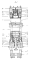
- Fig. 1
- eine Schnittansicht eines Werkzeuggestells, welches als Adaptereinheit in eine nicht dargestellte Presse einsetzbar ist (Schnitt längs Linie I-I von Fig. 3)
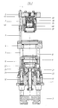
- Fig. 2
- eine Schnittansicht des Werkzeuggestells längs Linie II-II,
- Fig. 3
- einen Schnitt längs der Linie III-III in Fig. 1 sowie
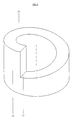
- Fig. 4
- eine rein schematische Darstellung eines Teils eines Einstellrings für einen Topf.
- Fig. 1
- a sectional view of a tool frame which can be used as an adapter unit in a press, not shown (section along line II of Fig. 3)
- Fig. 2
- 2 shows a sectional view of the tool frame along line II-II,
- Fig. 3
- a section along the line III-III in Fig. 1 and
- Fig. 4
- a purely schematic representation of part of an adjusting ring for a pot.
Das anhand der Fig. 1 bis 4 erläuterte Werkzeuggestell umfaßt eine mit 1 bezeichnete Grundplatte, welche nach dem Einbau des mit 2 bezeichneten Werkzeuggestells mit der Presse fest verbunden und abgestützt ist. In dieser Grundplatte 1 ist ein Rahmenwerk verschieblich geführt, welches aus einer unteren Kupplungsplatte 3 und einer Matrizenhalteplatte 4 aufgebaut ist, die über Zugstangen 5 starr miteinander verbunden sind. Das Rahmenwerk ist Teil des Werkzeuggestells 2. Die verschiebliche Führung des Rahmenwerks in der Grundplatte 1 erfolgt über Zugstangen 5, von denen im dargestellten Ausführungsbeispiel vier entsprechend Fig. 3 vorgesehen sind.The tool frame explained with reference to FIGS. 1 to 4 comprises a base plate designated by 1, which is firmly connected and supported with the press after the installation of the tool frame designated by 2. In this
Die untere Kupplungsplatte 3 ist mit dem unteren Pressenbären der Presse gekoppelt bzw. daran angeschlossen. Der Anschluß des Werkzeuggestells am oberen Pressenbären erfolgt über ein mit 6 bezeichnetes oberes Anschlußstück, welches relativ zur Matritzenhalteplatte 4 geführt ist. Hierzu sind im dargestellten Ausführungsbeispiel vier mit dem oberen Anschlußstück 6 feste Führungsstangen 7 vorgesehen, welche in entsprechenden Öffnungen der Matrizenhalteplatte 4 geführt sind. Alternativ hierzu können die Führungsstangen 7 auch fest mit der Matrizenhalteplatte 4 verbunden sein, so daß das obere Anschlußstück 6 gegenüber den Führungsstangen 7 verschieblich ist.The
Zur Herstellung maßhaltiger gestufter Preßlinge aus Eisenpulver, Keramikpulver oder dgl. werden von der Grundplatte 1 aus insgesamt drei Stempelträger 8, 9 und 10 hydraulisch bewegt. Die Stempelträger 8, 9 und 10 dienen zur Aufnahme der eigentlichen Werkzeugstempel. Wesentlich ist hierbei, daß die Stempelträger 8 bis 10 nicht mehr in Art von Stempelträgerplatten gebildet sind, die an den vier Zugstangen 5 geführt sind, sondern in Art von Töpfen, die an ihren zylindrischen Flächen relativ zur Grundplatte 1 geführt sind, wie im einzelnen noch erläutert wird.In order to produce dimensionally stable, compact compacts from iron powder, ceramic powder or the like, a total of three
Die Bewegung des radial innen liegenden zentrischen Topfes 8 erfolgt über einen Kolben 11, der mit einer Ringschulter 12 in einer den Zylinder der Kolben/Zylinder-Einheit darstellenden Kammer 14 in der Grundplatte 1 aufgenommen ist. Der Topf 8 ist am Kolben 11 befestigt, etwas verschraubt und der Kolben 11 ist in von der Grundplatte 1 aufgenommenen Buchsen 15 uns 15' geführt. Der Topf 9 wiederum ist bei 16 an der Innenfläche einer Hülse 17 geführt, die fest auf der Platte 1 angeordnet ist. Auf der zylinderförmigen Außenfläche ist bei 18 der Topf 10 mit seiner zylinderförmigen Innenfläche geführt. Die Führungsflächen können, wie im dargestellten Ausführungsbeispiel, durch Führungsbuchsen aus einem Material mit besonders guten Gleiteigenschaften gebildet sein. Diese Führungsbuchsen bzw. Beschichtungen sind in der Zeichnung dargestellt. Sie können analog der Führungsbuchse 19 des Topfes 10 am Topf selbst oder an der Gegenfläche ausgebildet sein. Die Dichtelemente sind mit 20 bezeichnet.The movement of the radially inner
Die Bewegung des Topfes 9 erfolgt über zwei aus Fig. 2 ersichtliche Kolben/Zylinder-Einheiten 13, die mit einem Ende in der Grundplatte 1 aufgenommen und mit dem anderen Ende an der Unterseite des Topfes 9 angreifen, und zwar insbesondere an radial vorstehenden Augen 21 des Topfes 9, wie am besten aus Fig. 3 hervorgeht. Zur Bewegung des Topfes 9 werden zwei Kolben/Zylinder-Einheiten verwendet, die entsprechend Fig. 2 diametral gegenüberliegend angeordnet sind. Auch für die Bewegung des Topfes 10 werden zwei diametral gegenüberliegende Kolben/Zylinder-Einheiten 13' verwendet, deren Angriffspunkt am Topf in Fig. 3 mit 22 bezeichnet ist. Wie Fig. 3 recht deutlich zeigt, ist der radiale Abstand der Kolben/Zylinder-Einheiten für den Topf 9 und für den Topf 10 relativ zur Achse des Werkzeuggestells gleich.The movement of the
In der Preßendstellung sind sämtlich Töpfe 8 bis 10 auf Festanschlägen gegenüber der Grundplatte 1 abgestützt. Im dargestellten Ausführungsbeispiel sind diese Festanschläge durch Einstellringe 23, 24 und 25 gebildet. Mit diesen Einstellringen läßt sich auch die Preßendstellung verändern, was insbesondere bei einem Werkzeugverschleiß wesentlich ist. Die Töpfe 8 bis 10 liegen mit ihren unteren axialen Stirnseiten auf den oberen Stirnflächen der Einstellringe 23 bis 25 in der Preßendstellung auf. Wie am besten aus der schematischen Darstellung in Fig. 4 hervorgeht, ist die Auflagefläche 26 für den zugeordneten Topf als schraubflächenartige Rampe, und zwar in Art einer eingängigen Schraubfläche ausgebildet, wobei die Gangenden der Schraubfläche (ein Gang) bei 27 durch eine vertikale Verbindungsfläche verbunden sind. Die entsprechende axiale untere Stirnfläche eines jeden Topfes 8 bis 10 ist komplementär zur Schraubfläche 26 ausgebildet. Die Drehung eines Einstellringes, beispielsweise des Einstellringes 23 hat somit zur Folge, daß je nach Drehrichtung der zugeordnete Topf, hier der Topf 8, angehoben oder abgesenkt wird. Dadurch ist die Preßendstellung über den Hub des Topfes veränderbar bzw. einstellbar. Die Drehbewegung des Einstellringes erfolgt im dargestellten Ausführungsbeispiel jeweils über eine nach außen geführte Schraubspindel, wobei aus Fig. 1 die Schraubspindeln 28 und 29 ersichtlich sind, die den Töpfen 8 und 10 zugeordnet sind. Fig. 3 zeigt schematisch die Schraubspindeln 29 und 30, die den Töpfen 10 und 9 zugeordnet sind.In the press end position, all
Die Einstellringe sind hinsichtlich der Ganghöhe der Schraubenfläche 26 so ausgebildet, daß eine Hubverstellung bis zu 20 mm möglich wäre, da jedoch im bevorzugten Ausführungsbeispiel nur eine Verstellhöhe von etwa 5 mm erforderlich ist, mithin ein jeder Einstellring nur über 90° gedreht werden muß, ist eine Begrenzung der Drehbewegung vorgesehen.The adjusting rings are designed with regard to the pitch of the
Wie sich für den Einstellring 23 aus Fig. 1 ergibt, bedient man sich hierzu eines im Einstellring 23 angeordneten Stiftes 31, der in eine Nut 32 auf der Stirnfläche der Grundplatte 1 eingreift, die sich über einen Winkel von 90° erstreckt. Analoge Begrenzungen können für die anderen Einstellringe vorgesehen sein.As can be seen for the setting
Zur Herstellung kompliziert geformter Preßlinge sind auch am oberen Anschlußstück 6 Stempelträger in Form von Töpfen 34 und 35 angeordnet, die hydraulisch vom oberen Anschlußstück 6 bewegt werden. Ein zentrisch angeordneter Stempelträger 33 wird über eine im oberen Anschlußstück 6 aufgenommene Kolben/Zylinder-Einheit 36 betätigt, dessen Kolben in zwei vom Anschlußstück 6 aufgenommenen Buchsen geführt ist, von denen eine mit 43 bezeichnet ist. Der Topf 34 ist mit seiner zylindrischen Innenfläche an der zylindrischen Außenfläche der Buchse 43 geführt und wird von zwei Kolben/Zylinder-Einheiten betätigt, die an radial nach außen vorstehenden Augen analog zum Topf 9 angreifen und im übrigen auch diametral gegenüberliegend angeordnet sind. Diese Kolben/Zylinder-Einheiten gehen aus Fig. 2 hervor. Auch der Topf 35 wird durch zwei aus Fig. 1 ersichtliche Kolben/Zylinder-Einheiten 37 betätigt, die diametral gegenüberliegend angeordnet sind. Zur Führung des Topfes 34 dient eine fest mit dem oberen Anschlußstück 6 verbundene Hülse 38, in welcher auch die Ringkolben 39 der Kolben/Zylinder-Einheit 37 geführt ist. Die Führung des Topfes 35 erfolgt an der Innenfläche eines hülsenartigen Endteils 40, welches fest mit der Hülse 38 verbunden ist. Ähnlich wie bei den gegenüber der Grundplatte 1 bewegbaren Stempelträgern sind die Töpfe 34 und 35 über Einstellringe 41 und 42 verstellbar, wobei hier auf die Beschreibung zu den unteren Töpfen verwiesen werden kann.For the production of complex shaped
Die Betriebsweise der Presse ist die folgende: Zur Füllungwerden die Stempelträger von der Grundplatte 1 bzw. vom oberen Anschlußstück 6 her nach oben bzw. nach unten in Richtung auf die Matrizenhalteplatte 4 gefahren. Nach dem Füllen der hierdurch entstandenen Form mit Pulver aus keramischem Material erfolgt der Pressenhub durch Zusammenfahren des oberen und unteren Pressenbären, wodurch die Töpfe 8 bis 10 und 31 bis 33 in ihre Preßendstellung gelangen, in der sie über Festanschläge, also die Einstellringe, gegenüber der Grundplatte 1 bzw. dem oberen Anschlußstück 6 abgestützt sind. Hierbei ist über die zusammenwirkenden Flächen der Töpfe und Einstellringe eine gute Kraftübertragung gewährleistet.The operation of the press is as follows: For filling, the punch carriers are moved upwards or downwards from the
Claims (14)
Applications Claiming Priority (2)
| Application Number | Priority Date | Filing Date | Title |
|---|---|---|---|
| DE4000423 | 1990-01-09 | ||
| DE4000423A DE4000423C2 (en) | 1990-01-09 | 1990-01-09 | Press for the production of dimensionally stable compacts from powdered material |
Publications (3)
| Publication Number | Publication Date |
|---|---|
| EP0436792A2 true EP0436792A2 (en) | 1991-07-17 |
| EP0436792A3 EP0436792A3 (en) | 1991-09-18 |
| EP0436792B1 EP0436792B1 (en) | 1994-05-25 |
Family
ID=6397774
Family Applications (1)
| Application Number | Title | Priority Date | Filing Date |
|---|---|---|---|
| EP90121145A Expired - Lifetime EP0436792B1 (en) | 1990-01-09 | 1990-11-05 | Press for making dimensionally stable pressed articles from particulate material |
Country Status (4)
| Country | Link |
|---|---|
| EP (1) | EP0436792B1 (en) |
| JP (1) | JP2941070B2 (en) |
| AT (1) | ATE106040T1 (en) |
| DE (1) | DE4000423C2 (en) |
Cited By (9)
| Publication number | Priority date | Publication date | Assignee | Title |
|---|---|---|---|---|
| EP0561159A1 (en) * | 1992-03-17 | 1993-09-22 | KOMAGE GELLNER MASCHINENFABRIK GmbH | Apparatus for pressing articles from a fine granular material |
| US6902698B2 (en) | 2001-07-20 | 2005-06-07 | Dorst Technologies Gmbh & Co. Kg. | Press apparatus for producing dimensionally accurate pressed articles from a powdered material |
| US7229263B2 (en) | 2002-11-22 | 2007-06-12 | Dorst Technologies Gmbh & Co. Kg | Pressing device for manufacturing of shaped compacts from pulverized material |
| CN102744320A (en) * | 2011-04-21 | 2012-10-24 | 中国北车集团大同电力机车有限责任公司 | Stamping die |
| WO2012126462A3 (en) * | 2011-03-24 | 2013-01-03 | Sms Meer Gmbh | Press for producing a moulded part and method for changing a die on a press |
| CN104338852A (en) * | 2013-08-09 | 2015-02-11 | 睿励科学仪器(上海)有限公司 | Die |
| EP3530448A1 (en) * | 2018-02-26 | 2019-08-28 | Osterwalder AG | Pressing device for a powder press and a tool changing system |
| EP3530446A1 (en) * | 2018-02-26 | 2019-08-28 | Osterwalder AG | Powder press with toggle drive and electrical drive |
| EP3530445A1 (en) * | 2018-02-26 | 2019-08-28 | Osterwalder AG | Powder press with toggle drive |
Families Citing this family (4)
| Publication number | Priority date | Publication date | Assignee | Title |
|---|---|---|---|---|
| DE4227640A1 (en) * | 1992-08-18 | 1994-02-24 | Mannesmann Ag | Press for the production of dimensionally stable compacts |
| JP4766031B2 (en) | 2007-10-23 | 2011-09-07 | トヨタ自動車株式会社 | Inverted moving body and control method of inverted moving body |
| JP4798181B2 (en) | 2008-07-29 | 2011-10-19 | トヨタ自動車株式会社 | MOBILE BODY, TRAVEL DEVICE, AND MOBILE BODY CONTROL METHOD |
| JP4702414B2 (en) | 2008-07-29 | 2011-06-15 | トヨタ自動車株式会社 | Coaxial motorcycle and control method of coaxial motorcycle |
Citations (7)
| Publication number | Priority date | Publication date | Assignee | Title |
|---|---|---|---|---|
| US2556951A (en) * | 1944-06-05 | 1951-06-12 | Stokes Machine Co | Powdered material compacting press |
| GB677234A (en) * | 1947-10-20 | 1952-08-13 | Haller John | An improved machine for briquetting powdered metal |
| US3353215A (en) * | 1965-11-10 | 1967-11-21 | Haller John | Powdered material briquetting press |
| FR2052127A5 (en) * | 1969-07-18 | 1971-04-09 | Basset Jacques | |
| DE2237097A1 (en) * | 1971-08-10 | 1973-03-01 | Olivetti & Co Spa | PROCESS AND PRESS FOR COMPRESSING MATERIALS IN POWDER FORM FOR WORKPIECES TO BE SINTERED |
| DE3142126A1 (en) * | 1981-10-23 | 1983-05-11 | Dorst-Keramikmaschinen-Bau Otto Dorst U. Dipl.-Ing. Walter Schlegel, 8113 Kochel | "PRESS FOR THE PRODUCTION OF TAILORED PRESSINGS FROM POWDER-SHAPED MATERIAL" |
| JPS62199298A (en) * | 1986-02-28 | 1987-09-02 | Mazda Motor Corp | Powder press device |
Family Cites Families (2)
| Publication number | Priority date | Publication date | Assignee | Title |
|---|---|---|---|---|
| US2810929A (en) * | 1953-05-06 | 1957-10-29 | Baldwin Lima Hamilton Corp | Apparatus for compacting and ejecting flanged articles |
| US3593366A (en) * | 1968-12-11 | 1971-07-20 | Wolverine Pentronix | Multiple punch tool set for powder compacting press |
-
1990
- 1990-01-09 DE DE4000423A patent/DE4000423C2/en not_active Expired - Lifetime
- 1990-11-05 EP EP90121145A patent/EP0436792B1/en not_active Expired - Lifetime
- 1990-11-05 AT AT90121145T patent/ATE106040T1/en not_active IP Right Cessation
-
1991
- 1991-01-08 JP JP3000428A patent/JP2941070B2/en not_active Expired - Fee Related
Patent Citations (7)
| Publication number | Priority date | Publication date | Assignee | Title |
|---|---|---|---|---|
| US2556951A (en) * | 1944-06-05 | 1951-06-12 | Stokes Machine Co | Powdered material compacting press |
| GB677234A (en) * | 1947-10-20 | 1952-08-13 | Haller John | An improved machine for briquetting powdered metal |
| US3353215A (en) * | 1965-11-10 | 1967-11-21 | Haller John | Powdered material briquetting press |
| FR2052127A5 (en) * | 1969-07-18 | 1971-04-09 | Basset Jacques | |
| DE2237097A1 (en) * | 1971-08-10 | 1973-03-01 | Olivetti & Co Spa | PROCESS AND PRESS FOR COMPRESSING MATERIALS IN POWDER FORM FOR WORKPIECES TO BE SINTERED |
| DE3142126A1 (en) * | 1981-10-23 | 1983-05-11 | Dorst-Keramikmaschinen-Bau Otto Dorst U. Dipl.-Ing. Walter Schlegel, 8113 Kochel | "PRESS FOR THE PRODUCTION OF TAILORED PRESSINGS FROM POWDER-SHAPED MATERIAL" |
| JPS62199298A (en) * | 1986-02-28 | 1987-09-02 | Mazda Motor Corp | Powder press device |
Non-Patent Citations (1)
| Title |
|---|
| PATENT ABSTRACTS OF JAPAN vol. 12, no. 52 (M-668)(2899) 17. Februar 1988 & JP-A-62 199 298 (MAZDA MOTOR CORP. ) 2. September 1987 * |
Cited By (18)
| Publication number | Priority date | Publication date | Assignee | Title |
|---|---|---|---|---|
| EP0561159A1 (en) * | 1992-03-17 | 1993-09-22 | KOMAGE GELLNER MASCHINENFABRIK GmbH | Apparatus for pressing articles from a fine granular material |
| US6902698B2 (en) | 2001-07-20 | 2005-06-07 | Dorst Technologies Gmbh & Co. Kg. | Press apparatus for producing dimensionally accurate pressed articles from a powdered material |
| US7229263B2 (en) | 2002-11-22 | 2007-06-12 | Dorst Technologies Gmbh & Co. Kg | Pressing device for manufacturing of shaped compacts from pulverized material |
| US9724846B2 (en) | 2011-03-24 | 2017-08-08 | Sms Group Gmbh | Press for producing a molded part and method for changing a die on a press |
| WO2012126462A3 (en) * | 2011-03-24 | 2013-01-03 | Sms Meer Gmbh | Press for producing a moulded part and method for changing a die on a press |
| US10647027B2 (en) | 2011-03-24 | 2020-05-12 | Sms Group Gmbh | Press for production of a molded part and method for changing a die on a press |
| CN102744320B (en) * | 2011-04-21 | 2014-11-19 | 中国北车集团大同电力机车有限责任公司 | Stamping die |
| CN102744320A (en) * | 2011-04-21 | 2012-10-24 | 中国北车集团大同电力机车有限责任公司 | Stamping die |
| CN104338852A (en) * | 2013-08-09 | 2015-02-11 | 睿励科学仪器(上海)有限公司 | Die |
| CN104338852B (en) * | 2013-08-09 | 2016-05-25 | 睿励科学仪器(上海)有限公司 | A kind of mould |
| EP3530446A1 (en) * | 2018-02-26 | 2019-08-28 | Osterwalder AG | Powder press with toggle drive and electrical drive |
| EP3530445A1 (en) * | 2018-02-26 | 2019-08-28 | Osterwalder AG | Powder press with toggle drive |
| WO2019162511A1 (en) * | 2018-02-26 | 2019-08-29 | Osterwalder Ag | Powder press having toggle lever drive and electric drive |
| WO2019162510A1 (en) * | 2018-02-26 | 2019-08-29 | Osterwalder Ag | Press device for a powder press and a tool changing system |
| EP3530448A1 (en) * | 2018-02-26 | 2019-08-28 | Osterwalder AG | Pressing device for a powder press and a tool changing system |
| CN111770831A (en) * | 2018-02-26 | 2020-10-13 | 奥斯瓦尔德股份公司 | Powder press with toggle lever drive and electric drive |
| CN111819072A (en) * | 2018-02-26 | 2020-10-23 | 奥斯瓦尔德股份公司 | Pressing device for powder press and tool changing system |
| US11820094B2 (en) | 2018-02-26 | 2023-11-21 | Osterwalder Ag | Powder press having toggle lever drive and electric drive |
Also Published As
| Publication number | Publication date |
|---|---|
| EP0436792B1 (en) | 1994-05-25 |
| EP0436792A3 (en) | 1991-09-18 |
| JPH04162995A (en) | 1992-06-08 |
| DE4000423A1 (en) | 1991-07-11 |
| DE4000423C2 (en) | 1998-10-08 |
| JP2941070B2 (en) | 1999-08-25 |
| ATE106040T1 (en) | 1994-06-15 |
Similar Documents
| Publication | Publication Date | Title |
|---|---|---|
| DE3110221C2 (en) | Turret punch press | |
| EP0108935B1 (en) | Stamping machine having a multiple punch | |
| EP0436792B1 (en) | Press for making dimensionally stable pressed articles from particulate material | |
| DE2801225A1 (en) | PRESSING TOOL FOR PRESSING A POWDER-FORMED MATERIAL INTO A SHAPED WORKPIECE | |
| DE10140270A1 (en) | Press tongs for pressing notches into contact element has adjustable stop for press stamps and hence press depth, lock with single fixed trigger point, force-displacement compensator | |
| EP1764173B1 (en) | Powder moulding press | |
| EP1422050B1 (en) | Pressing apparatus for manufacturing dimensionally stable pressed articles from powdery materials | |
| DE4136506A1 (en) | KNIFE HOLDER FOR LONG CUTTING STATIONS ON PAPER PROCESSING MACHINES | |
| EP2036710B1 (en) | Rotor for a rotary tablet compactor | |
| EP2387542B1 (en) | Closure head for container closure machines and container closure machine | |
| DE1948119B2 (en) | PARTIAL EQUIPMENT ON A MACHINE FOR BEVELING FACE EDGES ON BEVEL PINIONS | |
| DE2437753B2 (en) | Stroke-adjustable, double-acting piston motor | |
| DE3342948C2 (en) | ||
| EP1731246A1 (en) | Apparatus to produce a variety of formed parts of powder. | |
| DE4022871C2 (en) | ||
| DE102020121142B4 (en) | radial press | |
| DE3432939C2 (en) | ||
| DE10158861A1 (en) | Device to move press ram has spindle and spindle nut with outer side formed as double piston rod and guided in cylinder via ring piston | |
| DE19649063A1 (en) | Blanking or forming press | |
| EP4279257A1 (en) | Tabletting tool | |
| DE4032106A1 (en) | Hydraulic press with fine adjustment of platen locking collar | |
| AT379986B (en) | MECHANICAL PRESS WITH UNDER-TABLE DRIVE | |
| DE10063560C2 (en) | Tool height adjustment device on punch presses and punch press | |
| DE2644680C3 (en) | Device on a press for the deformation of cylindrical blanks | |
| DE4401506C1 (en) | Mounting of a drum in a press for ceramic compositions, in particular for the production of roofing tiles |
Legal Events
| Date | Code | Title | Description |
|---|---|---|---|
| PUAI | Public reference made under article 153(3) epc to a published international application that has entered the european phase |
Free format text: ORIGINAL CODE: 0009012 |
|
| AK | Designated contracting states |
Kind code of ref document: A2 Designated state(s): AT CH FR GB IT LI SE |
|
| PUAL | Search report despatched |
Free format text: ORIGINAL CODE: 0009013 |
|
| AK | Designated contracting states |
Kind code of ref document: A3 Designated state(s): AT CH FR GB IT LI SE |
|
| 17P | Request for examination filed |
Effective date: 19920318 |
|
| 17Q | First examination report despatched |
Effective date: 19930630 |
|
| GRAA | (expected) grant |
Free format text: ORIGINAL CODE: 0009210 |
|
| AK | Designated contracting states |
Kind code of ref document: B1 Designated state(s): AT CH FR GB IT LI SE |
|
| PG25 | Lapsed in a contracting state [announced via postgrant information from national office to epo] |
Ref country code: SE Free format text: THE PATENT HAS BEEN ANNULLED BY A DECISION OF A NATIONAL AUTHORITY Effective date: 19940525 |
|
| REF | Corresponds to: |
Ref document number: 106040 Country of ref document: AT Date of ref document: 19940615 Kind code of ref document: T |
|
| GBT | Gb: translation of ep patent filed (gb section 77(6)(a)/1977) |
Effective date: 19940606 |
|
| ET | Fr: translation filed | ||
| ITF | It: translation for a ep patent filed |
Owner name: PROPRIA PROT. PROPRIETA' IND. |
|
| PG25 | Lapsed in a contracting state [announced via postgrant information from national office to epo] |
Ref country code: AT Effective date: 19941105 |
|
| PLBE | No opposition filed within time limit |
Free format text: ORIGINAL CODE: 0009261 |
|
| STAA | Information on the status of an ep patent application or granted ep patent |
Free format text: STATUS: NO OPPOSITION FILED WITHIN TIME LIMIT |
|
| 26N | No opposition filed | ||
| REG | Reference to a national code |
Ref country code: GB Ref legal event code: IF02 |
|
| REG | Reference to a national code |
Ref country code: CH Ref legal event code: PFA Owner name: DORST TECHNOLOGIES GMBH & CO. KG Free format text: DORST MASCHINEN UND ANLAGENBAU OTTO DORST UND DIPL.-ING. WALTER SCHLEGEL GMBH & CO.#MITTENWALDERSTRASSE 61 P.O. BOX 109 + 129#KOCHEL AM SEE (DE) -TRANSFER TO- DORST TECHNOLOGIES GMBH & CO. KG#MITTENWALDERSTRASSE 61 P.O. BOX 109 + 129#KOCHEL AM SEE (DE) Ref country code: CH Ref legal event code: NV Representative=s name: TROESCH SCHEIDEGGER WERNER AG Ref country code: GB Ref legal event code: 732E |
|
| REG | Reference to a national code |
Ref country code: FR Ref legal event code: CD |
|
| PGFP | Annual fee paid to national office [announced via postgrant information from national office to epo] |
Ref country code: GB Payment date: 20071123 Year of fee payment: 18 |
|
| PGFP | Annual fee paid to national office [announced via postgrant information from national office to epo] |
Ref country code: FR Payment date: 20081118 Year of fee payment: 19 |
|
| GBPC | Gb: european patent ceased through non-payment of renewal fee |
Effective date: 20081105 |
|
| PG25 | Lapsed in a contracting state [announced via postgrant information from national office to epo] |
Ref country code: GB Free format text: LAPSE BECAUSE OF NON-PAYMENT OF DUE FEES Effective date: 20081105 |
|
| PGFP | Annual fee paid to national office [announced via postgrant information from national office to epo] |
Ref country code: CH Payment date: 20091124 Year of fee payment: 20 |
|
| PGFP | Annual fee paid to national office [announced via postgrant information from national office to epo] |
Ref country code: IT Payment date: 20091128 Year of fee payment: 20 |
|
| REG | Reference to a national code |
Ref country code: FR Ref legal event code: ST Effective date: 20100730 |
|
| PG25 | Lapsed in a contracting state [announced via postgrant information from national office to epo] |
Ref country code: FR Free format text: LAPSE BECAUSE OF NON-PAYMENT OF DUE FEES Effective date: 20091130 |
|
| REG | Reference to a national code |
Ref country code: CH Ref legal event code: PL |