EP0436569B1 - A single tier dryer section and a method of drying a web - Google Patents
A single tier dryer section and a method of drying a web Download PDFInfo
- Publication number
- EP0436569B1 EP0436569B1 EP89909486A EP89909486A EP0436569B1 EP 0436569 B1 EP0436569 B1 EP 0436569B1 EP 89909486 A EP89909486 A EP 89909486A EP 89909486 A EP89909486 A EP 89909486A EP 0436569 B1 EP0436569 B1 EP 0436569B1
- Authority
- EP
- European Patent Office
- Prior art keywords
- web
- dryer
- felt
- roll
- disposed
- Prior art date
- Legal status (The legal status is an assumption and is not a legal conclusion. Google has not performed a legal analysis and makes no representation as to the accuracy of the status listed.)
- Expired - Lifetime
Links
- 238000001035 drying Methods 0.000 title claims abstract description 23
- 238000000034 method Methods 0.000 title claims description 8
- 238000005520 cutting process Methods 0.000 claims abstract description 18
- 238000011144 upstream manufacturing Methods 0.000 claims abstract description 13
- 239000012530 fluid Substances 0.000 claims description 10
- 238000004891 communication Methods 0.000 claims description 6
- 238000007664 blowing Methods 0.000 claims description 3
- 238000009434 installation Methods 0.000 description 2
- 235000010627 Phaseolus vulgaris Nutrition 0.000 description 1
- 244000046052 Phaseolus vulgaris Species 0.000 description 1
- 238000010276 construction Methods 0.000 description 1
- 230000000087 stabilizing effect Effects 0.000 description 1
- 238000009423 ventilation Methods 0.000 description 1
Images

Classifications
-
- D—TEXTILES; PAPER
- D21—PAPER-MAKING; PRODUCTION OF CELLULOSE
- D21F—PAPER-MAKING MACHINES; METHODS OF PRODUCING PAPER THEREON
- D21F5/00—Dryer section of machines for making continuous webs of paper
- D21F5/02—Drying on cylinders
- D21F5/04—Drying on cylinders on two or more drying cylinders
-
- D—TEXTILES; PAPER
- D21—PAPER-MAKING; PRODUCTION OF CELLULOSE
- D21F—PAPER-MAKING MACHINES; METHODS OF PRODUCING PAPER THEREON
- D21F5/00—Dryer section of machines for making continuous webs of paper
- D21F5/02—Drying on cylinders
- D21F5/04—Drying on cylinders on two or more drying cylinders
- D21F5/042—Drying on cylinders on two or more drying cylinders in combination with suction or blowing devices
-
- D—TEXTILES; PAPER
- D21—PAPER-MAKING; PRODUCTION OF CELLULOSE
- D21G—CALENDERS; ACCESSORIES FOR PAPER-MAKING MACHINES
- D21G9/00—Other accessories for paper-making machines
- D21G9/0063—Devices for threading a web tail through a paper-making machine
Definitions
- This invention relates to a single tier dryer section as defined in the preamble of claim 1.
- the invention also relates to a method of drying a web as defined in the preamble of claim 22.
- WO-A-88 04206 discloses such a single tier dryer section and such a method. Groups of single tier dryers extend from the press section to the calender in such a single tier dryer section.
- Total BelRun The aforementioned dryer concept, which is known as Total BelRun concept, enables alternate sides of the web to be sequentially dried during passage of the web through successive dryer sections. Additionally, the Total BelRun dryer concept maintains a positive sheet shrinkage restraint in a cross-machine direction as a high vacuum level is applied to each transfer vacuum roll disposed between adjacent dryers.
- Total BelRun is a Registered Trademark of Beloit Corporation.
- the aforementioned Total BelRun system offers several advantages over conventional drying arrangements. First, long open draws between consecutive dryers within a dryer section are eliminated thereby improving the runnability of the web. Second, the vacuum rolls between dryers maintain a sheet shrinkage restraint in the cross-machine direction resulting in more uniform sheet properties.
- US-A-1,402,451 shows a tail cutter disposed in an open draw defined between an upper dryer and a lower dryer of a two-tier dryer section having a single felt which is guided only around the upper dryers.
- the present invention provides a solution to the aforementioned problem by providing a short open draw between two adjacent dryers in the last dryer section of a Total BelRun dryer section and the installation of a tail cutter in such open draw.
- the Total BelRun drying restraint can be extended through the last dryer section where the last portion of the sheet shrinkage normally takes place.
- the paper has nearly developed its full strength during passage through the last dryer section and the web can withstand the stresses induced during the cutting operation without having to pass through several preceding open draws.
- the length of the aforementioned open draw can be made very short by the provision of the present invention.
- the draw length is often dictated by the specific dryer geometry which is required for runnability, roll and doctor mounting and for ventilation whereas in the dryer arrangement of the present invention, the open draw can be made merely of sufficient length to accommodate the tail cutter.
- the broke will fall directly into the basement according to the provisions of the present invention.
- the tail can be threaded according to the present invention through such open draw by the use of special air nozzles without the use of threading ropes.
- the aforementioned object is achieved by implementing the features of the characterising portion of claim 1 in a single tier dryer section as defined in the preamble of claim 1.
- the dryer and the further dryer are consecutive and the further dryer is the last dryer in the drying section.
- the dryer and the further dryer are top felted and the felt roll has a cylindrical external surface which defines a plurality of spiral circumferential grooves therein.
- the felt roll is a plain roll and in a further embodiment of the present invention, the felt roll is a vacuum roll.
- the guide roll is a vacuum roll and includes a perforate shell and a stationary duct disposed within and along the length of the shell.
- the duct and shell define therebetween a chamber with the duct being in fluid communication with the chamber.
- the duct is connected to a source of partial vacuum for urging the web into close conformity with the shell.
- Seal means extend from the shell to the duct for dividing the chamber into a first and a second cavity and the first cavity is in fluid communication with the duct so that the partial vacuum is concentrated in the vicinity of the web where the web wraps around the shell.
- the guide roll has a cylindrical outer surface which defines a plurality of spiral circumferential grooves therein.
- the tail cutter means includes a rotary saw which is movable from an inoperative position to an operative position thereof for cutting the tail of the web.
- the tail cutter means is movable from an inoperative to an operative position thereof and the cutter means includes a nozzle means for ejecting high pressure fluid towards the web for cutting the tail therefrom when the cutter means is disposed in the operative position.
- the cutter means also includes a guide plate disposed parallel to and closely adjacent to the web which extends through the open draw when the cutter means is disposed in the operative position.
- an air jet means is disposed between the plate and the web for generating an air cushion between the plate and the web when the cutter means is disposed in the operative position thereof adjacent to the web.
- the tail cutter means is movable in a cross-machine direction for widening the tail to the full width of the web.
- the tail cutter means includes a blade and a guide plate for supporting the blade.
- the plate is disposed parallel to the web when the tail cutter means is in an operative position thereof.
- the tail cutter apparatus also includes threading means for threading an initial tail of the web through the open draws.
- the threading means includes an air nozzle which is disposed upstream relative to the guide roll and downstream relative to the felt roll for blowing the initial tail away from the felt roll so that the initial tail of the web is led from the felt roll towards the guide roll.
- the threading means includes a plurality of air chutes which are disposed adjacent to the guide roll for guiding the initial tail of the web extending around the guide roll towards the felt roll.
- the threading means includes a looped belt conveyor which is disposed closely adjacent to the guide roll for directing the initial tail of the web around the guide roll.
- the threading means includes a combination of the aforementioned air nozzle, looped belt conveyor and air chute.
- the belt conveyor is replaced by a bottom felt.
- the threading means includes a looped belt conveyor having a belt which is movable from an inoperative to an operative threading position.
- the belt when disposed in the threading position, extends contiguously around a portion of the outer surface of the guide roll for defining an ingoing and an outgoing nip respectively between the belt and the guide roll.
- An initial tail of the web is guided into the ingoing nip such that the initial tail is disposed between the guide roll and the belt.
- An ingoing and an outgoing movable roll are disposed respectively upstream and downstream relative to the guide roll such that the belt is looped around these movable rolls.
- the movable rolls are movable from an operative threading position wherein the movable rolls are disposed adjacent to the felt roll to an inoperative position away from the felt roll.
- the tail cutter apparatus includes an elongate double concave edge blow box which is disposed between the felt roll and the guide roll.
- the blow box is connected to a source of pressurized air and the box defines a first and a second planar surface disposed respectively parallel to the first and second open draws.
- the planar surfaces define a plurality of orifices such that an air cushion is generated between the blow box and the initial tail extending through the open draws.
- the planar surface which is disposed adjacent to the tail cutter means, defines an axial slot for the reception therein of the tail cutter means.
- the preferred embodiment of the present invention also includes a box means which is disposed between the dryer and the felt roll for urging the web into close conformity with the felt.
- box means is connected to a source of pressurized air and defines an opening for directing a current of air for urging the web towards the felt.
- the aforementioned object is achieved by incorporating the steps defined in the characterising portion of claim 22 into the method defined in the preamble of claim 22.
- Figure 1 is an elevational view of a last group of dryers generally designed 10 of a prior art double felted dryer section.
- the group 10 includes upper dryers 12, 13, 14 and 15 and lower dryers 16, 17 and 18 forming an upper and a lower tier 20 and 22 respectively.
- An upper and a lower felt 24 and 26 extend respectively around the dryers of the upper and lower tier 20 and 22.
- a web W extends in sinusoidal configuration alternately between dryers of the upper and lower tier with the web extending in open draw 28 between successive dryers 18 and 15.
- a tail cutter 30 is disposed adjacent to the open draw 28 for cutting a tail from the web W prior to the web extending around the last dryer 15 onto a calender or size press or the like.
- the present invention overcomes the aforementioned problems by the provision of a single tier group generally designated 10A shown in figure 2 for guiding and drying a web WA immediately upstream relative to a calender or the like.
- a tail cutter apparatus generally designated 32 for cutting a tail from a web WA extending through a single tier dryer section includes a dryer 14A of the drying section and a felt F which extends contiguously with the web WA around the dryer 14A.
- the web WA is disposed between the felt F and the dryer 14A for drying the web WA.
- a further dryer 15A is disposed downstream relative to the dryer 14A.
- the felt F and the web WA extend contiguously around the further dryer 15A with the web WA being disposed between the felt F and the further dryer 15A for further drying the web WA.
- a felt roll 34 is disposed downstream relative to the dryer 14A and upstream relative to the further dryer 15A for guiding the felt F during movement of the felt F between the dryer 14A and the further dryer 15A.
- a guide roll generally designated 36 is disposed downstream relative to the dryer 14A and upstream relative to the further dryer 15A for guiding the web WA during movement of the web WA away from and towards the felt roll 34 such that a first and second open draw 28A and 38 respectively of the web WA are defined between the felt roll 34 and the guide roll 36.
- a tail cutter means generally designated 30A is disposed adjacent to one of the open draws 28A or 38 for cutting the tail from the web WA.
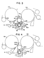
- Figure 3 is an enlarged elevational view of the dryer 14A and the further dryer 15A showing the location of the felt roll 34 and the guide roll 36. As shown in figure 3, the dryer 14A and the further dryer 15A are consecutive with the further dryer 15A being the last dryer in the drying section.
- the dryers 14A and 15A are top felted and the felt roll 34 has a cylindrical external surface 40 which defines a plurality of spiral circumferential grooves therein diagramatically represented by 42.
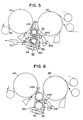
- the felt roll 34B is a plain roll.
- the felt roll 34C is a vacuum roll.
- the guide roll 36C is a vacuum roll and includes a perforate shell 44 and a stationary duct 46 which is disposed within and along the length of the shell 44.
- the duct 46 and the shell 44 define therebetween a chamber generally designated 48.
- the duct 46 is in fluid communication with the chamber 48 and is connected to a source of partial vacuum 50 such that the web WC is urged into close conformity with the shell 44.
- Seal means 52 extend from the shell 44 to the duct 46 for dividing the chamber 48 into a first and a second cavity 54 and 56 respectively.
- the first cavity 54 is in fluid communication via hole 58 with the duct 46 so that the partial vacuum is concentrated in the vicinity of the web WC where the web WC wraps around the shell 44.
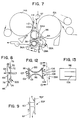
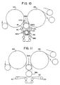
- Figure 6 is an elevational view of another embodiment of the present invention in which the guide roll 36D has a cylindrical outer surface 60 which defines a plurality of spiral circumferential grooves therein diagramatically represented by 62.
- the tail cutter means 30A, 30B, 30C and 30D include a rotary saw 64, 64B, 64C and 64D respectively which are movable from an inoperative position shown in figure 7 to an operative position shown in figure 3 for cutting the tail from the web.
- Figure 8 is an enlarged elevational view of an alternative embodiment of the present invention in which a tail cutter means generally designated 30E is movable from an inoperative to an operative position thereof.
- the cutter means 30E including a nozzle means 66 for ejecting high pressure fluid as represented by the arrow 68 towards the web WE for cutting the tail therefrom when the cutter means 30E is disposed in the operative position as shown in figure 8.
- a guide plate 70 is disposed parallel to and closely adjacent to the web WE extending through the open draw when the cutter means 30E is disposed in the operative position.
- an air jet means 72 and 74 is disposed between the plate 70 and the web WE for generating an air cushion as represented by the arrows 76 and 78 between the plate 70 and the web WE when the cutter means 30E is disposed in the operative position thereof as shown in figure 8 adjacent to the web WE.
- the tail cutter means 30E is movable in a cross-machine direction for widening the tail to the full width of the web.
- Figure 9 is an enlarged elevational view of an alternative tail cutter means 30F which includes a blade 80 and a guide plate 70F for supporting the blade 80.
- the plate 70F is disposed parallel to the web WF when the tail cutter means 30F is in an operative position thereof.
- a threading means generally designated 82 includes an air nozzle 84 disposed upstream relative to the guide roll 36 and downstream relative to the felt roll 34 for blowing the initial tail away from the dryer 14A so that the initial tail of the web WA is led from the dryer 14A towards the guide roll 36.
- Figure 3 also shows the threading means 82 as including a plurality of air chutes 86 disposed adjacent to the guide roll 36 for directing the initial tail of the web WA extending around the guide rail 36 towards the felt roll 34.
- the threading means 82 also includes a looped belt conveyor 88 disposed closely adjacent to the guide roll 36 for directing the initial tail of the web around the guide roll 36.
- the tail cutter apparatus can include an air nozzle 84, a looped belt conveyor 88 and an air chute 86 for assisting threading of an initial tail of the web around the guide roll 36.
- the threading means 82G includes a belt 90 movable from an inoperative to an operative threading position as shown in figure 10.
- the belt 90 when disposed in the threading position as shown in figure 10, extends contiguously around a portion of the outer surface 60G of the guide roll 36G for defining an ingoing and an outgoing nip IN and ON respectively between the belt 90 and the guide roll 36G.
- the initial tail is guided into the ingoing nip IN such that the initial tail is disposed between the guide roll 36G and the belt 90.
- An ingoing and an outgoing movable roll 92 and 94 respectively are disposed upstream and downstream relative to the guide roll 36G such that the belt 90 is looped around the movable rolls 92 and 94 respectively.
- the movable rolls 92 and 94 are movable from an operative threading position shown in figure 10 with the movable rolls 92 and 94 disposed adjacent to the felt roll 34G to an inoperative position as shown in figure 11 with the movable rolls 92 and 94 disposed away from the felt roll 34G.
- Figure 12 is an enlarged sectional view of an elongate double concave edge blow box 96 shown in figure 7 which is disposed between the felt roll 34A and the guide roll 36A.
- the blow box 96 is connected to a source of pressurized air 97.
- the box 96 defines a first and a second planar surface 98 and 99 respectively which are disposed parallel to the first and second open draws 28A and 38 respectively.
- the planar surfaces 98 and 99 define a plurality of orifices 100, 101, 102, 103 and 104 such that an air cushion as represented by the arrows 106, 107 is generated between the blow box and an initial tail extending through the open draws 38 and 28A.
- Figure 13 is a view taken on the line 13-13 of figure 12 and shows the planar surface 98 disposed adjacent to the tail cutter means 30A.
- This planar surface 98 defines an axial slot 108 for the reception therein of the tail cutter means 30A.
- Figures 3 to 7 show the inclusion of box means 110, 110B, 110C and 110D disposed between the dryer and the felt roll for urging the web into close conformity with the felt.
- the box means is connected to a source of pressurized air 97 shown in figure 7 and defines an opening 112 for directing a current of air shown by the arrow 114 far urging the web towards the felt.
- the web is led contiguously from the dryer 14A to the felt roll 34, the web WA being blown from the dryer 14A by air nozzle 84.
- the felt F follows the felt roll 34 and the web is guided in open draw 38 around guide roll 36.
- Belt conveyor 88 and air chute 86 assist in guiding an initial tail of the web around the guide roll 36 and upwardly towards the felt roll 34 where the initial tail and supporting felt extend contiguously around the further dryer 15A.
- the initial tail When the initial tail has bean threaded around the further dryer 15A, the initial tail is widened to a full width web so that the full width web extends around dryer 14A, guide roll 36 and thereafter around the further dryer 15A.
- a tail cutter 30A is movable from an inoperative to an operative position shown in figure 3 for cutting a tail from the web WA as the web WA extends through the open draw 28A.
- the operation of the embodiments shown in figures 4 and 5 are similar to the operation of the embodiment shown in figures 2 and 3 except in that in the embodiment of figure 4, the felt roll is a plain roll and in figure 5 the felt roll 34C is a vacuum roll and is connected to the source of partial vacuum 50.
- a grooved guide roll is used for guiding the web in order to generate open draws of the web between the felt roll and the guide roll.
- FIG 8 The embodiment shown in figure 8 is similar to that shown in the other embodiments except in that a nozzle means 66 is used for cutting a tail from a web.
- Figure 9 includes a stationary blade 80 which when in the operative position shown in figure 9 cuts a tail from the web WF.
- Figures 10 and 11 show the operation of an initial tail threader wherein the initial tail is directed towards an ingoing nip IN so that the initial tail is guided by the belt 90 around the guide roll 36. Thereafter the initial tail is guided out of the outgoing nip towards the felt roll 34G.
- the belt 90 is no longer in contact with the web as the web extends around the guide roll 36G.
- the slot 108 is provided for the reception of the tail cutter so that the tail cutter in the operative position thereof does not foul the edge box 96.
- the present invention provides a tail cutter apparatus that is of relatively simply construction while maintaining all of the advantages of cross-machine directional sheet restraint from the press to a calendar.
- the tail cutter apparatus also introduces open draws of minimal length.
Landscapes
- Paper (AREA)
- Excavating Of Shafts Or Tunnels (AREA)
- Shearing Machines (AREA)
- Treatment Of Fiber Materials (AREA)
Applications Claiming Priority (3)
| Application Number | Priority Date | Filing Date | Title |
|---|---|---|---|
| US07/235,394 US4918836A (en) | 1987-02-13 | 1988-08-23 | Tail cutter apparatus and method |
| PCT/US1989/003498 WO1990002225A1 (en) | 1988-08-23 | 1989-08-14 | A tail cutter apparatus and method |
| US235394 | 1994-04-29 |
Publications (2)
| Publication Number | Publication Date |
|---|---|
| EP0436569A1 EP0436569A1 (en) | 1991-07-17 |
| EP0436569B1 true EP0436569B1 (en) | 1995-11-22 |
Family
ID=22885313
Family Applications (1)
| Application Number | Title | Priority Date | Filing Date |
|---|---|---|---|
| EP89909486A Expired - Lifetime EP0436569B1 (en) | 1988-08-23 | 1989-08-14 | A single tier dryer section and a method of drying a web |
Country Status (10)
| Country | Link |
|---|---|
| US (1) | US4918836A (fi) |
| EP (1) | EP0436569B1 (fi) |
| JP (1) | JPH0768676B2 (fi) |
| KR (1) | KR940001531B1 (fi) |
| AU (1) | AU633268B2 (fi) |
| BR (1) | BR8907613A (fi) |
| CA (1) | CA1324752C (fi) |
| DE (1) | DE68924917T2 (fi) |
| FI (1) | FI92082C (fi) |
| WO (1) | WO1990002225A1 (fi) |
Families Citing this family (26)
| Publication number | Priority date | Publication date | Assignee | Title |
|---|---|---|---|---|
| US5404653A (en) * | 1987-02-13 | 1995-04-11 | Beloit Technologies, Inc. | Apparatus for drying a web |
| US6049999A (en) * | 1987-02-13 | 2000-04-18 | Beloit Technologies, Inc. | Machine and process for the restrained drying of a paper web |
| US5507104A (en) * | 1987-02-13 | 1996-04-16 | Beloit Technologies, Inc. | Web drying apparatus |
| FI84742C (fi) * | 1990-02-22 | 1992-01-10 | Valmet Paper Machinery Inc | Foerfarande och anordning vid skaerning av spetsdragningsbandet av en pappersbana. |
| DE4012246C1 (fi) * | 1990-04-14 | 1991-06-27 | J.M. Voith Gmbh, 7920 Heidenheim, De | |
| DE4015942C1 (fi) * | 1990-05-18 | 1991-06-06 | J.M. Voith Gmbh, 7920 Heidenheim, De | |
| US5072527A (en) * | 1990-06-06 | 1991-12-17 | Loomie Leo S | Method and apparatus for conveying and tensioning a length of sheet material |
| FI86900C (fi) * | 1990-10-01 | 1992-10-26 | Valmet Paper Machinery Inc | Foerfarande och anordning vid spetsdragning av en pappersbana i maongcylindertorken av en pappersmaskin |
| DE4038250C1 (fi) * | 1990-11-30 | 1992-01-30 | J.M. Voith Gmbh, 7920 Heidenheim, De | |
| US5087325A (en) * | 1991-03-13 | 1992-02-11 | Beloit Corporation | Apparatus for manufacturing a dried web of paper |
| US5762284A (en) * | 1993-02-19 | 1998-06-09 | Valmet Corporation | Assembly for the unwinder end of an off-machine paper web handling line |
| US5337490A (en) * | 1993-06-21 | 1994-08-16 | Champion International Corporation | Single tier dryer threading nozzle for paper machines |
| US5600897A (en) * | 1993-08-06 | 1997-02-11 | J.M. Voith Gmbh | Mixed dryer section including single-tier and double-tier drying groups with automatic ropeless threading |
| FI98229C (fi) * | 1993-08-23 | 1997-05-12 | Valmet Paper Machinery Inc | Paperikoneen kuivatusosa |
| US5505006A (en) * | 1994-09-08 | 1996-04-09 | J.M. Voith Gmbh | Device for drying a running web |
| DE29510637U1 (de) * | 1995-06-30 | 1995-10-19 | Voith Sulzer Papiermaschinen GmbH, 89522 Heidenheim | Ein-Filz-Trockengruppe |
| US5767481A (en) * | 1995-09-18 | 1998-06-16 | Voith Sulzer Paper Technology North America, Inc. | Laser tail cutter assembly |
| DE19602492C2 (de) * | 1996-01-25 | 2000-12-07 | Voith Sulzer Papiermasch Gmbh | Maschine zur Herstellung einer Papier- oder Kartonbahn |
| EP0802278A3 (de) * | 1996-04-19 | 1998-07-01 | Voith Sulzer Papiermaschinen GmbH | Ein-Filz-Trockengruppe |
| CA2208381A1 (en) * | 1997-06-20 | 1998-12-20 | Roman C. Caspar | Apparatus for cutting and threading a tail of a travelling web in a papermaking machine |
| FI104840B (fi) * | 1999-02-18 | 2000-04-14 | Valmet Corp | Päänvientinauhan katkaisulaite |
| FI108057B (fi) * | 2000-09-06 | 2001-11-15 | Metso Paper Inc | Järjestely paperi-/kartonki- tai jälkikäsittelykoneen monitelakalanterin ratavienniksi |
| AT413709B (de) * | 2004-06-28 | 2006-05-15 | Andritz Ag Maschf | Vorrichtung zum kontinuierlichen trocknen einer faserstoffbahn |
| FI119441B (fi) * | 2007-08-20 | 2008-11-14 | Runtech Systems Oy | Menetelmä paperirainan muodonmuutoksien kompensoimiseksi |
| FI124219B (fi) | 2007-11-14 | 2014-05-15 | Valmet Technologies Inc | Kaavinlaitteisto päänvientinauhan irrottamiseksi liikkuvasta pinnasta kuiturainakoneella |
| DE102015001008A1 (de) * | 2015-01-28 | 2016-07-28 | Andritz Küsters Gmbh | Verfahren und Vorrichtung zur Herstellung von nassgelegten Vliesstoffen |
Citations (1)
| Publication number | Priority date | Publication date | Assignee | Title |
|---|---|---|---|---|
| WO1988004206A2 (en) * | 1986-12-02 | 1988-06-16 | Beloit Corporation | Apparatus for sequentially drying both sides of a paper web |
Family Cites Families (11)
| Publication number | Priority date | Publication date | Assignee | Title |
|---|---|---|---|---|
| US1402451A (en) * | 1918-09-27 | 1922-01-03 | Int Paper Co | Paper-cutting device for paper-making machines |
| US2224803A (en) * | 1937-09-30 | 1940-12-10 | Downingtown Mfg Co | Apparatus for drying paper |
| US2755711A (en) * | 1950-11-02 | 1956-07-24 | Robert Gair Co Inc | Threader calender rollers |
| US3263344A (en) * | 1963-07-31 | 1966-08-02 | Stickle Steam Specialties Co I | Drying system for paper-making machinery and the like |
| FI62693C (fi) * | 1980-12-01 | 1983-02-10 | Valmet Oy | Foerfarande i en flercylindertork eller liknande i en pappersmaskin |
| DE3132040A1 (de) * | 1981-08-13 | 1983-03-03 | J.M. Voith Gmbh, 7920 Heidenheim | Trockenzylindergruppe |
| FI63800C (fi) * | 1982-04-27 | 1983-08-10 | Valmet Oy | Foerfarande och anordning vid skaerningen av spetsen i en pappersbana |
| US4483083A (en) * | 1982-08-18 | 1984-11-20 | Beloit Corporation | Drying and runnability for high speed paper machines |
| FI68278C (fi) * | 1983-03-01 | 1985-08-12 | Valmet Oy | Fickventilationsanordning foer en maongcylindertork i en pappersmaskin |
| DE3344216A1 (de) * | 1983-12-07 | 1985-06-20 | J.M. Voith Gmbh, 7920 Heidenheim | Vorrichtung zum einfuehren eines papierbahn-ueberfuehrungsstreifens in die trockenzylinderpartie einer papiermaschine |
| CA1250744A (en) * | 1984-12-20 | 1989-03-07 | Ralph J. Futcher | Drier felting arrangement |
-
1988
- 1988-08-23 US US07/235,394 patent/US4918836A/en not_active Expired - Lifetime
-
1989
- 1989-08-02 CA CA000607342A patent/CA1324752C/en not_active Expired - Fee Related
- 1989-08-14 EP EP89909486A patent/EP0436569B1/en not_active Expired - Lifetime
- 1989-08-14 BR BR898907613A patent/BR8907613A/pt not_active IP Right Cessation
- 1989-08-14 DE DE68924917T patent/DE68924917T2/de not_active Expired - Fee Related
- 1989-08-14 JP JP1508920A patent/JPH0768676B2/ja not_active Expired - Fee Related
- 1989-08-14 WO PCT/US1989/003498 patent/WO1990002225A1/en active IP Right Grant
- 1989-08-14 KR KR1019900700851A patent/KR940001531B1/ko not_active IP Right Cessation
- 1989-08-14 AU AU40714/89A patent/AU633268B2/en not_active Ceased
-
1991
- 1991-02-22 FI FI910866A patent/FI92082C/fi not_active IP Right Cessation
Patent Citations (1)
| Publication number | Priority date | Publication date | Assignee | Title |
|---|---|---|---|---|
| WO1988004206A2 (en) * | 1986-12-02 | 1988-06-16 | Beloit Corporation | Apparatus for sequentially drying both sides of a paper web |
Also Published As
| Publication number | Publication date |
|---|---|
| US4918836A (en) | 1990-04-24 |
| FI910866A0 (fi) | 1991-02-22 |
| CA1324752C (en) | 1993-11-30 |
| BR8907613A (pt) | 1991-07-02 |
| FI92082C (fi) | 1994-09-26 |
| EP0436569A1 (en) | 1991-07-17 |
| AU4071489A (en) | 1990-03-23 |
| WO1990002225A1 (en) | 1990-03-08 |
| KR940001531B1 (ko) | 1994-02-23 |
| KR900702133A (ko) | 1990-12-05 |
| JPH0768676B2 (ja) | 1995-07-26 |
| FI92082B (fi) | 1994-06-15 |
| DE68924917T2 (de) | 1996-06-20 |
| AU633268B2 (en) | 1993-01-28 |
| JPH04500244A (ja) | 1992-01-16 |
| DE68924917D1 (de) | 1996-01-04 |
Similar Documents
| Publication | Publication Date | Title |
|---|---|---|
| EP0436569B1 (en) | A single tier dryer section and a method of drying a web | |
| US4551203A (en) | Method and arrangement for guiding a paper web from the press section to the drying section | |
| EP0726353B1 (en) | Method for producing surface-treated paper and dry end of a paper machine | |
| US5832625A (en) | Apparatus for drying a web | |
| US4539762A (en) | Pocket ventilating apparatus for a multi-cylinder dryer of a paper machine | |
| EP0637350B1 (en) | Single tier dryer section for curl control | |
| US4602439A (en) | Method and apparatus for supporting a web in high-speed paper machines | |
| US5762759A (en) | Tail threading system for a papermaking machine | |
| EP0426607A2 (en) | A transfer apparatus | |
| US5477624A (en) | Two-wire cylinder dryer | |
| US4945655A (en) | Apparatus for cutting a tail from a web | |
| US4932138A (en) | Method and device for threading a web around drying cylinders | |
| EP0479748B1 (en) | Method and device in the drying section of a paper machine in the threading of the web | |
| US5537755A (en) | Drying section for web-handling apparatus | |
| US6230422B1 (en) | Method and apparatus for handling and drying a pulp web | |
| US5873180A (en) | Papermaking dryer section with partitioned vacuum box for threading | |
| JP2688104B2 (ja) | ポケット換気方法およびその装置 | |
| US6193840B1 (en) | Method for producing surface-treated paper | |
| US5507104A (en) | Web drying apparatus | |
| US6662468B2 (en) | Dryer section of a paper or board machine | |
| US6823606B2 (en) | Dryer section | |
| US5673495A (en) | Single-tier drying section with top-felted serpentine dryer section at dry end thereof | |
| US20010035273A1 (en) | Method for drying paper to be surface-treated, in particular fine paper, in an after-dryer in a paper machine |
Legal Events
| Date | Code | Title | Description |
|---|---|---|---|
| PUAI | Public reference made under article 153(3) epc to a published international application that has entered the european phase |
Free format text: ORIGINAL CODE: 0009012 |
|
| 17P | Request for examination filed |
Effective date: 19910129 |
|
| AK | Designated contracting states |
Kind code of ref document: A1 Designated state(s): DE FR GB IT SE |
|
| EL | Fr: translation of claims filed | ||
| DET | De: translation of patent claims | ||
| 17Q | First examination report despatched |
Effective date: 19930924 |
|
| GRAA | (expected) grant |
Free format text: ORIGINAL CODE: 0009210 |
|
| AK | Designated contracting states |
Kind code of ref document: B1 Designated state(s): DE FR GB IT SE |
|
| ET | Fr: translation filed | ||
| REF | Corresponds to: |
Ref document number: 68924917 Country of ref document: DE Date of ref document: 19960104 |
|
| ITF | It: translation for a ep patent filed | ||
| PLBE | No opposition filed within time limit |
Free format text: ORIGINAL CODE: 0009261 |
|
| STAA | Information on the status of an ep patent application or granted ep patent |
Free format text: STATUS: NO OPPOSITION FILED WITHIN TIME LIMIT |
|
| 26N | No opposition filed | ||
| REG | Reference to a national code |
Ref country code: FR Ref legal event code: TP |
|
| REG | Reference to a national code |
Ref country code: GB Ref legal event code: 732E |
|
| REG | Reference to a national code |
Ref country code: GB Ref legal event code: IF02 |
|
| PGFP | Annual fee paid to national office [announced via postgrant information from national office to epo] |
Ref country code: GB Payment date: 20030728 Year of fee payment: 15 |
|
| PGFP | Annual fee paid to national office [announced via postgrant information from national office to epo] |
Ref country code: SE Payment date: 20030808 Year of fee payment: 15 |
|
| PGFP | Annual fee paid to national office [announced via postgrant information from national office to epo] |
Ref country code: FR Payment date: 20030813 Year of fee payment: 15 |
|
| PG25 | Lapsed in a contracting state [announced via postgrant information from national office to epo] |
Ref country code: GB Free format text: LAPSE BECAUSE OF NON-PAYMENT OF DUE FEES Effective date: 20040814 |
|
| PG25 | Lapsed in a contracting state [announced via postgrant information from national office to epo] |
Ref country code: SE Free format text: LAPSE BECAUSE OF NON-PAYMENT OF DUE FEES Effective date: 20040815 |
|
| EUG | Se: european patent has lapsed | ||
| GBPC | Gb: european patent ceased through non-payment of renewal fee |
Effective date: 20040814 |
|
| PG25 | Lapsed in a contracting state [announced via postgrant information from national office to epo] |
Ref country code: FR Free format text: LAPSE BECAUSE OF NON-PAYMENT OF DUE FEES Effective date: 20050429 |
|
| REG | Reference to a national code |
Ref country code: FR Ref legal event code: ST |
|
| PG25 | Lapsed in a contracting state [announced via postgrant information from national office to epo] |
Ref country code: IT Free format text: LAPSE BECAUSE OF NON-PAYMENT OF DUE FEES;WARNING: LAPSES OF ITALIAN PATENTS WITH EFFECTIVE DATE BEFORE 2007 MAY HAVE OCCURRED AT ANY TIME BEFORE 2007. THE CORRECT EFFECTIVE DATE MAY BE DIFFERENT FROM THE ONE RECORDED. Effective date: 20050814 |
|
| PGFP | Annual fee paid to national office [announced via postgrant information from national office to epo] |
Ref country code: DE Payment date: 20070822 Year of fee payment: 19 |
|
| PG25 | Lapsed in a contracting state [announced via postgrant information from national office to epo] |
Ref country code: DE Free format text: LAPSE BECAUSE OF NON-PAYMENT OF DUE FEES Effective date: 20090303 |