EP0436360A2 - Vorratskathode für eine Elektronenstrahlkanone - Google Patents
Vorratskathode für eine Elektronenstrahlkanone Download PDFInfo
- Publication number
- EP0436360A2 EP0436360A2 EP90314024A EP90314024A EP0436360A2 EP 0436360 A2 EP0436360 A2 EP 0436360A2 EP 90314024 A EP90314024 A EP 90314024A EP 90314024 A EP90314024 A EP 90314024A EP 0436360 A2 EP0436360 A2 EP 0436360A2
- Authority
- EP
- European Patent Office
- Prior art keywords
- sleeve
- cathode
- heat shielding
- shielding tube
- electron gun
- Prior art date
- Legal status (The legal status is an assumption and is not a legal conclusion. Google has not performed a legal analysis and makes no representation as to the accuracy of the status listed.)
- Granted
Links
Images


Classifications
-
- H—ELECTRICITY
- H01—ELECTRIC ELEMENTS
- H01J—ELECTRIC DISCHARGE TUBES OR DISCHARGE LAMPS
- H01J1/00—Details of electrodes, of magnetic control means, of screens, or of the mounting or spacing thereof, common to two or more basic types of discharge tubes or lamps
- H01J1/02—Main electrodes
- H01J1/13—Solid thermionic cathodes
- H01J1/20—Cathodes heated indirectly by an electric current; Cathodes heated by electron or ion bombardment
- H01J1/28—Dispenser-type cathodes, e.g. L-cathode
-
- H—ELECTRICITY
- H01—ELECTRIC ELEMENTS
- H01J—ELECTRIC DISCHARGE TUBES OR DISCHARGE LAMPS
- H01J29/00—Details of cathode-ray tubes or of electron-beam tubes of the types covered by group H01J31/00
- H01J29/02—Electrodes; Screens; Mounting, supporting, spacing or insulating thereof
- H01J29/04—Cathodes
-
- H—ELECTRICITY
- H01—ELECTRIC ELEMENTS
- H01J—ELECTRIC DISCHARGE TUBES OR DISCHARGE LAMPS
- H01J1/00—Details of electrodes, of magnetic control means, of screens, or of the mounting or spacing thereof, common to two or more basic types of discharge tubes or lamps
- H01J1/02—Main electrodes
- H01J1/13—Solid thermionic cathodes
- H01J1/20—Cathodes heated indirectly by an electric current; Cathodes heated by electron or ion bombardment
- H01J1/26—Supports for the emissive material
Definitions
- the present invention relates to a cathode structure for use in an electron gun, and particularly to an improved structure of a dispenser cathode for use in a colour cathode ray tube.
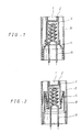
- thermoelectron emissive material is impregnated in a porous base 1 which is made of heat resistance material such as, for example, tungsten.
- the porous base is a thermoelectron emissive source and is contained within a reservoir 2 which is in the form of a cup.
- This reservoir 2 is disposed within the upper portion of a sleeve 3 receiving a heater 6.
- the sleeve 3 is supported by a holder 4 connected to the lower portion thereof, and is enclosed by a large-caliber heat shielding tube 5.
- FIG.2 The construction of another impregnated dispenser cathode illustrated in FIG.2 is similar to the impregnated structure described above.
- This impregnated dispenser cathode comprises a reservoir 2 containing a porous base 1, a sleeve 3 for supporting and fixing the reservoir and receiving a heater 6, a suspending ribbon 8 whose lower portion is welded to the lower end of the sleeve and whose upper portion is welded to the upper end of a large-diameter holder 4, and a heat shielding tube 5 which surrounds the sleeve 3 and is welded to the holder 4.
- thermoelectron emissive source of the cavity reservoir type cathode comprises thermoelectron emissive material such as, for example, tungsten, barium calcium aluminate, etc. which is contained in the reservoir disposed within the upper portion of the sleeve, and a porous base which is, disposed on the thermoelectron emissive material and is welded to the reservoir.
- the dispenser cathodes having the above-mentioned constructions have much higher current density than that of the ordinary oxide cathode ray tube, so that they are adapted to be used in the electron gun of a large-scale cathode ray tube or a projecting tube, etc.
- the withstand voltage characteristic at the initial operation is poor and the radiating state of the electron beam is unstable.
- thermoelectron emissive source of the conventional dispenser cathode i.e. a porous base, which is positioned adjacent to the first electrode of an electron gun, approaches rapidly to the first electrode at the initial operation. This approach of the porous base 1 to the first electrode results from the structural defect of the cathode.
- the sleeve 3 supported by a holder 4 and receiving a heater 6 therein as shown in FIGS.1 and 2 is thermally expanded by heat from the heater towards the first electrode disposed adjacent to the upper portion of the sleeve, starting from the holder 4 disposed in the lower portion of the sleeve.
- the cut-off voltage for controlling the electron beam varies abnormally. As a result, the white balance of image in the screen fails.
- the thermal deformation of the cathode is considered in a step of control of the cathode ray tube, so as to control the characteristic of the cathode ray tube.
- the control of the cathode ray tube is very complicated, and also the stabilization time of picture quality at the initial operation is lengthened even if the control is carried out comparatively well.
- a dispenser cathode for an electron gun comprising: a reservoir for reserving thermoelectron emissive material; a sleeve which is provided with an outward flange at the top thereof and receives and fixes the reservoir within the upper portion thereof; a heat shielding tube provided with inward flange at the top thereof which is corresponding and overlapped with the flange of the sleeve and is welded thereto; and a holder for supporting and fixing the heat shielding tube.
- a porous base 1 impregnated with thermoelectron emissive material is contained within a reservoir 2.
- the reservoir 2 is inserted into and fixed to the upper portion of a sleeve 3 which is provided with an outward flange 3a at the top thereof and receives a heater 6 therein.
- a heat shielding tube 5 of larger caliber is provided with another flange 5a corresponding to the flange of the sleeve 3 at the top thereof.
- the heat shielding tube 5 encloses the sleeve 3 and is coupled to this sleeve by overlapping and welding the flange 3a with the flange 5a.
- the heat shielding tube 5 is fixed to and supported by a holder 4 disposed below the shielding tube 5.
- a porous base 1 impregnated with thermoelectron emissive material is disposed within a reservoir 2, and the reservoir is inserted into and fixed to the upper portion of a sleeve 3 which is provided with a flange 3a at the top thereof and receives a heater 6 therein. Then, this sleeve 3 is welded and fixed to a large-caliber heat shielding tube 5 which is provided with an inward flange 5a at the top thereof. At this time, the sleeve 3 and the heat shielding tube 5 are connected to each other by the flanges 3a and 5a which are nested and welded to each other. Finally, the heat shielding tube 5 is supported and fixed to a holder 4 by a suspending ribbon 8 the lower end of which is welded to the lower portion of the heat shielding tube 5 and upper end of which is welded to the upper end of the holder 4.
- the flanges 3a and 5a are formed respectively on the sleeve 3 and on the heat shielding tube 5, along the entire top circumferences thereof. But they can be formed locally in such a manner that a plurality of fragmentary flanges 3a' and 5a' are formed at corresponding positions to each other.
- a sleeve subject to a large heat expansion is fixed directly to a heat shielding tube, in such a manner that the top end of the sleeve is fixed to the top end of the heat shielding tube and lower end of the sleeve is kept free. Accordingly, when the sleeve undergoes thermal expansion by heat from the heater, it expands in the opposite direction from the first electrode of an electron gun. As a result, the relative movement between the porous base and the first electrode of an electron gun is minimized.
- the change of the cut-off characteristic in the electron gun can be reduced at the initial operation of the cathode ray tube.
- the initial operation characteristic of the electron gun is stabilized as soon as possible, and the white balance of the image is improved.
- it is possible to manufacture an electron gun having little change of several characteristics at the initial operation and also it is possible to provide a cathode ray tube having stable initial operation characteristic and stable picture quality for the users.
- thermoelectron emissive material is stored in a reservoir and a porous base body is fixed on the thermoelectron emissive material.
Landscapes
- Solid Thermionic Cathode (AREA)
- Electrodes For Cathode-Ray Tubes (AREA)
Applications Claiming Priority (2)
| Application Number | Priority Date | Filing Date | Title |
|---|---|---|---|
| KR1019890020770A KR0147542B1 (ko) | 1989-12-31 | 1989-12-31 | 전자관용 함침형 음극 구조체 |
| KR8920770 | 1989-12-31 |
Publications (3)
| Publication Number | Publication Date |
|---|---|
| EP0436360A2 true EP0436360A2 (de) | 1991-07-10 |
| EP0436360A3 EP0436360A3 (en) | 1991-11-21 |
| EP0436360B1 EP0436360B1 (de) | 1995-04-05 |
Family
ID=19294811
Family Applications (1)
| Application Number | Title | Priority Date | Filing Date |
|---|---|---|---|
| EP90314024A Expired - Lifetime EP0436360B1 (de) | 1989-12-31 | 1990-12-20 | Vorratskathode für eine Elektronenstrahlkanone |
Country Status (5)
| Country | Link |
|---|---|
| US (1) | US5113110A (de) |
| EP (1) | EP0436360B1 (de) |
| JP (1) | JPH04262343A (de) |
| KR (1) | KR0147542B1 (de) |
| DE (1) | DE69018425T2 (de) |
Cited By (6)
| Publication number | Priority date | Publication date | Assignee | Title |
|---|---|---|---|---|
| FR2691577A1 (fr) * | 1992-05-22 | 1993-11-26 | Sony Corp | Ensemble cathode et canon à électrons comportant un tel ensemble. |
| EP0641006A1 (de) * | 1993-08-24 | 1995-03-01 | Samsung Display Devices Co., Ltd. | Kathode für eine Elektronenröhre |
| EP0848405A3 (de) * | 1996-12-11 | 1998-08-05 | Lg Electronics Inc. | Imprägnierte Kathode mit geringem Energieverbrauch für eine Kathodenstrahlröhre |
| FR2762712A1 (fr) * | 1997-04-25 | 1998-10-30 | Thomson Tubes & Displays | Structure de cathode pour tube a rayons cathodiques |
| US6242852B1 (en) | 1998-05-08 | 2001-06-05 | Sony Corporation | Electron gun |
| FR2895144A1 (fr) * | 2005-12-16 | 2007-06-22 | Thomson Licensing Sas | Oeillet de cathode pour canon a electrons |
Families Citing this family (5)
| Publication number | Priority date | Publication date | Assignee | Title |
|---|---|---|---|---|
| FR2741997B1 (fr) * | 1995-12-05 | 1998-01-09 | Thomson Tubes & Displays | Structure de cathode pour tube a rayons cathodiques |
| US20030025435A1 (en) * | 1999-11-24 | 2003-02-06 | Vancil Bernard K. | Reservoir dispenser cathode and method of manufacture |
| CN1956124B (zh) * | 2005-10-27 | 2010-07-21 | 中国科学院电子学研究所 | 高效阴极组件 |
| CN107452577B (zh) * | 2017-06-13 | 2023-05-12 | 湖北汉光科技股份有限公司 | 速调管电子枪薄壁侧热屏零件制造方法 |
| CN110931328B (zh) * | 2019-12-06 | 2022-04-19 | 中国电子科技集团公司第十二研究所 | 一种阴极热子组件 |
Family Cites Families (12)
| Publication number | Priority date | Publication date | Assignee | Title |
|---|---|---|---|---|
| US3159461A (en) * | 1958-10-20 | 1964-12-01 | Bell Telephone Labor Inc | Thermionic cathode |
| NL136982C (de) * | 1961-06-01 | |||
| DE1132256B (de) * | 1961-12-27 | 1962-06-28 | Siemens Ag | Kathode fuer elektrische Entladungsgefaesse und Verfahren zu ihrer Herstellung |
| NL6602973A (de) * | 1966-03-08 | 1967-09-11 | ||
| US3441779A (en) * | 1966-04-06 | 1969-04-29 | Siemens Ag | Cathode having an end face carrier for an emission substance and the production thereof |
| DE1614495B1 (de) * | 1967-04-10 | 1971-03-11 | Siemens Ag | Mittelbar geheizte vorratskathode für elektrische entladungsgefässe |
| DE1614566B1 (de) * | 1967-07-17 | 1970-11-05 | Siemens Ag | Indirekt geheizte Vorratskathode,insbesondere MK-Kathode |
| JPS5146877Y2 (de) * | 1973-08-02 | 1976-11-11 | ||
| US4165473A (en) * | 1976-06-21 | 1979-08-21 | Varian Associates, Inc. | Electron tube with dispenser cathode |
| JPS5652835A (en) * | 1979-10-01 | 1981-05-12 | Hitachi Ltd | Impregnated cathode |
| JPS61183838A (ja) * | 1985-02-08 | 1986-08-16 | Hitachi Ltd | 含浸形カソ−ド |
| US4823044A (en) * | 1988-02-10 | 1989-04-18 | Ceradyne, Inc. | Dispenser cathode and method of manufacture therefor |
-
1989
- 1989-12-31 KR KR1019890020770A patent/KR0147542B1/ko not_active Expired - Fee Related
-
1990
- 1990-12-20 DE DE69018425T patent/DE69018425T2/de not_active Expired - Fee Related
- 1990-12-20 EP EP90314024A patent/EP0436360B1/de not_active Expired - Lifetime
- 1990-12-31 US US07/633,529 patent/US5113110A/en not_active Expired - Lifetime
-
1991
- 1991-01-04 JP JP3010328A patent/JPH04262343A/ja active Pending
Cited By (11)
| Publication number | Priority date | Publication date | Assignee | Title |
|---|---|---|---|---|
| FR2691577A1 (fr) * | 1992-05-22 | 1993-11-26 | Sony Corp | Ensemble cathode et canon à électrons comportant un tel ensemble. |
| NL9300874A (nl) * | 1992-05-22 | 1993-12-16 | Sony Corp | Kathode-samenstel en elektronenkanon. |
| EP0641006A1 (de) * | 1993-08-24 | 1995-03-01 | Samsung Display Devices Co., Ltd. | Kathode für eine Elektronenröhre |
| EP0848405A3 (de) * | 1996-12-11 | 1998-08-05 | Lg Electronics Inc. | Imprägnierte Kathode mit geringem Energieverbrauch für eine Kathodenstrahlröhre |
| FR2762712A1 (fr) * | 1997-04-25 | 1998-10-30 | Thomson Tubes & Displays | Structure de cathode pour tube a rayons cathodiques |
| WO1998049704A1 (en) * | 1997-04-25 | 1998-11-05 | Thomson Tubes And Displays, S.A. | Cathode structure and electron gun for cathode ray tubes |
| US6369494B1 (en) | 1997-04-25 | 2002-04-09 | Thomson Tubes & Displays, S.A. | Cathode structure and electron gun for cathode ray tubes |
| US6242852B1 (en) | 1998-05-08 | 2001-06-05 | Sony Corporation | Electron gun |
| SG83126A1 (en) * | 1998-05-08 | 2001-09-18 | Sony Corp | Electron gun |
| NL1011975C2 (nl) * | 1998-05-08 | 2004-02-10 | Sony Corp | Elektronenkanon. |
| FR2895144A1 (fr) * | 2005-12-16 | 2007-06-22 | Thomson Licensing Sas | Oeillet de cathode pour canon a electrons |
Also Published As
| Publication number | Publication date |
|---|---|
| KR0147542B1 (ko) | 1998-08-01 |
| DE69018425T2 (de) | 1995-11-09 |
| KR910013350A (ko) | 1991-08-08 |
| US5113110A (en) | 1992-05-12 |
| EP0436360B1 (de) | 1995-04-05 |
| JPH04262343A (ja) | 1992-09-17 |
| DE69018425D1 (de) | 1995-05-11 |
| EP0436360A3 (en) | 1991-11-21 |
Similar Documents
| Publication | Publication Date | Title |
|---|---|---|
| EP0436360B1 (de) | Vorratskathode für eine Elektronenstrahlkanone | |
| US3983443A (en) | Vacuum electron device having directly-heated matrix-cathode-heater assembly | |
| EP0641007A2 (de) | Direkt beheizte Vorratskathodenstruktur | |
| EP0848405B1 (de) | Imprägnierte Kathode mit geringem Energieverbrauch für eine Kathodenstrahlröhre | |
| US5668434A (en) | Directly heated cathode for cathode ray tube | |
| US5289076A (en) | Cathode structure for a cathode ray tube | |
| RU2060569C1 (ru) | Распределительный катод для электронного прожектора | |
| JPH09129179A (ja) | 放電ランプ用電極およびその製造方法 | |
| US5131878A (en) | Process for manufacturing dispenser cathode | |
| US5703429A (en) | Directly heated cathode structure | |
| EP0778604B1 (de) | Kathodenstruktur für eine Kathodenstrahlröhre | |
| GB2262650A (en) | Impregnated dispenser cathode and manufacture thereof. | |
| US5117153A (en) | Cathode structure for electron gun | |
| RU2155409C2 (ru) | Конструкция катода прямого накала и способ ее изготовления (варианты) | |
| EP0534842A1 (de) | Kathodenstruktur für eine Elektronenröhre | |
| US2869017A (en) | Thermionic dispenser cathode | |
| US7071605B2 (en) | Cathode structure for color cathode ray tube | |
| KR920006821Y1 (ko) | 함침형 음극구조체 | |
| KR930007523Y1 (ko) | 함침형 음극 구조체 | |
| KR100230442B1 (ko) | 음극 구조체 단위 유니트 및 이를 이용한 컬러 음극선관용전자총 | |
| JPS5943633Y2 (ja) | 陰極線管陰極構体 | |
| KR920002589Y1 (ko) | 전자관용 음극 구조체 | |
| KR100201144B1 (ko) | 함침형 캐소드의 펠렛 지지구조 | |
| KR100261736B1 (ko) | 음극선관용캐소드구조체 | |
| KR920001569Y1 (ko) | 음극선관용 전자총의 음극구조체 |
Legal Events
| Date | Code | Title | Description |
|---|---|---|---|
| PUAI | Public reference made under article 153(3) epc to a published international application that has entered the european phase |
Free format text: ORIGINAL CODE: 0009012 |
|
| AK | Designated contracting states |
Kind code of ref document: A2 Designated state(s): DE FR GB NL |
|
| PUAL | Search report despatched |
Free format text: ORIGINAL CODE: 0009013 |
|
| AK | Designated contracting states |
Kind code of ref document: A3 Designated state(s): DE FR GB NL |
|
| 17P | Request for examination filed |
Effective date: 19920311 |
|
| 17Q | First examination report despatched |
Effective date: 19930527 |
|
| RAP1 | Party data changed (applicant data changed or rights of an application transferred) |
Owner name: SAMSUNG DISPLAY DEVICES CO., LTD. |
|
| GRAA | (expected) grant |
Free format text: ORIGINAL CODE: 0009210 |
|
| AK | Designated contracting states |
Kind code of ref document: B1 Designated state(s): DE FR GB NL |
|
| REF | Corresponds to: |
Ref document number: 69018425 Country of ref document: DE Date of ref document: 19950511 |
|
| ET | Fr: translation filed | ||
| PLBE | No opposition filed within time limit |
Free format text: ORIGINAL CODE: 0009261 |
|
| STAA | Information on the status of an ep patent application or granted ep patent |
Free format text: STATUS: NO OPPOSITION FILED WITHIN TIME LIMIT |
|
| 26N | No opposition filed | ||
| PGFP | Annual fee paid to national office [announced via postgrant information from national office to epo] |
Ref country code: FR Payment date: 20011212 Year of fee payment: 12 |
|
| PGFP | Annual fee paid to national office [announced via postgrant information from national office to epo] |
Ref country code: GB Payment date: 20011219 Year of fee payment: 12 |
|
| REG | Reference to a national code |
Ref country code: GB Ref legal event code: IF02 |
|
| PG25 | Lapsed in a contracting state [announced via postgrant information from national office to epo] |
Ref country code: GB Free format text: LAPSE BECAUSE OF NON-PAYMENT OF DUE FEES Effective date: 20021220 |
|
| GBPC | Gb: european patent ceased through non-payment of renewal fee |
Effective date: 20021220 |
|
| PG25 | Lapsed in a contracting state [announced via postgrant information from national office to epo] |
Ref country code: FR Free format text: LAPSE BECAUSE OF NON-PAYMENT OF DUE FEES Effective date: 20030901 |
|
| REG | Reference to a national code |
Ref country code: FR Ref legal event code: ST |
|
| PGFP | Annual fee paid to national office [announced via postgrant information from national office to epo] |
Ref country code: NL Payment date: 20071203 Year of fee payment: 18 |
|
| PGFP | Annual fee paid to national office [announced via postgrant information from national office to epo] |
Ref country code: DE Payment date: 20071213 Year of fee payment: 18 |
|
| NLV4 | Nl: lapsed or anulled due to non-payment of the annual fee |
Effective date: 20090701 |
|
| PG25 | Lapsed in a contracting state [announced via postgrant information from national office to epo] |
Ref country code: DE Free format text: LAPSE BECAUSE OF NON-PAYMENT OF DUE FEES Effective date: 20090701 |
|
| PG25 | Lapsed in a contracting state [announced via postgrant information from national office to epo] |
Ref country code: NL Free format text: LAPSE BECAUSE OF NON-PAYMENT OF DUE FEES Effective date: 20090701 |