EP0436021B1 - Plasma-arc cutting machine and a method of controlling the same - Google Patents
Plasma-arc cutting machine and a method of controlling the same Download PDFInfo
- Publication number
- EP0436021B1 EP0436021B1 EP89903797A EP89903797A EP0436021B1 EP 0436021 B1 EP0436021 B1 EP 0436021B1 EP 89903797 A EP89903797 A EP 89903797A EP 89903797 A EP89903797 A EP 89903797A EP 0436021 B1 EP0436021 B1 EP 0436021B1
- Authority
- EP
- European Patent Office
- Prior art keywords
- circuit
- arc
- current
- plasma
- side connection
- Prior art date
- Legal status (The legal status is an assumption and is not a legal conclusion. Google has not performed a legal analysis and makes no representation as to the accuracy of the status listed.)
- Expired - Lifetime
Links
- 238000005520 cutting process Methods 0.000 title claims abstract description 38
- 238000000034 method Methods 0.000 title claims abstract description 20
- 239000003990 capacitor Substances 0.000 claims abstract description 13
- 238000009499 grossing Methods 0.000 claims description 15
- 230000009471 action Effects 0.000 claims description 5
- 230000008878 coupling Effects 0.000 claims description 4
- 238000010168 coupling process Methods 0.000 claims description 4
- 238000005859 coupling reaction Methods 0.000 claims description 4
- 238000007599 discharging Methods 0.000 claims description 2
- 239000000463 material Substances 0.000 abstract 6
- 238000010586 diagram Methods 0.000 description 9
- 238000010891 electric arc Methods 0.000 description 7
- 230000006866 deterioration Effects 0.000 description 5
- 230000015556 catabolic process Effects 0.000 description 4
- 230000007423 decrease Effects 0.000 description 3
- 230000003111 delayed effect Effects 0.000 description 2
- 238000007664 blowing Methods 0.000 description 1
- 230000008859 change Effects 0.000 description 1
- 230000002708 enhancing effect Effects 0.000 description 1
- 238000010438 heat treatment Methods 0.000 description 1
- 230000003287 optical effect Effects 0.000 description 1
- 230000008569 process Effects 0.000 description 1
- 230000004044 response Effects 0.000 description 1
- 238000011144 upstream manufacturing Methods 0.000 description 1
Images


Classifications
-
- B—PERFORMING OPERATIONS; TRANSPORTING
- B23—MACHINE TOOLS; METAL-WORKING NOT OTHERWISE PROVIDED FOR
- B23K—SOLDERING OR UNSOLDERING; WELDING; CLADDING OR PLATING BY SOLDERING OR WELDING; CUTTING BY APPLYING HEAT LOCALLY, e.g. FLAME CUTTING; WORKING BY LASER BEAM
- B23K9/00—Arc welding or cutting
- B23K9/06—Arrangements or circuits for starting the arc, e.g. by generating ignition voltage, or for stabilising the arc
-
- B—PERFORMING OPERATIONS; TRANSPORTING
- B23—MACHINE TOOLS; METAL-WORKING NOT OTHERWISE PROVIDED FOR
- B23K—SOLDERING OR UNSOLDERING; WELDING; CLADDING OR PLATING BY SOLDERING OR WELDING; CUTTING BY APPLYING HEAT LOCALLY, e.g. FLAME CUTTING; WORKING BY LASER BEAM
- B23K10/00—Welding or cutting by means of a plasma
- B23K10/006—Control circuits therefor
-
- H—ELECTRICITY
- H05—ELECTRIC TECHNIQUES NOT OTHERWISE PROVIDED FOR
- H05H—PLASMA TECHNIQUE; PRODUCTION OF ACCELERATED ELECTRICALLY-CHARGED PARTICLES OR OF NEUTRONS; PRODUCTION OR ACCELERATION OF NEUTRAL MOLECULAR OR ATOMIC BEAMS
- H05H1/00—Generating plasma; Handling plasma
- H05H1/24—Generating plasma
- H05H1/26—Plasma torches
- H05H1/32—Plasma torches using an arc
- H05H1/34—Details, e.g. electrodes, nozzles
- H05H1/36—Circuit arrangements
Definitions
- the present invention relates to a plasma arc cutter for cutting workpieces with high precision and high efficiency and a method of controlling the same.
- JP-A-51-78765 discloses a plasma arc cutter having at least an inverter circuit for converting a commercial alternating current into a predetermined high-frequency alternating current, a rectifying circuit connected to an output terminal of said inverter circuit and a smoothing reactor connected in series to said rectifying circuit.
- a further comarable plasma arc cutter is known from JP-A-60-6750.
- Last a method for pilot and main current control is known from JP-A-63-36974.
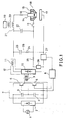
- a commercial alternating current 1 is converted into a direct current by a rectifying circuit 2 composed of a diode.
- the DC output from this rectifying circuit 2 is converted into an alternating current having a predetermined frequency as transistors 5, 6 are alternately switched by base currents alternately output from a control circuit 8 to the bases of the transistors 5, 6 of an inverter circuit 7 composed of capacitors 3, 4 and the transistors 5, 6.
- an AC output of the inverter circuit 7 is transformed by a transformer 9 and is then converted into a DC output capable of stably maintaining an arc discharge by means of a serial circuit 12 composed of a rectifying circuit 10 and a smoothing reactor 11.
- a contact 13 Upon starting of an arc discharge, a contact 13 is closed, and an operating gas is supplied to a gas passage 16 between an electrode 14 and a nozzle 15 of a plasma torch 18.
- the inverter circuit 7 When the operating gas flows, the inverter circuit 7 is actuated, and a voltage which sets the electrode 14 to minus and the nozzle 15 and the workpiece 17 to plus is applied to the plasma torch 18.
- a voltage no-load voltage
- a high-frequency generating circuit 19 is operated, and a high-frequency high voltage is generated at both ends of the secondary coil (electrode-side connection 21) of a coupling coil 20.
- This high-frequency high voltage is applied by a bypass capacitor 22 to between the electrode 14 and the nozzle 15 in such a manner as to be superposed on the aforementioned no-load voltage.
- dielectric breakdown occurs due to a high-frequency discharge, followed by the generation of a pilot arc and then an arc discharge.
- a compensation circuit 28 composed of a capacitor 23 and a resistor 24 is provided in parallel in the serial circuit 12.
- the capacitor 23 is charged up to a no-load voltage produced at the opposite ends of the rectifying circuit 10 at the time when the inverter circuit 7 begins to operate. If the impedance between the electrode 14 and the nozzle 15 declines due to the dielectric breakdown caused by the high-frequency discharge, the capacitor 23 discharges via the resistor 24 and a resistor 25 so as to compensate the serial circuit 12 in whose current rise is slow, thereby allowing a pilot arc to be generated positively.
- the current value of the pilot arc is determined autonomously in such a manner that the voltage of the pilot arc and a voltage drop in the resistor 25 due to the current of the pilot arc are brought into equilibrium with the voltage of the serial circuit 12 thanks to the current and voltage characteristics of the serial circuit 12.
- a current detector 26 is adapted to detect a pilot arc current and stop the high-frequency generating circuit 19.
- the contact 13 is opened, to stop the pilot arc, and a complete main arc discharge follows.
- the main arc discharge is maintained at a fixed level as a signal corresponding to that current is supplied to the control circuit 8 by the current detector 27 and the switching timing of the transistors 5, 6 is subjected to feedback control.
- one plasma torch 18 is provided by using the power source circuit such as the one described above, and, as shown in Fig. 2, such processing as boring (point A1) and cutting (line A2) is performed (piercing start method).
- a method of stopping the arc following two methods are available: (1) a normal cutting completion method in which the power source is stopped while the plasma torch 18 is located above the workpiece 17 so as to extinguish the main arc, as shown in Fig. 3(b), and (2) a forced cutting completion method in which the plasma torch 18 is separated completely from the workpiece, making it impossible to maintain the main arc and thus extinguishing the arc.
- a normal cutting completion method in which the power source is stopped while the plasma torch 18 is located above the workpiece 17 so as to extinguish the main arc
- a forced cutting completion method in which the plasma torch 18 is separated completely from the workpiece, making it impossible to maintain the main arc and thus extinguishing the arc.
- the forced cutting completion method in which point E after passing point B is used as a completion point, is usually employed in such cases.
- a main arc 60 is drawn in the form of a discharge of a normal configuration, and the possibility of the arc being extinguished is small.
- the arc is extinguished after undergoing the state of a double arc 61 (a part or a substantial portion of the current forms a double current path via the nozzle body without passing through the orifice of the nozzle 15), as shown in Fig. 5(b).
- the present invention has been devised in light of the above-described problems, and an object of the present invention is to provide a plasma arc cutter which is capable of cutting workpieces with good precision and high efficiency and a method of controlling the same.
- a plasma arc cutter having an inverter circuit for converting a commercial alternating current into a predetermined high-frequency alternating current, a rectifying circuit connected to an output terminal of the inverter circuit, a smoothing reactor connected in series to the rectifying circuit, an electrode of a plasma torch connected to the cathode side of a serial circuit composed of a rectifying circuit and a smoothing reactor via a coupling coil for generation of an arc starting high-frequency voltage, a workpiece connected to the anode side of the serial circuit, and a nozzle of the plasma torch similarly connected to the anode side via a resistor and a contact, the plasma arc cutter characterised in that, with respect to the serial circuit composed of the rectifying circuit and the smoothing reactor, a rise compensating circuit and a shift compensating circuit both composed of a charging and discharging capacitor and a resistor are respectively inserted in parallel between an electrode-side connection and a
- a detector for controlling a current is provided on the electrode-side connection at a position closer to the electrode side than a connecting point of the rise compensating circuit. Furthermore, a detector for detecting a shift is provided on the workpiece-side connection at a position closer to the workpiece side than the connecting point of the shift compensating circuit.
- a pilot arc is generated on the basis of a current value set by current control, and after a shift from the pilot arc to a main arc takes place, the set current value is changed over to a current value set by the current control of the main arc.
- At the time of effecting piercing for boring and cutting at least one plasma torch for boring and at least one plasma torch for cutting are provided.
- the current of the pilot arc is subjected to current control by the inverter circuit in the same way as the current of the main arc, with the result that the current of the pilot arc is stabilized. Accordingly, it is possible to maintain the pilot arc with a lower current. The amount of heating can consequently be reduced, and the amount of expansion is made small. The flow of the operating gas at the nozzle orifice is made smoother, and the shift from the pilot arc to the main arc is facilitated. Accordingly, the diameter of the nozzle can be reduced, and the stand-off can be increased.
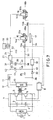
- Fig. 6 is a circuit diagram of a power source for a plasma arc cutter in accordance with a first embodiment of the present invention.
- the components that are identical with those of Fig. 1 which illustrates the conventional art are denoted by the same reference numerals, and a description thereof will be omitted.
- a detector 31 for controlling a current is provided on an electrode-side connection 21 between an electrode 14 and a smoothing reactor 11, and a detector 32 for confirming a shift and a diode 33 are provided on a workpiece-side connection 34 between a workpiece 17 and a rectifying circuit 10.
- a nozzle-side connection 35 is connected to a nozzle 15 and a connecting point 36 provided between the rectifying circuit 10 on a workpiece-side connection 34 and the diode 33, a contact 13 and a resistor 25 being provided in series on the nozzle-side connection 35 itself.
- a capacitor 40 for igniting a pilot arc and a resistor 41 are provided in a rise compensating circuit 39 disposed between a connecting point 37 between the detector 31 on the electrode-side connection 21 and the smoothing reactor 11 on the one hand, and a connecting point 38 on the nozzle-side connection 35 on the other.
- a capacitor 45 for shifting from a pilot arc to a main arc and a resistor 46 are provided in a shift compensating circuit 44 disposed between a connecting point 42 between the detector 31 on the electrode-side connection 21 and the smoothing reactor 11 on the one hand, and a connecting point 43 between the diode 33 on the workpiece-side connection 34 and the detector 32 on the other.
- the discharge current from the shifting capacitor 45 is also detected by the detector 31 and controlled by the control circuit 8 in such a manner that a control current will rise as the discharge current attenuates. As a result, its current value is also maintained at a substantially constant value.
- the two systems of the rise compensating circuit 39 and the shift compensating circuit 44 are provided separately, and the reverse-blocking diode 33 is disposed on the workpiece-side connection 34, the voltage between the electrode 14 and the the workpiece 17 does not fall below no-load voltage, thereby facilitating a shift from the pilot arc to the main arc.
- the shift can be effected smoothly even if the diameter of the orifice in the nozzle 15 is small and the stand-off is high. Furthermore, if the shift from the pilot arc to the main arc is confirmed by the detector 32, the control circuit 8 is changed over to a mode for controlling the current of the main arc, and the discharge current of the main arc is detected by the detector 31 and is fed back to the control circuit 8.
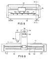
- Figs. 7 to 9 are a circuit diagram of a power source for a plasma arc cutter in accordance with a second embodiment of the present invention, a front elevational view of the cutter, and a cross-sectional view thereof, respectively.
- a plasma torch 18a used exclusively for boring and a plasma torch 18b used exclusively for cutting are provided, electrodes 14a, 14b of the plasma torches 18a, 18b being connected to the electrode-side connection 21.
- Nozzles 15a, 15b are connected to the nozzle-side connection 35 via contacts 13a, 13b, respectively.
- the contacts 13a, 13b are opened and closed in response to signals from the control circuit 8.
- the plasma torches 18a, 18b are juxtaposed on a torch mounting shaft 51 and are adapted to slide in the X-direction along rails 53 by means of a ball screw for torches.
- the rails 53 are secured to a moving frame 54 which is adapted to slide in the Y-direction by means of a moving ball screw 57 along a guide 56 fixed on a table 55.
- the control circuit 8 first supplies a signal to the contact 13a for the plasma torch 18a used exclusively for boring so as to close the same. Then, in the same way as the first embodiment, a shift takes place from the pilot arc to the main arc, and boring is performed. At the time of completion of boring, a change in the discharge current is detected by the detector 31, and the control circuit 8 supplies a signal to the contact 13a to open the same, thereby stopping energization of the plasma torch 18a used exclusively for boring.
- the torch mounting shaft 51 and the moving frame 54 are moved by predetermined amounts, and the plasma torch 18b used exclusively for cutting is moved to the boring completed position.
- the control circuit 8 supplies a signal to the contact 13b for the plasma torch 18b used exclusively for cutting so as to close the same. Then, in the same way as the first embodiment, a shift takes place from the pilot arc to the main arc, and cutting is performed.
- the workpiece 17 placed on the table 55 and connected to the workpiece-side connection 34 can be processed with good precision and high efficiency in an integrated process covering boring and cutting.
- the plasma torch is moved in the X- and Y-directions by means of the ball screws, a motor and an encoder may be used alternatively.
- boring is detected by the current detector, it may be detected by placing an optical sensor, a temperature sensor, etc., below the workpiece.
- the contact is provided on only the nozzle-side connection, it goes without saying that the contact may also be provided on the electrode-side connection.
- the circuit of the first embodiment of the present invention is used as a power source circuit, a conventional power source circuit may be used.
- the plasma arc cutter and the method of controlling the same in accordance with the present invention are suitable to cutting a workpiece with high precision and high efficiency.
Abstract
Description
- The present invention relates to a plasma arc cutter for cutting workpieces with high precision and high efficiency and a method of controlling the same.
- JP-A-51-78765 discloses a plasma arc cutter having at least an inverter circuit for converting a commercial alternating current into a predetermined high-frequency alternating current, a rectifying circuit connected to an output terminal of said inverter circuit and a smoothing reactor connected in series to said rectifying circuit. A further comarable plasma arc cutter is known from JP-A-60-6750. Last a method for pilot and main current control is known from JP-A-63-36974.
- For a better understanding of the present invention a conventional plasma arc cutter having a configuration such as the one shown in Fig.1 should be explained first.
- A commercial
alternating current 1 is converted into a direct current by a rectifyingcircuit 2 composed of a diode. The DC output from this rectifyingcircuit 2 is converted into an alternating current having a predetermined frequency astransistors control circuit 8 to the bases of thetransistors inverter circuit 7 composed ofcapacitors 3, 4 and thetransistors inverter circuit 7 is transformed by atransformer 9 and is then converted into a DC output capable of stably maintaining an arc discharge by means of aserial circuit 12 composed of a rectifyingcircuit 10 and asmoothing reactor 11. - Upon starting of an arc discharge, a
contact 13 is closed, and an operating gas is supplied to agas passage 16 between anelectrode 14 and anozzle 15 of aplasma torch 18. When the operating gas flows, theinverter circuit 7 is actuated, and a voltage which sets theelectrode 14 to minus and thenozzle 15 and theworkpiece 17 to plus is applied to theplasma torch 18. At this stage, however, although a voltage (no-load voltage) is produced between theelectrode 14 and thenozzle 15, dielectric breakdown has not occurred, neither a current flows. Then, a high-frequency generating circuit 19 is operated, and a high-frequency high voltage is generated at both ends of the secondary coil (electrode-side connection 21) of acoupling coil 20. This high-frequency high voltage is applied by abypass capacitor 22 to between theelectrode 14 and thenozzle 15 in such a manner as to be superposed on the aforementioned no-load voltage. Thus, dielectric breakdown occurs due to a high-frequency discharge, followed by the generation of a pilot arc and then an arc discharge. - At this time, the rise of a current supplied from the
serial circuit 12 composed of the rectifyingcircuit 10 and thesmoothing reactor 11 is delayed by the action of thesmoothing reactor 11. Accordingly, acompensation circuit 28 composed of acapacitor 23 and aresistor 24 is provided in parallel in theserial circuit 12. Thecapacitor 23 is charged up to a no-load voltage produced at the opposite ends of the rectifyingcircuit 10 at the time when theinverter circuit 7 begins to operate. If the impedance between theelectrode 14 and thenozzle 15 declines due to the dielectric breakdown caused by the high-frequency discharge, thecapacitor 23 discharges via theresistor 24 and aresistor 25 so as to compensate theserial circuit 12 in whose current rise is slow, thereby allowing a pilot arc to be generated positively. In this case, the current value of the pilot arc is determined autonomously in such a manner that the voltage of the pilot arc and a voltage drop in theresistor 25 due to the current of the pilot arc are brought into equilibrium with the voltage of theserial circuit 12 thanks to the current and voltage characteristics of theserial circuit 12. Acurrent detector 26 is adapted to detect a pilot arc current and stop the high-frequency generating circuit 19. When electrical conductance is secured between theelectrode 14 and theworkpiece 17 by being led by a pilot arc, thecapacitor 23 discharges in a main arc circuit constituted by theelectrode 14 and theworkpiece 17 by means of theresistor 24, and then the current of theserial circuit 12 is supplied, thereby continuing the discharge. If the supply of the current from theserial circuit 12 is confirmed by thecurrent detector 27, thecontact 13 is opened, to stop the pilot arc, and a complete main arc discharge follows. The main arc discharge is maintained at a fixed level as a signal corresponding to that current is supplied to thecontrol circuit 8 by thecurrent detector 27 and the switching timing of thetransistors - In addition, conventionally, one
plasma torch 18 is provided by using the power source circuit such as the one described above, and, as shown in Fig. 2, such processing as boring (point A1) and cutting (line A2) is performed (piercing start method). - Furthermore, as a method of stopping the arc, following two methods are available: (1) a normal cutting completion method in which the power source is stopped while the
plasma torch 18 is located above theworkpiece 17 so as to extinguish the main arc, as shown in Fig. 3(b), and (2) a forced cutting completion method in which theplasma torch 18 is separated completely from the workpiece, making it impossible to maintain the main arc and thus extinguishing the arc. However, in cases where theworkpiece 17 is cut off, as shown in Fig. 4(a), or the external configuration is used as a product after the inner configuration is cut off, as shown in Fig. 4(b), if the normal cutting completion method is used, there are cases where an uncut portion is left, and it is difficult to provide a timing for the movement of the plasma torch and a stop signal for the power source. Accordingly, the forced cutting completion method, in which point E after passing point B is used as a completion point, is usually employed in such cases. According to this method, as shown in Fig. 5(a), amain arc 60 is drawn in the form of a discharge of a normal configuration, and the possibility of the arc being extinguished is small. In many cases, the arc is extinguished after undergoing the state of a double arc 61 (a part or a substantial portion of the current forms a double current path via the nozzle body without passing through the orifice of the nozzle 15), as shown in Fig. 5(b). - In cutting a workpiece with high precision and high efficiency by using such a plasma arc cutter, the following points are desirable:
- (1) The diameter of the orifice is made small so as to restrict the arc, thereby enhancing the current density of the arc.
- (2) The amount of dross adhering to the nozzle is kept to a minimum.
- (3) The occurrence of a double arc, which results in the deterioration of the nozzle and a decline in cutting quality, is prevented.
- With the conventional art, however, the following problems are encountered:
- (1) Following a high-frequency discharge, a pilot arc is ignited, but a nozzle-side arc arrival point is located upstream of the orifice, is blown to the downstream side by the current of the working gas, passes through the orifice and moves to the main arc. In this case, if the diameter of the orifice is small, when the pilot arc is ignited, the working gas expands suddenly by the heat caused by the arc. Hence, the flow rate of the gas at the orifice declines, and the action of the gas current moving the arc arrival point declines, thereby delaying a shift from the pilot arc to the main arc. Since the pilot arc causes an arc discharge by using the nozzle as an anode, deterioration of the nozzle is entailed. Therefore, if the shift to the arc discharge is delayed, the deterioration of the nozzle advances, resulting in a decline in the cutting performance. If the starting of such an arc is repeated, the deterioration of the nozzle advances rapidly, it is difficult to reduce the diameter of the orifice in the nozzle.
- (2) In order to prevent the dross from being blown up and being attached to the nozzle, the distance (i.e., stand-off) between the workpiece and the plasma torch may be made larger than at the time of cutting in a steady state. However, if the stand-off is made large, the shift from the pilot arc to the main arc becomes difficult, so there are limitations to making the stand-off large.
- (3) The invention of Japanese Patent Laid-Open No. 24864/1987 has been proposed as a method of detecting the limit of using an electrode by paying attention to voltage fluctuations entailed by the deterioration of the electrode. However, at present no appropriate means can be found for preventing in advance the occurrence of the double arc itself.
- The present invention has been devised in light of the above-described problems, and an object of the present invention is to provide a plasma arc cutter which is capable of cutting workpieces with good precision and high efficiency and a method of controlling the same.
- Accordingly, in accordance with a plasma arc cutter and a method of controlling the same, there is provided a plasma arc cutter having an inverter circuit for converting a commercial alternating current into a predetermined high-frequency alternating current, a rectifying circuit connected to an output terminal of the inverter circuit, a smoothing reactor connected in series to the rectifying circuit, an electrode of a plasma torch connected to the cathode side of a serial circuit composed of a rectifying circuit and a smoothing reactor via a coupling coil for generation of an arc starting high-frequency voltage, a workpiece connected to the anode side of the serial circuit, and a nozzle of the plasma torch similarly connected to the anode side via a resistor and a contact, the plasma arc cutter characterised in that, with respect to the serial circuit composed of the rectifying circuit and the smoothing reactor, a rise compensating circuit and a shift compensating circuit both composed of a charging and discharging capacitor and a resistor are respectively inserted in parallel between an electrode-side connection and a nozzle-side connection and between the electrode-side connection and a workpiece-side connection, and that a diode is provided on the workpiece-side connection in such a manner as to be inserted between a connecting point of the nozzle-side connection and a connecting point of the shift compensating circuit. In addition, a detector for controlling a current is provided on the electrode-side connection at a position closer to the electrode side than a connecting point of the rise compensating circuit. Furthermore, a detector for detecting a shift is provided on the workpiece-side connection at a position closer to the workpiece side than the connecting point of the shift compensating circuit.
- A pilot arc is generated on the basis of a current value set by current control, and after a shift from the pilot arc to a main arc takes place, the set current value is changed over to a current value set by the current control of the main arc.
- In addition, at the time of effecting piercing for boring and cutting, at least one plasma torch for boring and at least one plasma torch for cutting are provided.
- By virtue of the above-described arrangement, the current of the pilot arc is subjected to current control by the inverter circuit in the same way as the current of the main arc, with the result that the current of the pilot arc is stabilized. Accordingly, it is possible to maintain the pilot arc with a lower current. The amount of heating can consequently be reduced, and the amount of expansion is made small. The flow of the operating gas at the nozzle orifice is made smoother, and the shift from the pilot arc to the main arc is facilitated. Accordingly, the diameter of the nozzle can be reduced, and the stand-off can be increased.
- In addition, the possibility of cutting being effected by using a plasma torch damaged by the blowing up at the time of boring can be reduced substantially to nil, with the result that cutting precision is increased.
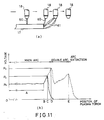
- Moreover, if the distance between the plasma torch and the workpiece becomes large after completion of cutting, the main arc is drawn and the voltage rises sharply. When the voltage exceeds a limit, the arc shifts to a double arc, causing the voltage to decline. When that distance becomes far larger, the voltage rises again, but it becomes impossible to maintain the discharge by even the double arc (broken line in Fig. 11(b)) and the arc is thereby extinguished. Accordingly, it is possible to prevent the occurrence of a double arc if the power source is stopped by detecting voltage PC (PC < PD) after voltage PB rises sharply upon completion of cutting and before it reaches limit PD for generation of a double arc.
-
- Fig. 1 is a circuit diagram of a power source for a plasma arc cutter in accordance with the conventional art;
- Fig. 2 is a diagram illustrating the boring and cutting of a workpiece by means of a plasma arc;
- Figs. 3(a) and 3(b) are conceptual diagrams at the time of completion of plasma arc cutting in accordance with the conventional art;
- Fig. 4(a) and 4(b) are conceptual diagrams of a conventional plasma arc cutting process;
- Figs. 5(a) and 5(b) are conceptual diagrams illustrating the occurrence of a double arc in accordance with the conventional plasma arc cutting process;
- Fig. 6 is a circuit diagram of a power source for a plasma arc cutter in accordance with a first embodiment of the present invention;
- Fig. 7 is a circuit diagram of a power source for a plasma arc cutter in accordance with a second embodiment of the present invention;
- Fig. 8 is a front elevational view of the plasma arc cutter in accordance with the second embodiment of the present invention;
- Fig. 9 is a cross-sectional view taken along the line IX-IX of Fig. 8;
- Fig. 6 is a circuit diagram of a power source for a plasma arc cutter in accordance with a first embodiment of the present invention. The components that are identical with those of Fig. 1 which illustrates the conventional art are denoted by the same reference numerals, and a description thereof will be omitted.
- In Fig. 6, a
detector 31 for controlling a current is provided on an electrode-side connection 21 between anelectrode 14 and a smoothingreactor 11, and adetector 32 for confirming a shift and adiode 33 are provided on a workpiece-side connection 34 between a workpiece 17 and a rectifyingcircuit 10. A nozzle-side connection 35 is connected to anozzle 15 and a connectingpoint 36 provided between the rectifyingcircuit 10 on a workpiece-side connection 34 and thediode 33, acontact 13 and aresistor 25 being provided in series on the nozzle-side connection 35 itself. Acapacitor 40 for igniting a pilot arc and aresistor 41 are provided in arise compensating circuit 39 disposed between a connectingpoint 37 between thedetector 31 on the electrode-side connection 21 and the smoothingreactor 11 on the one hand, and a connectingpoint 38 on the nozzle-side connection 35 on the other. In addition, acapacitor 45 for shifting from a pilot arc to a main arc and aresistor 46 are provided in ashift compensating circuit 44 disposed between a connectingpoint 42 between thedetector 31 on the electrode-side connection 21 and the smoothingreactor 11 on the one hand, and a connectingpoint 43 between thediode 33 on the workpiece-side connection 34 and thedetector 32 on the other. - The operation will be described below on the basis of the above-described arrangement. At the time of starting, a pilot arc is generated after dielectric breakdown takes place due to a high-frequency discharge. However, since the rise in a current takes place by means of the exclusively provided rise compensating
circuit 39, the rise can be effected smoothly without any delay. At this juncture, a discharge current from the pilotarc igniting capacitor 40 is detected by thedetector 31 and controlled by acontrol circuit 8 in such a manner that a control current will rise as the discharge current attenuates. Accordingly, its current value is maintained at a substantially constant value without excessively exceeding a preset value. Subsequently, during a shift from a pilot arc to a main arc, the discharge current from the shiftingcapacitor 45 is also detected by thedetector 31 and controlled by thecontrol circuit 8 in such a manner that a control current will rise as the discharge current attenuates. As a result, its current value is also maintained at a substantially constant value. In addition, since the two systems of therise compensating circuit 39 and theshift compensating circuit 44 are provided separately, and the reverse-blockingdiode 33 is disposed on the workpiece-side connection 34, the voltage between theelectrode 14 and the theworkpiece 17 does not fall below no-load voltage, thereby facilitating a shift from the pilot arc to the main arc. The shift can be effected smoothly even if the diameter of the orifice in thenozzle 15 is small and the stand-off is high. Furthermore, if the shift from the pilot arc to the main arc is confirmed by thedetector 32, thecontrol circuit 8 is changed over to a mode for controlling the current of the main arc, and the discharge current of the main arc is detected by thedetector 31 and is fed back to thecontrol circuit 8. - Figs. 7 to 9 are a circuit diagram of a power source for a plasma arc cutter in accordance with a second embodiment of the present invention, a front elevational view of the cutter, and a cross-sectional view thereof, respectively. In Fig. 7, a
plasma torch 18a used exclusively for boring and aplasma torch 18b used exclusively for cutting are provided,electrodes 14a, 14b of the plasma torches 18a, 18b being connected to the electrode-side connection 21.Nozzles side connection 35 viacontacts contacts control circuit 8. - In Figs. 8 and 9, the plasma torches 18a, 18b are juxtaposed on a
torch mounting shaft 51 and are adapted to slide in the X-direction alongrails 53 by means of a ball screw for torches. Therails 53 are secured to a movingframe 54 which is adapted to slide in the Y-direction by means of a movingball screw 57 along aguide 56 fixed on a table 55. - The operation will be described hereafter on the basis of the above-described arrangement. At the time of processing the
workpiece 17, thecontrol circuit 8 first supplies a signal to thecontact 13a for theplasma torch 18a used exclusively for boring so as to close the same. Then, in the same way as the first embodiment, a shift takes place from the pilot arc to the main arc, and boring is performed. At the time of completion of boring, a change in the discharge current is detected by thedetector 31, and thecontrol circuit 8 supplies a signal to thecontact 13a to open the same, thereby stopping energization of theplasma torch 18a used exclusively for boring. Thetorch mounting shaft 51 and the movingframe 54 are moved by predetermined amounts, and theplasma torch 18b used exclusively for cutting is moved to the boring completed position. After a predetermined period of movement has elapsed, thecontrol circuit 8 supplies a signal to thecontact 13b for theplasma torch 18b used exclusively for cutting so as to close the same. Then, in the same way as the first embodiment, a shift takes place from the pilot arc to the main arc, and cutting is performed. By virtue of movement in the X- and Y-directions, theworkpiece 17 placed on the table 55 and connected to the workpiece-side connection 34 can be processed with good precision and high efficiency in an integrated process covering boring and cutting. - It should be noted that although the plasma torch is moved in the X- and Y-directions by means of the ball screws, a motor and an encoder may be used alternatively. Although boring is detected by the current detector, it may be detected by placing an optical sensor, a temperature sensor, etc., below the workpiece. In addition, although the contact is provided on only the nozzle-side connection, it goes without saying that the contact may also be provided on the electrode-side connection. Furthermore, although the circuit of the first embodiment of the present invention is used as a power source circuit, a conventional power source circuit may be used.
- As described above, in the plasma arc cutter and the method of controlling the same in accordance with the present invention, a shift from the pilot arc to the main arc is facilitated, and the diameter of the nozzle orifice can be made small. Accordingly, the current density can be enhanced, and the stand-off can be set to a high level. In addition, the possibility of cutting being effected by using a plasma torch damaged during boring is reduced substantially to nil, and the occurrence of a double arc during cutting is prevented, the plasma arc cutter and the method of controlling the same in accordance with the present invention are suitable to cutting a workpiece with high precision and high efficiency.
Claims (3)
- A plasma arc cutter having an inverter circuit for converting a commercial alternating current into a predetermined high-frequency alternating current, a rectifying circuit connected to an output terminal of said inverter circuit, a smoothing reactor connected in series to said rectifying circuit, an electrode of a plasma torch connected to the cathode side of a serial circuit composed of a rectifying circuit and a smoothing reactor via a coupling coil for generation of an arc starting high-frequency voltage, a workpiece connected to the anode side of said aerial circuit, and a nozzle of said plasma torch similarly connected to said anode side via a resistor and a contact, said plasma arc cutter characterised in that, with respect to said serial circuit composed of said rectifying circuit and said smoothing reactor, a rise compensating circuit and a shift compensating circuit both composed of a charging and discharging capacitor and a resistor are respectively inserted in parallel between an electrode-side connection and a nozzle-side connection and between said electrode-side connection and a workpiece-side connection, that a diode is provided on said workpiece-side connection in such a manner as to be inserted between a connecting point of said nozzle-side connection and a connecting point of said shift compensating circuit, that a detector for controlling a current is provided on said electrode side connection at a position closer to the electrode side than a connecting point of said rise compensating circuit, and that a detector for detecting a shift is provided on said workpiece-side connection at a position closer to the workpiece side than said connecting point of said shift compensating circuit.
- A plasma arc cutter according to claim 1,
characterized in that at least one plasma torch for boring and at least one plasma torch for cutting are provided to the effect boring and cutting. - A method of controlling a plasma arc cutter having an inverter circuit for converting a commercial alternating current into a predetermined high-frequency alternating current, a rectifying circuit connected to an output terminal of said inverter circuit, a smoothing reactor connected in series to said rectifying circuit, an electrode of a plasma torch connected to the cathode side of a serial circuit composed of a rectifying circuit and a smoothing reactor via a coupling coil for generation of an arc starting high-frequency voltage, a workpiece connected to the anode side of said serial circuit, and a nozzle of said plasma torch similarly connected to said anode side via a resistor and a contact, said method of controlling a plasma arc cutter characterized in that a pilot arc is generated on the basis of a current value set by a current control corresponding to each action of a rise compensating circuit and a detector for controlling a current, that a shift from said pilot arc to a main arc is taken on the basis of a current value set by the current control corresponding each action of a shift compensating circuit and a detector for detecting a shift and that said main arc is controlled on the basis of a current value set by the current control of said main arc corresponding to an action of the detector for controlling a current.
Priority Applications (1)
| Application Number | Priority Date | Filing Date | Title |
|---|---|---|---|
| EP96250051A EP0722805A1 (en) | 1988-03-24 | 1989-03-23 | Method of controlling a plasma arc cutter |
Applications Claiming Priority (5)
| Application Number | Priority Date | Filing Date | Title |
|---|---|---|---|
| JP70079/88 | 1988-03-24 | ||
| JP63070079A JPH0688141B2 (en) | 1988-03-24 | 1988-03-24 | Double arc prevention cutting method in plasma arc cutting |
| JP1273/87 | 1988-05-24 | ||
| JP63127387A JPH0661628B2 (en) | 1988-05-24 | 1988-05-24 | Plasma arc cutting machine and control method thereof |
| PCT/JP1989/000305 WO1989009110A1 (en) | 1988-03-24 | 1989-03-23 | Plasma-arc cutting machine and a method of controlling the same |
Related Child Applications (1)
| Application Number | Title | Priority Date | Filing Date |
|---|---|---|---|
| EP96250051.8 Division-Into | 1989-03-23 |
Publications (3)
| Publication Number | Publication Date |
|---|---|
| EP0436021A4 EP0436021A4 (en) | 1990-10-18 |
| EP0436021A1 EP0436021A1 (en) | 1991-07-10 |
| EP0436021B1 true EP0436021B1 (en) | 1996-09-25 |
Family
ID=26411237
Family Applications (2)
| Application Number | Title | Priority Date | Filing Date |
|---|---|---|---|
| EP96250051A Withdrawn EP0722805A1 (en) | 1988-03-24 | 1989-03-23 | Method of controlling a plasma arc cutter |
| EP89903797A Expired - Lifetime EP0436021B1 (en) | 1988-03-24 | 1989-03-23 | Plasma-arc cutting machine and a method of controlling the same |
Family Applications Before (1)
| Application Number | Title | Priority Date | Filing Date |
|---|---|---|---|
| EP96250051A Withdrawn EP0722805A1 (en) | 1988-03-24 | 1989-03-23 | Method of controlling a plasma arc cutter |
Country Status (5)
| Country | Link |
|---|---|
| US (1) | US5036176A (en) |
| EP (2) | EP0722805A1 (en) |
| KR (1) | KR0137030B1 (en) |
| DE (1) | DE68927261T2 (en) |
| WO (1) | WO1989009110A1 (en) |
Families Citing this family (39)
| Publication number | Priority date | Publication date | Assignee | Title |
|---|---|---|---|---|
| JP2523000B2 (en) * | 1988-10-20 | 1996-08-07 | 株式会社小松製作所 | Plate material processing method for plasma cutting machine and plasma torch |
| EP0795372A1 (en) * | 1990-04-17 | 1997-09-17 | Kabushiki Kaisha Komatsu Seisakusho | Standoff control method and apparatus for plasma cutting machine |
| US5170030A (en) * | 1991-04-08 | 1992-12-08 | Thermal Dynamics Corporation | Plasma torch electronic pulsing circuit |
| USRE37608E1 (en) * | 1991-04-08 | 2002-03-26 | Thermal Dynamics Corporation | Plasma torch electronic pulsing circuit |
| US5183990A (en) * | 1991-04-12 | 1993-02-02 | The Lincoln Electric Company | Method and circuit for protecting plasma nozzle |
| EP0604553B1 (en) * | 1991-09-18 | 1997-07-09 | Thermal Dynamics Corporation | Plasma torch electronic circuit |
| US5290995A (en) * | 1991-12-20 | 1994-03-01 | Esab Welding Products, Inc. | Plasma arc cutting system having fluid metering and power control systems |
| US5296665A (en) * | 1992-05-19 | 1994-03-22 | Hypertherm, Inc. | Method of restarting a plasma arc torch using a periodic high frequency-high voltage signal |
| US5416297A (en) * | 1993-03-30 | 1995-05-16 | Hypertherm, Inc. | Plasma arc torch ignition circuit and method |
| US5605039A (en) * | 1993-07-15 | 1997-02-25 | Olin Corporation | Parallel arcjet starter system |
| US5513087A (en) * | 1993-07-15 | 1996-04-30 | Olin Corporation | Arcjet startup using a shunt output high voltage pulse circuit |
| US5530220A (en) * | 1994-04-11 | 1996-06-25 | Thermal Dynamics Corporation | Plasma torch arc transfer circuit |
| JP3300240B2 (en) * | 1996-12-18 | 2002-07-08 | 株式会社三社電機製作所 | DC arc start circuit |
| US5866869A (en) * | 1997-02-24 | 1999-02-02 | Illinois Tool Works Inc. | Plasma pilot arc control |
| US5831237A (en) * | 1997-03-13 | 1998-11-03 | The Lincoln Electric Company | Plasma arc power system and method of operating same |
| US5847354A (en) * | 1997-03-18 | 1998-12-08 | The Lincoln Electric Company | Arc transfer circuit |
| US5893986A (en) * | 1997-04-11 | 1999-04-13 | The Esab Group, Inc. | Method of controlling a plasma arc cutting torch |
| US5900169A (en) * | 1997-06-06 | 1999-05-04 | Hypertherm, Inc. | Safety circuit for a blow forward contact start plasma arc torch |
| US5844197A (en) * | 1997-07-28 | 1998-12-01 | The Lincoln Electric Company | Arc retract circuit and method |
| US5990443A (en) * | 1998-03-12 | 1999-11-23 | Thermal Dynamics Corporation | Plasma torch pilot arc circuit |
| GB9825452D0 (en) * | 1998-11-21 | 1999-01-13 | Arc Kinetics Ltd | Improved welding apparatus and method |
| US6329628B1 (en) * | 1998-12-10 | 2001-12-11 | Polytechnic University | Methods and apparatus for generating a plasma torch |
| US6153850A (en) | 1999-04-29 | 2000-11-28 | The Esab Group, Inc. | Method of cutting a workpiece along an arcuate path with a plasma arc torch |
| US6236014B1 (en) * | 1999-12-20 | 2001-05-22 | Illinois Tool Works Inc. | Method and apparatus for providing welding/plasma power |
| US6222155B1 (en) | 2000-06-14 | 2001-04-24 | The Esab Group, Inc. | Cutting apparatus with thermal and nonthermal cutters, and associated methods |
| US6794601B2 (en) * | 2002-09-05 | 2004-09-21 | Thermal Dynamics Corporation | Plasma arc torch system with pilot re-attach circuit and method |
| US7022935B1 (en) | 2003-12-08 | 2006-04-04 | Illinois Tool Works Inc. | Plasma-cutting torch with integrated high frequency starter |
| US7091441B1 (en) * | 2004-03-19 | 2006-08-15 | Polytechnic University | Portable arc-seeded microwave plasma torch |
| EP2324975B1 (en) * | 2004-04-01 | 2016-12-21 | PicoDrill SA | Manufacturing and use of microperforated substrates |
| US7087856B2 (en) * | 2004-11-03 | 2006-08-08 | The Esab Group, Inc. | System and method for determining an operational condition of a torch |
| US20070045241A1 (en) * | 2005-08-29 | 2007-03-01 | Schneider Joseph C | Contact start plasma torch and method of operation |
| DE102007010996A1 (en) * | 2007-03-05 | 2008-09-11 | Arcoron Gmbh | plasma nozzle |
| US20140203005A1 (en) * | 2013-01-23 | 2014-07-24 | Gordon R. Hanka | Welder powered arc starter |
| US20160121418A1 (en) * | 2012-01-25 | 2016-05-05 | Gordon Hanka | Welder Powered Arc Starter |
| JP6811236B2 (en) | 2015-10-06 | 2021-01-13 | ハイパーサーム インコーポレイテッド | Plasma arc torch control and related systems and methods |
| US10279417B2 (en) | 2015-10-06 | 2019-05-07 | Hypertherm, Inc. | Controlling and delivering gases in a plasma arc torch and related systems and methods |
| US9833860B1 (en) | 2016-07-22 | 2017-12-05 | Lincoln Global, Inc. | System and method for plasma arc transfer for plasma cutting |
| WO2018098057A1 (en) * | 2016-11-22 | 2018-05-31 | Mestek Machinery, Inc. | Method and apparatus for manipulating metal workpieces |
| US10322466B2 (en) * | 2017-02-23 | 2019-06-18 | Lincoln Global, Inc. | Enhanced piercing and operation of plasma cutting torch and system |
Family Cites Families (14)
| Publication number | Priority date | Publication date | Assignee | Title |
|---|---|---|---|---|
| GB1090404A (en) * | 1963-07-25 | 1967-11-08 | British Oxygen Co Ltd | Means for initiating electric arcs between spaced electrodes |
| JPS5120020B2 (en) * | 1971-09-10 | 1976-06-22 | ||
| US3909664A (en) * | 1973-09-17 | 1975-09-30 | Outboard Marine Corp | Plasma spraying method and apparatus |
| JPS5120020A (en) * | 1974-08-12 | 1976-02-17 | Kawasaki Heavy Ind Ltd | IGATAYOSOSEI BUTSU |
| US4017707A (en) * | 1974-12-04 | 1977-04-12 | Caterpillar Tractor Co. | Method of and means for spacing control of plasma arc torch |
| JPS51143547A (en) * | 1975-06-05 | 1976-12-09 | Mitsubishi Electric Corp | Method of initiating arc |
| JPS5244584Y2 (en) * | 1976-04-30 | 1977-10-11 | ||
| DE2706232C3 (en) * | 1977-02-15 | 1980-10-23 | Messer Griesheim Gmbh, 6000 Frankfurt | Method for keeping the distance of a tool constant from a workpiece to be machined and device for its implementation |
| JPS6340313Y2 (en) * | 1980-05-31 | 1988-10-21 | ||
| JPS606750B2 (en) * | 1982-10-22 | 1985-02-20 | トヨタ自動車株式会社 | automatic fusing machine |
| JPS6320166A (en) * | 1986-07-14 | 1988-01-27 | Hitachi Seiko Ltd | Power source for plasma arc |
| JPS6336974A (en) * | 1986-07-30 | 1988-02-17 | Hitachi Seiko Ltd | Power source for plasma arc |
| JPS63268572A (en) * | 1987-04-27 | 1988-11-07 | Inoue Japax Res Inc | Plasma generating device |
| US4839499A (en) * | 1988-06-13 | 1989-06-13 | Cyclomatic Industries, Inc. | System for supplying power to different cutting torches |
-
1989
- 1989-03-23 EP EP96250051A patent/EP0722805A1/en not_active Withdrawn
- 1989-03-23 EP EP89903797A patent/EP0436021B1/en not_active Expired - Lifetime
- 1989-03-23 DE DE68927261T patent/DE68927261T2/en not_active Expired - Fee Related
- 1989-03-23 US US07/427,106 patent/US5036176A/en not_active Expired - Fee Related
- 1989-03-23 WO PCT/JP1989/000305 patent/WO1989009110A1/en active IP Right Grant
- 1989-09-29 KR KR89701808A patent/KR0137030B1/en not_active IP Right Cessation
Also Published As
| Publication number | Publication date |
|---|---|
| DE68927261D1 (en) | 1996-10-31 |
| KR900700249A (en) | 1990-08-11 |
| US5036176A (en) | 1991-07-30 |
| EP0436021A4 (en) | 1990-10-18 |
| EP0436021A1 (en) | 1991-07-10 |
| KR0137030B1 (en) | 1998-07-01 |
| DE68927261T2 (en) | 1997-02-06 |
| EP0722805A1 (en) | 1996-07-24 |
| WO1989009110A1 (en) | 1989-10-05 |
Similar Documents
| Publication | Publication Date | Title |
|---|---|---|
| EP0436021B1 (en) | Plasma-arc cutting machine and a method of controlling the same | |
| US5225658A (en) | Stopping a plasma arc cutter upon completion of cutting | |
| EP0951961B1 (en) | Plasma pilot arc control | |
| US5506384A (en) | Plasma arc cutting machine with variable constant current source and variable resistor | |
| US4280042A (en) | Process and installation for automatic ignition of a plasma cutting torch | |
| US5530220A (en) | Plasma torch arc transfer circuit | |
| JP3652350B2 (en) | Plasma processing method | |
| EP0200499A1 (en) | Method of igniting arcs | |
| WO1993006702A1 (en) | Plasma torch electronic circuit | |
| JPH01299771A (en) | Plasma arc cutting machine and its control method | |
| SU1743752A1 (en) | Consumable-electrode arc welder | |
| KR930001516B1 (en) | Method of automatically controlling the starting height of a burner | |
| EP1131181B1 (en) | Improved welding apparatus and method | |
| US3997756A (en) | Method for striking main arc between the electrode of plasmatron and workpiece, and contrivance embodying same | |
| JP6260007B2 (en) | EDM system | |
| JPH036868B2 (en) | ||
| JP2000094126A (en) | Dc arc welding device and arc ignition device of plasma working equipment | |
| JPS59202168A (en) | Starting method of plasma arc | |
| JPS63149078A (en) | Arc discharge device | |
| JP3220616B2 (en) | Plasma arc transfer type cutting device | |
| JPH0618708Y2 (en) | Plasma arc processing equipment | |
| JPH01254384A (en) | Plasma arc cutter | |
| JPH0333069B2 (en) | ||
| JPS61249674A (en) | Arc ignition method in nonconsumable electrode type arc welding | |
| RU2022736C1 (en) | Automatic control device for energizing plasma generator |
Legal Events
| Date | Code | Title | Description |
|---|---|---|---|
| PUAI | Public reference made under article 153(3) epc to a published international application that has entered the european phase |
Free format text: ORIGINAL CODE: 0009012 |
|
| 17P | Request for examination filed |
Effective date: 19900426 |
|
| AK | Designated contracting states |
Kind code of ref document: A1 Designated state(s): DE FR GB |
|
| 17Q | First examination report despatched |
Effective date: 19930628 |
|
| GRAH | Despatch of communication of intention to grant a patent |
Free format text: ORIGINAL CODE: EPIDOS IGRA |
|
| GRAH | Despatch of communication of intention to grant a patent |
Free format text: ORIGINAL CODE: EPIDOS IGRA |
|
| GRAA | (expected) grant |
Free format text: ORIGINAL CODE: 0009210 |
|
| DX | Miscellaneous (deleted) | ||
| AK | Designated contracting states |
Kind code of ref document: B1 Designated state(s): DE FR GB |
|
| ET | Fr: translation filed | ||
| REF | Corresponds to: |
Ref document number: 68927261 Country of ref document: DE Date of ref document: 19961031 |
|
| PLBE | No opposition filed within time limit |
Free format text: ORIGINAL CODE: 0009261 |
|
| STAA | Information on the status of an ep patent application or granted ep patent |
Free format text: STATUS: NO OPPOSITION FILED WITHIN TIME LIMIT |
|
| 26N | No opposition filed | ||
| PGFP | Annual fee paid to national office [announced via postgrant information from national office to epo] |
Ref country code: FR Payment date: 19990309 Year of fee payment: 11 |
|
| PGFP | Annual fee paid to national office [announced via postgrant information from national office to epo] |
Ref country code: GB Payment date: 19990325 Year of fee payment: 11 |
|
| PGFP | Annual fee paid to national office [announced via postgrant information from national office to epo] |
Ref country code: DE Payment date: 20000318 Year of fee payment: 12 |
|
| PG25 | Lapsed in a contracting state [announced via postgrant information from national office to epo] |
Ref country code: GB Free format text: LAPSE BECAUSE OF NON-PAYMENT OF DUE FEES Effective date: 20000323 |
|
| GBPC | Gb: european patent ceased through non-payment of renewal fee |
Effective date: 20000323 |
|
| PG25 | Lapsed in a contracting state [announced via postgrant information from national office to epo] |
Ref country code: FR Free format text: LAPSE BECAUSE OF NON-PAYMENT OF DUE FEES Effective date: 20001130 |
|
| REG | Reference to a national code |
Ref country code: FR Ref legal event code: ST |
|
| PG25 | Lapsed in a contracting state [announced via postgrant information from national office to epo] |
Ref country code: DE Free format text: LAPSE BECAUSE OF NON-PAYMENT OF DUE FEES Effective date: 20020101 |