EP0435587B1 - Multi-axle air suspension system for a vehicle - Google Patents
Multi-axle air suspension system for a vehicle Download PDFInfo
- Publication number
- EP0435587B1 EP0435587B1 EP19900314050 EP90314050A EP0435587B1 EP 0435587 B1 EP0435587 B1 EP 0435587B1 EP 19900314050 EP19900314050 EP 19900314050 EP 90314050 A EP90314050 A EP 90314050A EP 0435587 B1 EP0435587 B1 EP 0435587B1
- Authority
- EP
- European Patent Office
- Prior art keywords
- valve means
- air
- axle
- vehicle
- air springs
- Prior art date
- Legal status (The legal status is an assumption and is not a legal conclusion. Google has not performed a legal analysis and makes no representation as to the accuracy of the status listed.)
- Expired - Lifetime
Links
Images

Classifications
-
- B—PERFORMING OPERATIONS; TRANSPORTING
- B60—VEHICLES IN GENERAL
- B60G—VEHICLE SUSPENSION ARRANGEMENTS
- B60G5/00—Resilient suspensions for a set of tandem wheels or axles having interrelated movements
-
- B—PERFORMING OPERATIONS; TRANSPORTING
- B60—VEHICLES IN GENERAL
- B60G—VEHICLE SUSPENSION ARRANGEMENTS
- B60G11/00—Resilient suspensions characterised by arrangement, location or kind of springs
- B60G11/26—Resilient suspensions characterised by arrangement, location or kind of springs having fluid springs only, e.g. hydropneumatic springs
- B60G11/27—Resilient suspensions characterised by arrangement, location or kind of springs having fluid springs only, e.g. hydropneumatic springs wherein the fluid is a gas
-
- B—PERFORMING OPERATIONS; TRANSPORTING
- B60—VEHICLES IN GENERAL
- B60G—VEHICLE SUSPENSION ARRANGEMENTS
- B60G17/00—Resilient suspensions having means for adjusting the spring or vibration-damper characteristics, for regulating the distance between a supporting surface and a sprung part of vehicle or for locking suspension during use to meet varying vehicular or surface conditions, e.g. due to speed or load
- B60G17/02—Spring characteristics, e.g. mechanical springs and mechanical adjusting means
- B60G17/04—Spring characteristics, e.g. mechanical springs and mechanical adjusting means fluid spring characteristics
- B60G17/052—Pneumatic spring characteristics
-
- B—PERFORMING OPERATIONS; TRANSPORTING
- B60—VEHICLES IN GENERAL
- B60G—VEHICLE SUSPENSION ARRANGEMENTS
- B60G2202/00—Indexing codes relating to the type of spring, damper or actuator
- B60G2202/40—Type of actuator
- B60G2202/41—Fluid actuator
- B60G2202/412—Pneumatic actuator
-
- B—PERFORMING OPERATIONS; TRANSPORTING
- B60—VEHICLES IN GENERAL
- B60G—VEHICLE SUSPENSION ARRANGEMENTS
- B60G2300/00—Indexing codes relating to the type of vehicle
- B60G2300/02—Trucks; Load vehicles
-
- B—PERFORMING OPERATIONS; TRANSPORTING
- B60—VEHICLES IN GENERAL
- B60G—VEHICLE SUSPENSION ARRANGEMENTS
- B60G2300/00—Indexing codes relating to the type of vehicle
- B60G2300/04—Trailers
-
- B—PERFORMING OPERATIONS; TRANSPORTING
- B60—VEHICLES IN GENERAL
- B60G—VEHICLE SUSPENSION ARRANGEMENTS
- B60G2800/00—Indexing codes relating to the type of movement or to the condition of the vehicle and to the end result to be achieved by the control action
- B60G2800/01—Attitude or posture control
- B60G2800/019—Inclination due to load distribution or road gradient
- B60G2800/0192—Inclination due to load distribution or road gradient longitudinal with regard to vehicle
-
- B—PERFORMING OPERATIONS; TRANSPORTING
- B60—VEHICLES IN GENERAL
- B60G—VEHICLE SUSPENSION ARRANGEMENTS
- B60G2800/00—Indexing codes relating to the type of movement or to the condition of the vehicle and to the end result to be achieved by the control action
- B60G2800/20—Stationary vehicle
Definitions
- This invention relates to a vehicle having a multi-axle air suspension system.
- the equalisation system on a conventional multi-axle mechanical spring suspension is unable, due to frictional forces and geometrical limitations, to equalise the loading between the axles and the loading condition described during tipping can even result in the wheels of the leading axle lifting clear of the ground.
- the present invention is aimed at alleviating the adverse loading condition described.
- the present invention is particularly concerned with a vehicle of the type, such as disclosed in DE-A-3545222, having a chassis, first and second axles mounted towards the rear of the vehicle and a multi-axle air suspension system comprising for each of said axles a first air spring and a second air spring each adapted to be mounted to act between a chassis of the vehicle and a respective end of the axle,first and second interconnecting means pneumatically interconnecting the first air springs and the second air springs respectively, and suspension levelling valve means pneumatically connected between a source of pressure air and the first and second air springs and being adapted to be connected mechanically between an axle and the chassis of the vehicle for operation, the suspension system also being provided with first and second valve means in pneumatic circuit with the first and second air springs respectively of each of the axles, and pressure reducing valve means in pneumatic circuit with a source of pressure air and with the first and second valve means, the arrangement being such that operation of the first and second valve means causes the air springs of the first axle to be isolated from the
- axle herein also includes a pair of aligned stub axles, for example as in an independent air suspension system, an example of which is described and illustrated in our British Patent No. 2165195.
- a vehicle is provided of the type set forth which is characterised in that a body is pivoted to the rear end of the chassis, activator means is pivotally connected between the chassis and the body for lifting the front of the body away from the chassis for tipping, the second axle is forward of the first axle, and third valve means is provided to operate the first and second valve means when the body is in the tipped position.
- the selective overiding of the normal equalisation system of the multi-axle air suspension system of the vehicle enables the second axle to be selectively loaded more lightly than the first axle when the vehicle is tipping so as to avoid adverse loading on the chassis.
- the multi-axle air suspension system may include a "dump system" to allow selective deflation of the air springs.
- the dump system may comprise fourth and fifth selectively operable valve means in pneumatic circuit between the levelling valve means and the first and second air springs respectively, and sixth valve means to operate the third and fourth valve means whereby the air springs are disconnected from the levelling valve means and are connected to atmosphere to allow deflation of the air springs.
- interlock means which is operable when the fourth and fifth valve means are operated for deflation of the air springs so as to disable the third valve means, and so prevent operation of the first and second valve means to isolate the air springs of at least the first axle from the air springs of the second axle.
- a tractor vehicle 1 is coupled to a tipping trailer 2 through a conventional fifth wheel coupling, not shown.
- the trailer 2 has a chassis 3, a body 4 pivoted to the chassis at a pivot 5 and a telescopic jack 6, for example an hydraulic jack, pivotally connected between the chassis 3 and the body 4.
- the trailer has three axles, being a leading axle 7', a middle axle 7'' and a rear axle 7'', towards its rear and an air suspension system of known construction is connected between each axle and the chassis 3 so that the axles are carried by pivotally mounted trailing arms, not shown, with an adjacent air spring acting generally between each end of each axle and the chassis.
- first air springs -that is to say the air springs at one side of the trailer for the axles 7', 7'', 7''' - are referenced 7A, 7B, 7C from front to rear of the trailer.
- Second air springs at the other side of the trailer for the axles are referenced 8A, 8B, 8C.
- the leading axle 7' has air springs 7A, 8A
- the middle axle 7'' has air springs 7B, 8B
- the rear axle 7'''' has air springs 7C, 8C.
- the conventional trailer air system includes a filter 9, brake pressure protection valve 11, air reservoir 12, suspension levelling valve 13 and associated connecting pipes for connecting these components together and to a compressor, not shown, on the tractor vehicle.
- the air suspension system includes a dump system comprising pilot operated two-position spring return valves 14, 15 (constituting fourth and fifth selectively operable valve means) and a two-position manually operated pilot return dump valve 16 (constituting sixth valve means, for operating valves 14, 15), shown in the "Dump" selection in which the pilots of valves 14, 15 are connected to atmosphere and the air springs are also connected to atmosphere via the valves 14, 15.
- Dump valve 16 is reverted by air pressure at its pilot from a pipe 65 which is pressurised when the vehicle service brake is applied. Alternatively, it could be reverted by other means, for example solenoid operation actuated from the brake-light circuit.
- the levelling valve 13 receives a pressure air supply via the reservoir 12 and a pipe 17.
- Valve 13 is connected to air spring 7C via a pipe 18, valve 14 and pipes 19, 21, and on to air springs 7A, 7B via pipe 22, a valve 23 and pipes 24, 25.
- Levelling valve 13 is also connected to air spring 8C via pipes 26, 27, valve 15 and pipes 28, 29, and on to air springs 8A, 8B via pipe 31, a valve 32 and pipes 33, 34 and 35.
- valves 23, 32 are two-position pilot operated spring return valves, and their pilots are connected by pipes 36, 37, 38 to a two position manually operated valve 39 (constituting third valve means, for operating valves 23, 32) having an override pilot operated return.
- a pilot operated pressure reducing valve 41 receives a pressure air supply via the levelling valve 13, pipes 26, 27, valve 15, pipe 28 and a pipe 42. Its pilot is connected to pipe 42 by a pipe 43. The downstream side of valve 41 is connected to valve 23 via pipes 44, 45 a two-way restrictor 46 and a pipe 47. Similarly, valve 41 is connected to valve 32 via pipes 44, 48, two-way restrictor 49 and pipe 51.
- a two-position pilot operated spring return valve 52 receives a pressure air supply from reservoir 12 via pipe 53 and this also supplies valve 39 via pipe 54.
- a pipe 55 connects valve 52 to the pilot of valve 39.
- a pipe 56 connects reservoir 12 to valve 16 to supply pressure air through valve 16 to the pilots of valves 14, 15 and 52 via pipes 57, 58 and 59.
- Input to a load sensing valve is provided by a pipe 61 connected to pipe 19 and by a pipe 62, also by a pipe 63 connected to pipe 26 and by a pipe 64.
- valve 16 Assuming that the vehicle service brake is applied, air pressure in pipe 65 causes reversion of valve 16 (reversion will in fact be the normal mode for this valve). Pressure from reservoir 12 passes through pipe 56, valve 16, pipes 57, 58 and 59 to operate valves 15, 14, 52 respectively whereby the air springs are connected to the levelling valve 13 and the pilot of valve 39 is connected to atmosphere.
- valve 39 pressure air from reservoir 12 passes through pipes 53, 54, valve 39 and pipes 38, 36, 37 to operate the pilots of valves 23, 32 causing these valves to change over.
- the air springs 7A, 7B and 8A, 8B at the forward and middle axles 7', 7'' are now respectively isolated from the air springs 7C, 8C at the rear axle 7''' and are connected by pipes 47, 51, restrictors 46, 49 and pipes 45, 48, 44 to the downstream side of pressure reducing valve 41.
- the latter is operated by its pilot fed with pressure air through pipe 43, and controls the pressure in the air springs 7A, 7B, 8A, 8B at a reduced level.
- the pressure reducing valve 41 preferably has a facility for setting the output pressure, so that it may be adjusted.
- the reduced pressure output required will depend on the configuration of the vehicle and its axles, its construction and loading.
- the lower pressure is set to be between 50% and 70% of the pressure of the air springs of the rear axle.
- the reduced pressure output may be of the order of 60% of the input pressure.
- the air springs 7C, 8C of the rear axle 7''' will be at 100% of the pressure downstream of levelling valve 13 and the air springs 7A, 8A; 7B, 8B of the front and middle axles 7', 7'' will be at 60% of that pressure, thus reducing the hogging moment applied to the chassis via the air suspension as compared with the situation when all the air springs are at the same pressure.
- valves 23, 32 are located alternatively between air springs 7A, 7B and 8A, 8B then the reduced pressure will be supplied to the air springs 7A, 8A of the front axle 7' and full pressure will be supplied to the air springs 7B, 7C and 8B, 8C at the middle and rear axles 7'', 7'''.
- the restrictors 46, 49 are provided to give a degree of roll stiffness to the air suspension (that is, between air springs 7A, 7B and 8A, 8B) when the reduced pressure system is in operation, serving the same purpose as the restrictors shown on the downstream side of valve 13.
- the valve 39 is reset manually to revert the air suspension system to the normal transport mode following completion of load discharge.
- valve 39 cannot be operated to effect load re-distribution between the axles if dump valve 16 is in the "Dump" selection because the interlock valve 52 causes pressurisation of the pilot of valve 39.
- valves 14, 15 and 16 are omitted and there is no need for the interlock valve 52.
- a two-position manually operated valve can be substituted for the manually operated pilot override return valve 39.
- the hydraulic system for tipping the body of the vehicle to discharge the load is represented by a pipe 71 through which a pump 72 draws hydraulic fluid from a reservoir (not shown) and discharges it through a pipe 73 to a selector valve 74. From selector valve 74 fluid can be supplied through a pipe 75 to the hydraulic jack 6.
- a pipe 76 connects pipe 75 to a two-position pilot operated spring return valve 77 (seventh valve means) inserted in pipe 38 of Figure 3.
- valve 77 When the selector valve 74 is selected to cause extension of the jack 6 the hydraulic pressure generated causes valve 77 to change over. Operation of manually operated valve 39 will cause reduction of the air pressure in the air springs 7A, 8A and 7B, 8B as has been described.
- valve 74 On completion of load discharge the selector valve 74 is operated to return the body 4 so that it rests on the chassis 3.
- the hydraulic pressure in pipes 75, 76 decays allowing valve 77 to revert whereby the pilots of valves 23, 32 are connected to atmosphere.
- Valves 23, 32 revert and the air suspension reverts to the normal transport mode even though the valve 39 has not been reset manually.
- valve 77 instead of being pilot operated direct from the hydraulic system, could be solenoid operated with the signal being derived from a pressure operated switch at the jack 6 or in pipe 75.
- valve 39 If wholly automatic operation is required so that the pressure in the air springs 7A, 8A and 7B, 8B is automatically reduced when body tipping is selected, this may be effected by omitting the valve 39 so that valve 77 (or its solenoid operated replacement) is supplied with pressure air from pipe 54. As the body is reverted so will the air suspension revert to the normal transport mode as already described.
- valve 77 instead of having pilot operation, could be mechanically actuated by movement of the body during tipping.
- valve 39 has been described as manually operated but this could be replaced by a solenoid valve, for example remote operated from the vehicle cab.
- the restrictors 46, 49 (and corresponding restrictors in valve 13) have been described as being two-way restrictors, that is, flow is restricted in both directions. It may be advantageous in certain applications for these to be one-way restrictors so as only to restrict flow to the air springs and not from the air springs.
Description
- This invention relates to a vehicle having a multi-axle air suspension system.
- There has been in recent years a substantial growth in the number of heavy goods vehicles which are built with multi-axle air suspensions for the axles. This is because of the much improved ride characteristics and equalisations of loads between axles which air suspensions provides, as compared with mechanical spring suspensions.
- This change to air suspensions has brought to light certain problems which had not previously been apparent. One such problem, aggravated by a trend towards lightweight vehicle chassis construction in order to increase useful payload, occurs on multi-axle tipper lorries and trailers. In use the body rests on the vehicle chassis and its load is distributed along the chassis. When the body is tipped the load then becomes supported between the lifting jack at the front and the pivot point of the body at the rear, which is behind the rear axle. What was formerly a distributed load along the length of the chassis, giving rise to a hogging bending moment along the chassis.
- Considering, for example, the case of a mechanically suspended tri-axle trailer, when the body is tipped loading is transferred to the rear axle and reduced on the leading and centre axles. This is accentuated by the rearward movement of the centre of gravity of the load as the front of the body is raised.
- The equalisation system on a conventional multi-axle mechanical spring suspension is unable, due to frictional forces and geometrical limitations, to equalise the loading between the axles and the loading condition described during tipping can even result in the wheels of the leading axle lifting clear of the ground.
- The situation is different with an air suspension because the inter-connection of the air springs for the axles on each side of the vehicle gives much more efficient equalisation of the load between the axles. The result of this is that the wheel of the front axle stay on the ground and, due to the load equalisation, an upward force is applied to the chassis by the air springs of the suspensions of the front, middle and rear axles. These forces are applied to the chassis through the lever arms represented by the distances of the air springs of these axles forward of the pivot point. Thus, the combination of increased upward loading and the associated lever arms in respect of the forward and middle axle air springs further increases the hogging moment applied to the vehicle chassis. This hogging moment is evidenced by significant deflection of the vehicle chassis, which is undesirable. One solution to this problem would be to stiffen the chassis but this incurs a significant weight and cost penalty.
- The present invention is aimed at alleviating the adverse loading condition described.
- The present invention is particularly concerned with a vehicle of the type, such as disclosed in DE-A-3545222, having a chassis, first and second axles mounted towards the rear of the vehicle and a multi-axle air suspension system comprising for each of said axles a first air spring and a second air spring each adapted to be mounted to act between a chassis of the vehicle and a respective end of the axle,first and second interconnecting means pneumatically interconnecting the first air springs and the second air springs respectively, and suspension levelling valve means pneumatically connected between a source of pressure air and the first and second air springs and being adapted to be connected mechanically between an axle and the chassis of the vehicle for operation, the suspension system also being provided with first and second valve means in pneumatic circuit with the first and second air springs respectively of each of the axles, and pressure reducing valve means in pneumatic circuit with a source of pressure air and with the first and second valve means, the arrangement being such that operation of the first and second valve means causes the air springs of the first axle to be isolated from the air springs of the second axle and connects the pressure reducing valve means to the air springs of said second axle whereby the air pressure in the air springs of said second axle is controlled at a lower pressure than in the air springs of the first axle.
- The reference to an axle herein also includes a pair of aligned stub axles, for example as in an independent air suspension system, an example of which is described and illustrated in our British Patent No. 2165195.
- According to the present invention a vehicle is provided of the type set forth which is characterised in that a body is pivoted to the rear end of the chassis, activator means is pivotally connected between the chassis and the body for lifting the front of the body away from the chassis for tipping, the second axle is forward of the first axle, and third valve means is provided to operate the first and second valve means when the body is in the tipped position.
- The selective overiding of the normal equalisation system of the multi-axle air suspension system of the vehicle enables the second axle to be selectively loaded more lightly than the first axle when the vehicle is tipping so as to avoid adverse loading on the chassis.
- The multi-axle air suspension system may include a "dump system" to allow selective deflation of the air springs. The dump system may comprise fourth and fifth selectively operable valve means in pneumatic circuit between the levelling valve means and the first and second air springs respectively, and sixth valve means to operate the third and fourth valve means whereby the air springs are disconnected from the levelling valve means and are connected to atmosphere to allow deflation of the air springs.
- When a dump system is included there is preferably also provided in circuit with it interlock means which is operable when the fourth and fifth valve means are operated for deflation of the air springs so as to disable the third valve means, and so prevent operation of the first and second valve means to isolate the air springs of at least the first axle from the air springs of the second axle.
- An embodiment of the invention will now be described by way of example with reference to the accompanying drawings in which:
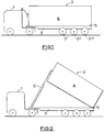
- Figure 1 is a schematic drawing showing a side elevation of a towing vehicle and a tipping trailer in transport mode,
- Figure 2 is similar to Figure 1 but shows the trailer in tipping mode,
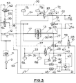
- Figure 3 is a pneumatic circuit diagram, and
- Figure 4 shows a modification to the circuit diagram of Figure 3.
- Referring to Figures 1 and 2 of the drawings, a
tractor vehicle 1 is coupled to a tippingtrailer 2 through a conventional fifth wheel coupling, not shown. Thetrailer 2 has achassis 3, abody 4 pivoted to the chassis at apivot 5 and atelescopic jack 6, for example an hydraulic jack, pivotally connected between thechassis 3 and thebody 4. The trailer has three axles, being a leading axle 7', a middle axle 7'' and a rear axle 7''', towards its rear and an air suspension system of known construction is connected between each axle and thechassis 3 so that the axles are carried by pivotally mounted trailing arms, not shown, with an adjacent air spring acting generally between each end of each axle and the chassis. - As is seen in Figure 1, the
body 4 rests on thechassis 3 so that its load is, distributed along the length of the chassis. Turning now to Figure 2, thejack 6 has been extended, lifting the front of thebody 4 away from thechassis 3. The weight of the body (and its load) is now reacted between the ends of thechassis 3, giving rise to a hogging bending moment on the chassis. It will also be seen that the leading and middle axles 7', 7'' are located a significant distance forward of thepivot 5 and so the air springs for these axles have a significant lever arm through which they apply a further hogging moment to thechassis 3. The pressure in these air springs will be substantially the same as the pressure in the air springs of the rear axle 7''' so that the upward loads they exert on thechassis 3 will be substantially the same, but applied through lever arms of increasing length from rear to front. - Referring now to Figure 3, first air springs -that is to say the air springs at one side of the trailer for the axles 7', 7'', 7''' - are referenced 7A, 7B, 7C from front to rear of the trailer. Second air springs at the other side of the trailer for the axles are referenced 8A, 8B, 8C. Thus, the leading axle 7' has
air springs 7A, 8A, the middle axle 7'' hasair springs 7B, 8B and the rear axle 7''' hasair springs 7C, 8C. - The conventional trailer air system includes a filter 9, brake
pressure protection valve 11,air reservoir 12,suspension levelling valve 13 and associated connecting pipes for connecting these components together and to a compressor, not shown, on the tractor vehicle. - As illustrated the air suspension system includes a dump system comprising pilot operated two-position
spring return valves 14, 15 (constituting fourth and fifth selectively operable valve means) and a two-position manually operated pilot return dump valve 16 (constituting sixth valve means, foroperating valves 14, 15), shown in the "Dump" selection in which the pilots ofvalves valves Dump valve 16 is reverted by air pressure at its pilot from apipe 65 which is pressurised when the vehicle service brake is applied. Alternatively, it could be reverted by other means, for example solenoid operation actuated from the brake-light circuit. - The levelling
valve 13 receives a pressure air supply via thereservoir 12 and apipe 17. Valve 13 is connected to air spring 7C via apipe 18,valve 14 andpipes pipes -
Levelling valve 13 is also connected toair spring 8C viapipes valve 15 andpipes air springs pipe 31, avalve 32 andpipes - The valves 23, 32 (constituting, respectively, first and second selectively operable valve means) are two-position pilot operated spring return valves, and their pilots are connected by
pipes - A pilot operated
pressure reducing valve 41 receives a pressure air supply via thelevelling valve 13,pipes valve 15,pipe 28 and apipe 42. Its pilot is connected topipe 42 by apipe 43. The downstream side ofvalve 41 is connected to valve 23 viapipes 44, 45 a two-way restrictor 46 and apipe 47. Similarly,valve 41 is connected tovalve 32 viapipes way restrictor 49 andpipe 51. - A two-position pilot operated spring return valve 52 (constituting interlock means) receives a pressure air supply from
reservoir 12 viapipe 53 and this also suppliesvalve 39 viapipe 54. Apipe 55 connectsvalve 52 to the pilot ofvalve 39. - A
pipe 56 connectsreservoir 12 tovalve 16 to supply pressure air throughvalve 16 to the pilots ofvalves pipes - Input to a load sensing valve (for modulating brake air pressure dependent on the vehicle load) is provided by a
pipe 61 connected topipe 19 and by apipe 62, also by a pipe 63 connected topipe 26 and by apipe 64. - Assuming that the vehicle service brake is applied, air pressure in
pipe 65 causes reversion of valve 16 (reversion will in fact be the normal mode for this valve). Pressure fromreservoir 12 passes throughpipe 56,valve 16,pipes valves levelling valve 13 and the pilot ofvalve 39 is connected to atmosphere. - If
valve 39 is now operated pressure air fromreservoir 12 passes throughpipes valve 39 andpipes valves 23, 32 causing these valves to change over. Theair springs air springs 7C, 8C at the rear axle 7''' and are connected bypipes restrictors pipes pressure reducing valve 41. The latter is operated by its pilot fed with pressure air throughpipe 43, and controls the pressure in theair springs pressure reducing valve 41 preferably has a facility for setting the output pressure, so that it may be adjusted. The reduced pressure output required will depend on the configuration of the vehicle and its axles, its construction and loading. Preferably the lower pressure is set to be between 50% and 70% of the pressure of the air springs of the rear axle. In the example of the tri-axle tipper trailer which has been described the reduced pressure output may be of the order of 60% of the input pressure. That is to say, the air springs 7C, 8C of the rear axle 7''' will be at 100% of the pressure downstream of levellingvalve 13 and the air springs 7A, 8A; 7B, 8B of the front and middle axles 7', 7'' will be at 60% of that pressure, thus reducing the hogging moment applied to the chassis via the air suspension as compared with the situation when all the air springs are at the same pressure. - Clearly, if
valves 23, 32 are located alternatively between air springs 7A, 7B and 8A, 8B then the reduced pressure will be supplied to the air springs 7A, 8A of the front axle 7' and full pressure will be supplied to the air springs 7B, 7C and 8B, 8C at the middle and rear axles 7'', 7'''. - The
restrictors valve 13. - The
valve 39 is reset manually to revert the air suspension system to the normal transport mode following completion of load discharge. - It will be seen that
valve 39 cannot be operated to effect load re-distribution between the axles ifdump valve 16 is in the "Dump" selection because theinterlock valve 52 causes pressurisation of the pilot ofvalve 39. - If a dump system is not fitted the
valves interlock valve 52. In consequence a two-position manually operated valve can be substituted for the manually operated pilotoverride return valve 39. - It may be desirable to provide for an automatic reversion of the air suspension system to the normal transport mode following completion of load discharge, in case the operator fails to reset
valve 39 manually. - Referring now to Figure 4 of the drawings, the hydraulic system for tipping the body of the vehicle to discharge the load is represented by a
pipe 71 through which apump 72 draws hydraulic fluid from a reservoir (not shown) and discharges it through apipe 73 to aselector valve 74. Fromselector valve 74 fluid can be supplied through apipe 75 to thehydraulic jack 6. Apipe 76 connectspipe 75 to a two-position pilot operated spring return valve 77 (seventh valve means) inserted inpipe 38 of Figure 3. - When the
selector valve 74 is selected to cause extension of thejack 6 the hydraulic pressure generatedcauses valve 77 to change over. Operation of manually operatedvalve 39 will cause reduction of the air pressure in the air springs 7A, 8A and 7B, 8B as has been described. - On completion of load discharge the
selector valve 74 is operated to return thebody 4 so that it rests on thechassis 3. The hydraulic pressure inpipes decays allowing valve 77 to revert whereby the pilots ofvalves 23, 32 are connected to atmosphere.Valves 23, 32 revert and the air suspension reverts to the normal transport mode even though thevalve 39 has not been reset manually. - It will be appreciated that the
valve 77, instead of being pilot operated direct from the hydraulic system, could be solenoid operated with the signal being derived from a pressure operated switch at thejack 6 or inpipe 75. - If wholly automatic operation is required so that the pressure in the air springs 7A, 8A and 7B, 8B is automatically reduced when body tipping is selected, this may be effected by omitting the
valve 39 so that valve 77 (or its solenoid operated replacement) is supplied with pressure air frompipe 54. As the body is reverted so will the air suspension revert to the normal transport mode as already described. - It will also be appreciated that the
valve 77, instead of having pilot operation, could be mechanically actuated by movement of the body during tipping. - Again, the
valve 39 has been described as manually operated but this could be replaced by a solenoid valve, for example remote operated from the vehicle cab. - The
restrictors 46, 49 (and corresponding restrictors in valve 13) have been described as being two-way restrictors, that is, flow is restricted in both directions. It may be advantageous in certain applications for these to be one-way restrictors so as only to restrict flow to the air springs and not from the air springs.
Claims (11)
- A vehicle having a chassis, first and second axles (7'''; 7'', 7') mounted towards the rear of the vehicle and a multi-axle air suspension system comprising for each of said axles (7'''; 7'', 7') a first air spring (7C, 7B, 7A) and a second air spring (8C, 8B, 8A) each adapted to be mounted to act between a chassis of the vehicle and a respective end of the axle (7'''; 7'', 7'), first and second interconnecting means (18, 14, 19, 21, 24, 25 and 26, 27, 15, 28, 29, 31, 33, 34, 35) pneumatically interconnecting the first air springs (7C, 7B, 7A) and the second air springs (8C, 8B, 8A) respectively, and suspension levelling valve means (13) pneumatically connected between a source of pressure air (12) and the first and second air springs and being adapted to be connected mechanically between an axle (7'''; 7'', 7') and the chassis of the vehicle for operation, the suspension system also being provided with first and second valve means (23; 32) in pneumatic circuit with the first and second air springs (7C, 7B, 7A; 8C, 8B, 8A) respectively of each of the said axles (7'''; 7'', 7'), and pressure reducing valve means (41) in pneumatic circuit with a source of pressure air and with the first and second valve means (23; 32), the arrangement being such that operation of the first and second valve means (23; 32) causes the air springs (7C, 8C) of the first axle (7''') to be isolated from the air springs (7B, 8B; 7A, 8A) of the second axle and connects the pressure reducing valve means (41) to the air springs (7B, 8B; 7A, 8A) of said second axle whereby the air pressure in the air springs of said second axle is controlled at a lower pressure than in the air springs (7C, 8C) of the first axle (7'''), characterised in that a body is pivoted to the rear end of the chassis, actuator means is pivotally connected between the chassis and body for lifting the front of the body away from the chassis for tipping, the second axle is forward of the first axle, and third valve means is provided to operate the first and second valve means when the body is in the tipped position.
- A vehicle as claimed in Claim 1 characterised in that restriction means (46, 49) are provided in circuit between the pressure reducing valve means (41) and the first and second valve means (23; 32).
- A vehicle as claimed in Claim 1 or Claim 2 characterised in that the pressure reducing valve means (41) is pilot operated.
- A vehicle as claimed in any one of Claims 1 to 3 characterised in that the pressure reducing valve means (41) is adjustable to facilitate setting of said lower pressure to a desired value.
- A vehicle as claimed in any preceding Claim characterised in that said lower pressure is set to be between 50% and 70% of the pressure obtaining in the air springs (7C, 8C) of at least the first axle (7''').
- A vehicle as claimed in any preceding claim characterised in that the suspension system includes dump means (14, 15, 16) for releasing pressure air from the air springs (7C, 8C,; 7B, 8B; 7A, 8A), and interlock valve means (52) in circuit with the dump means (14, 15, 16) whereby operation of the dump means to release pressure air from the air springs causes the interlock valve means (52) to prevent operation of the third valve means (39), thereby preventing operation of the first and second valve means (23; 32) to isolate the air springs (7C, 8C) of at least the first axle (7''') from the other air springs (7B, 8B; 7A, 8A).
- A vehicle as claimed in Claim 6 characterised in that the dump means comprises fourth and fifth valve means (14; 15) which are pilot operated and in circuit between the levelling valve means (13) and the first and second air springs (7C, 7B, 7A; 8C, 8B, 8A) respectively, and a sixth valve means (16) in circuit with a pressure air supply and operable to connect the air supply to the pilots of the fourth and fifth valve means (14; 15) to operate them and so connect the respective air springs to atmosphere.
- A vehicle as claimed in Claim 7 characterised in that the third valve means (39) and the interlock valve means (52) are pilot operated and the sixth valve means (16), on operation, also connects the air supply to the pilot of the interlock valve means (52) causing operation thereof, whereby a pressure air supply to the interlock valve means (52) is connected to the pilot of the third valve means (39) rendering the third valve means inoperable to isolate at least the air springs (7C, 8C) of the first axle (7''') from the other air springs (7B, 8B; 7A, 8A).
- A vehicle as claimed in any preceding Claim characterised in that the first and second valve means (23; 32) are two-position three way pilot operated spring return valves.
- A vehicle as claimed in any preceding Claim characterised in that the suspension system includes in circuit with the third valve means (39) a seventh valve means (77) having a first condition in which it isolates the third valve means (39) from the first and second valve means (23; 32) and a second condition in which it connects the third valve means (39) to the first and second valve means (23; 32), the seventh valve means (77) being operable to the second condition in response to commencement of operation of the actuator means to tip the body.
- A vehicle as claimed in Claim 10 characterised in that the actuator means comprises a tipping jack having a pressure hydraulic system and the seventh valve means (77) comprises a two-position pilot operated spring return valve, the pilot thereof being connected to the pressure hydraulic system of the tipping jack.
Applications Claiming Priority (2)
| Application Number | Priority Date | Filing Date | Title |
|---|---|---|---|
| GB8929185 | 1989-12-23 | ||
| GB898929185A GB8929185D0 (en) | 1989-12-23 | 1989-12-23 | Load distribution on air suspended vehicles |
Publications (3)
| Publication Number | Publication Date |
|---|---|
| EP0435587A2 EP0435587A2 (en) | 1991-07-03 |
| EP0435587A3 EP0435587A3 (en) | 1992-07-08 |
| EP0435587B1 true EP0435587B1 (en) | 1996-04-03 |
Family
ID=10668508
Family Applications (1)
| Application Number | Title | Priority Date | Filing Date |
|---|---|---|---|
| EP19900314050 Expired - Lifetime EP0435587B1 (en) | 1989-12-23 | 1990-12-20 | Multi-axle air suspension system for a vehicle |
Country Status (10)
| Country | Link |
|---|---|
| EP (1) | EP0435587B1 (en) |
| AU (1) | AU646005B2 (en) |
| DE (1) | DE69026359T2 (en) |
| DK (1) | DK0435587T3 (en) |
| ES (1) | ES2085338T3 (en) |
| GB (2) | GB8929185D0 (en) |
| IE (1) | IE64665B1 (en) |
| NZ (1) | NZ236519A (en) |
| PT (1) | PT96354B (en) |
| ZA (1) | ZA9010241B (en) |
Families Citing this family (8)
| Publication number | Priority date | Publication date | Assignee | Title |
|---|---|---|---|---|
| GB2337731B (en) * | 1998-05-27 | 2000-04-05 | Overlander Trailers Ltd | Semi-trailer assembly |
| ES2159453B1 (en) * | 1998-06-08 | 2002-04-01 | Accesorios Y Elevadores Valenc | VEHICLE SUSPENSION CONTROL MECHANISM. |
| GB2356607B (en) * | 1999-11-29 | 2002-01-23 | Sdc Trailers Ltd | Semi-trailer assembly |
| FR2945477A1 (en) * | 2009-05-18 | 2010-11-19 | Claude Jean Desvigne | Attitude correcting device for suspension of road vehicle, has suspension suspended by inflatable elastic cushions, and leveling and rapid discharge valves whose relations are isolated when leveling valve is in position |
| CN102407748B (en) * | 2011-10-12 | 2016-03-02 | 中通客车控股股份有限公司 | A kind of shaft load control system of support shaft |
| DE102014108557A1 (en) * | 2014-06-18 | 2015-12-24 | Knorr-Bremse Systeme für Nutzfahrzeuge GmbH | Air suspension device for lifting and lowering a vehicle body |
| DE102014108556B4 (en) * | 2014-06-18 | 2021-04-22 | Knorr-Bremse Systeme für Nutzfahrzeuge GmbH | Air suspension device for raising and lowering a vehicle body |
| US10137750B2 (en) | 2016-02-25 | 2018-11-27 | Bendix Commercial Vehicle Systems Llc | Controller and method for controlling a lift axle and air suspension on a trailer |
Family Cites Families (4)
| Publication number | Priority date | Publication date | Assignee | Title |
|---|---|---|---|---|
| FR1232078A (en) * | 1958-11-24 | 1960-10-05 | Magneti Marelli Spa | Automatic pneumatic distributor for air suspension systems, in particular for three-axle vehicles |
| DE3545222A1 (en) * | 1985-12-20 | 1987-06-25 | Bosch Gmbh Robert | Starting aid for motor vehicles with air suspension |
| DE3638849A1 (en) * | 1986-11-13 | 1988-05-19 | Bosch Gmbh Robert | Air suspension for vehicle with double axle |
| IT1224010B (en) * | 1988-12-20 | 1990-09-26 | Viberti Spa Off | HEIGHT ADJUSTMENT DEVICE COMPARED TO THE GROUND OF A ROAD VEHICLE FRAME EQUIPPED WITH A LIFTING AXLE |
-
1989
- 1989-12-23 GB GB898929185A patent/GB8929185D0/en active Pending
-
1990
- 1990-12-14 IE IE453090A patent/IE64665B1/en not_active IP Right Cessation
- 1990-12-18 NZ NZ23651990A patent/NZ236519A/en unknown
- 1990-12-19 AU AU68296/90A patent/AU646005B2/en not_active Ceased
- 1990-12-19 GB GB9027504A patent/GB2239222B/en not_active Expired - Fee Related
- 1990-12-19 ZA ZA9010241A patent/ZA9010241B/en unknown
- 1990-12-20 DK DK90314050T patent/DK0435587T3/en active
- 1990-12-20 ES ES90314050T patent/ES2085338T3/en not_active Expired - Lifetime
- 1990-12-20 EP EP19900314050 patent/EP0435587B1/en not_active Expired - Lifetime
- 1990-12-20 DE DE1990626359 patent/DE69026359T2/en not_active Expired - Fee Related
- 1990-12-21 PT PT9635490A patent/PT96354B/en not_active IP Right Cessation
Also Published As
| Publication number | Publication date |
|---|---|
| EP0435587A3 (en) | 1992-07-08 |
| DK0435587T3 (en) | 1996-05-06 |
| DE69026359D1 (en) | 1996-05-09 |
| AU6829690A (en) | 1991-06-27 |
| NZ236519A (en) | 1992-05-26 |
| GB8929185D0 (en) | 1990-02-28 |
| GB9027504D0 (en) | 1991-02-06 |
| EP0435587A2 (en) | 1991-07-03 |
| IE904530A1 (en) | 1991-07-03 |
| ES2085338T3 (en) | 1996-06-01 |
| PT96354B (en) | 1998-07-31 |
| IE64665B1 (en) | 1995-08-23 |
| PT96354A (en) | 1992-08-31 |
| AU646005B2 (en) | 1994-02-03 |
| GB2239222B (en) | 1993-08-25 |
| GB2239222A (en) | 1991-06-26 |
| ZA9010241B (en) | 1991-10-30 |
| DE69026359T2 (en) | 1996-09-05 |
Similar Documents
| Publication | Publication Date | Title |
|---|---|---|
| US4483409A (en) | Integral hydraulic tilt-cab suspension and tilting apparatus | |
| AU737752B2 (en) | Self-steering, caster adjustable suspension system | |
| US4993729A (en) | Vehicle suspension | |
| US10350954B2 (en) | Transport trailer load balancing suspension and steering systems | |
| EP0435587B1 (en) | Multi-axle air suspension system for a vehicle | |
| US4588201A (en) | Hydraulic system for an auxiliary load transfer device | |
| US6921097B2 (en) | Arrangement for wheel suspension | |
| US11643141B2 (en) | Trailer assembly and associated self-erecting crane | |
| EP1203676A1 (en) | Method for variation of the load distribution on driving wheels of operating vehicles and device that carries out this method | |
| GB2184405A (en) | Trailers | |
| US3066983A (en) | Coupling and dumping system | |
| WO1998030404A1 (en) | Tandem rear axle suspensions for trucks and truck-tractors | |
| US11712938B1 (en) | Pistonless pneumatic dampening and straight centering for a steerable axle of a heavy-duty vehicle | |
| AU2006202768B2 (en) | Transport vehicles | |
| CA2304897C (en) | Axle booster | |
| GB2223463A (en) | Fluid suspension for a trailer | |
| GB2222120A (en) | Controlling the loading of a non-driven axle in a multi-axle vehicle | |
| AU2013201290B2 (en) | Improvements to haul bodies | |
| AU751204B3 (en) | Transport vehicles | |
| SU1156928A1 (en) | Tractor-drawn carriage for hauling loads on slopes | |
| GB2372490A (en) | Weight transfer system for articulated vehicles | |
| JPS61263819A (en) | Level-control device for vehicles | |
| AU2614602A (en) | Transport vehicles | |
| MXPA99001049A (en) | Adjustable suspension system, inclination forward auto-goberna |
Legal Events
| Date | Code | Title | Description |
|---|---|---|---|
| PUAI | Public reference made under article 153(3) epc to a published international application that has entered the european phase |
Free format text: ORIGINAL CODE: 0009012 |
|
| AK | Designated contracting states |
Kind code of ref document: A2 Designated state(s): BE DE DK ES FR IT NL |
|
| PUAL | Search report despatched |
Free format text: ORIGINAL CODE: 0009013 |
|
| AK | Designated contracting states |
Kind code of ref document: A3 Designated state(s): BE DE DK ES FR IT NL |
|
| 17P | Request for examination filed |
Effective date: 19921029 |
|
| 17Q | First examination report despatched |
Effective date: 19940727 |
|
| RAP1 | Party data changed (applicant data changed or rights of an application transferred) |
Owner name: ROR ROCKWELL LIMITED |
|
| GRAH | Despatch of communication of intention to grant a patent |
Free format text: ORIGINAL CODE: EPIDOS IGRA |
|
| GRAA | (expected) grant |
Free format text: ORIGINAL CODE: 0009210 |
|
| AK | Designated contracting states |
Kind code of ref document: B1 Designated state(s): BE DE DK ES FR IT NL |
|
| REG | Reference to a national code |
Ref country code: DK Ref legal event code: T3 |
|
| REF | Corresponds to: |
Ref document number: 69026359 Country of ref document: DE Date of ref document: 19960509 |
|
| ET | Fr: translation filed | ||
| REG | Reference to a national code |
Ref country code: ES Ref legal event code: FG2A Ref document number: 2085338 Country of ref document: ES Kind code of ref document: T3 |
|
| ITF | It: translation for a ep patent filed |
Owner name: ING. A. GIAMBROCONO & C. S.R.L. |
|
| PLBE | No opposition filed within time limit |
Free format text: ORIGINAL CODE: 0009261 |
|
| STAA | Information on the status of an ep patent application or granted ep patent |
Free format text: STATUS: NO OPPOSITION FILED WITHIN TIME LIMIT |
|
| 26N | No opposition filed | ||
| PGFP | Annual fee paid to national office [announced via postgrant information from national office to epo] |
Ref country code: DK Payment date: 19981117 Year of fee payment: 9 |
|
| PGFP | Annual fee paid to national office [announced via postgrant information from national office to epo] |
Ref country code: BE Payment date: 19981124 Year of fee payment: 9 |
|
| PGFP | Annual fee paid to national office [announced via postgrant information from national office to epo] |
Ref country code: FR Payment date: 19981127 Year of fee payment: 9 |
|
| PGFP | Annual fee paid to national office [announced via postgrant information from national office to epo] |
Ref country code: ES Payment date: 19981218 Year of fee payment: 9 |
|
| PGFP | Annual fee paid to national office [announced via postgrant information from national office to epo] |
Ref country code: NL Payment date: 19981231 Year of fee payment: 9 |
|
| PGFP | Annual fee paid to national office [announced via postgrant information from national office to epo] |
Ref country code: DE Payment date: 19990222 Year of fee payment: 9 |
|
| PG25 | Lapsed in a contracting state [announced via postgrant information from national office to epo] |
Ref country code: DK Free format text: LAPSE BECAUSE OF NON-PAYMENT OF DUE FEES Effective date: 19991220 |
|
| PG25 | Lapsed in a contracting state [announced via postgrant information from national office to epo] |
Ref country code: BE Free format text: LAPSE BECAUSE OF NON-PAYMENT OF DUE FEES Effective date: 19991231 |
|
| BERE | Be: lapsed |
Owner name: ROR ROCKWELL LTD Effective date: 19991231 |
|
| PG25 | Lapsed in a contracting state [announced via postgrant information from national office to epo] |
Ref country code: NL Free format text: LAPSE BECAUSE OF NON-PAYMENT OF DUE FEES Effective date: 20000701 |
|
| PG25 | Lapsed in a contracting state [announced via postgrant information from national office to epo] |
Ref country code: FR Free format text: LAPSE BECAUSE OF NON-PAYMENT OF DUE FEES Effective date: 20000831 |
|
| NLV4 | Nl: lapsed or anulled due to non-payment of the annual fee |
Effective date: 20000701 |
|
| REG | Reference to a national code |
Ref country code: DK Ref legal event code: EBP |
|
| PG25 | Lapsed in a contracting state [announced via postgrant information from national office to epo] |
Ref country code: DE Free format text: LAPSE BECAUSE OF NON-PAYMENT OF DUE FEES Effective date: 20001003 |
|
| REG | Reference to a national code |
Ref country code: FR Ref legal event code: ST |
|
| PG25 | Lapsed in a contracting state [announced via postgrant information from national office to epo] |
Ref country code: ES Free format text: LAPSE BECAUSE OF NON-PAYMENT OF DUE FEES Effective date: 20001221 |
|
| REG | Reference to a national code |
Ref country code: ES Ref legal event code: FD2A Effective date: 20010113 |
|
| PG25 | Lapsed in a contracting state [announced via postgrant information from national office to epo] |
Ref country code: IT Free format text: LAPSE BECAUSE OF NON-PAYMENT OF DUE FEES Effective date: 20051220 |