EP0435587B1 - Mehrachsluftaufhängungssystem für ein Fahrzeug - Google Patents
Mehrachsluftaufhängungssystem für ein Fahrzeug Download PDFInfo
- Publication number
- EP0435587B1 EP0435587B1 EP19900314050 EP90314050A EP0435587B1 EP 0435587 B1 EP0435587 B1 EP 0435587B1 EP 19900314050 EP19900314050 EP 19900314050 EP 90314050 A EP90314050 A EP 90314050A EP 0435587 B1 EP0435587 B1 EP 0435587B1
- Authority
- EP
- European Patent Office
- Prior art keywords
- valve means
- air
- axle
- vehicle
- air springs
- Prior art date
- Legal status (The legal status is an assumption and is not a legal conclusion. Google has not performed a legal analysis and makes no representation as to the accuracy of the status listed.)
- Expired - Lifetime
Links
- 239000000725 suspension Substances 0.000 title claims description 29
- 238000009877 rendering Methods 0.000 claims 1
- 238000010276 construction Methods 0.000 description 3
- 230000002411 adverse Effects 0.000 description 2
- 238000005452 bending Methods 0.000 description 2
- 238000010586 diagram Methods 0.000 description 2
- 239000012530 fluid Substances 0.000 description 2
- 239000012190 activator Substances 0.000 description 1
- 230000008878 coupling Effects 0.000 description 1
- 238000010168 coupling process Methods 0.000 description 1
- 238000005859 coupling reaction Methods 0.000 description 1
- 230000001419 dependent effect Effects 0.000 description 1
- 230000000694 effects Effects 0.000 description 1
- 230000005484 gravity Effects 0.000 description 1
- 230000004048 modification Effects 0.000 description 1
- 238000012986 modification Methods 0.000 description 1
Images

Classifications
-
- B—PERFORMING OPERATIONS; TRANSPORTING
- B60—VEHICLES IN GENERAL
- B60G—VEHICLE SUSPENSION ARRANGEMENTS
- B60G5/00—Resilient suspensions for a set of tandem wheels or axles having interrelated movements
-
- B—PERFORMING OPERATIONS; TRANSPORTING
- B60—VEHICLES IN GENERAL
- B60G—VEHICLE SUSPENSION ARRANGEMENTS
- B60G11/00—Resilient suspensions characterised by arrangement, location or kind of springs
- B60G11/26—Resilient suspensions characterised by arrangement, location or kind of springs having fluid springs only, e.g. hydropneumatic springs
- B60G11/27—Resilient suspensions characterised by arrangement, location or kind of springs having fluid springs only, e.g. hydropneumatic springs wherein the fluid is a gas
-
- B—PERFORMING OPERATIONS; TRANSPORTING
- B60—VEHICLES IN GENERAL
- B60G—VEHICLE SUSPENSION ARRANGEMENTS
- B60G17/00—Resilient suspensions having means for adjusting the spring or vibration-damper characteristics, for regulating the distance between a supporting surface and a sprung part of vehicle or for locking suspension during use to meet varying vehicular or surface conditions, e.g. due to speed or load
- B60G17/02—Spring characteristics, e.g. mechanical springs and mechanical adjusting means
- B60G17/04—Spring characteristics, e.g. mechanical springs and mechanical adjusting means fluid spring characteristics
- B60G17/052—Pneumatic spring characteristics
-
- B—PERFORMING OPERATIONS; TRANSPORTING
- B60—VEHICLES IN GENERAL
- B60G—VEHICLE SUSPENSION ARRANGEMENTS
- B60G2202/00—Indexing codes relating to the type of spring, damper or actuator
- B60G2202/40—Type of actuator
- B60G2202/41—Fluid actuator
- B60G2202/412—Pneumatic actuator
-
- B—PERFORMING OPERATIONS; TRANSPORTING
- B60—VEHICLES IN GENERAL
- B60G—VEHICLE SUSPENSION ARRANGEMENTS
- B60G2300/00—Indexing codes relating to the type of vehicle
- B60G2300/02—Trucks; Load vehicles
-
- B—PERFORMING OPERATIONS; TRANSPORTING
- B60—VEHICLES IN GENERAL
- B60G—VEHICLE SUSPENSION ARRANGEMENTS
- B60G2300/00—Indexing codes relating to the type of vehicle
- B60G2300/04—Trailers
-
- B—PERFORMING OPERATIONS; TRANSPORTING
- B60—VEHICLES IN GENERAL
- B60G—VEHICLE SUSPENSION ARRANGEMENTS
- B60G2800/00—Indexing codes relating to the type of movement or to the condition of the vehicle and to the end result to be achieved by the control action
- B60G2800/01—Attitude or posture control
- B60G2800/019—Inclination due to load distribution or road gradient
- B60G2800/0192—Inclination due to load distribution or road gradient longitudinal with regard to vehicle
-
- B—PERFORMING OPERATIONS; TRANSPORTING
- B60—VEHICLES IN GENERAL
- B60G—VEHICLE SUSPENSION ARRANGEMENTS
- B60G2800/00—Indexing codes relating to the type of movement or to the condition of the vehicle and to the end result to be achieved by the control action
- B60G2800/20—Stationary vehicle
Definitions
- This invention relates to a vehicle having a multi-axle air suspension system.
- the equalisation system on a conventional multi-axle mechanical spring suspension is unable, due to frictional forces and geometrical limitations, to equalise the loading between the axles and the loading condition described during tipping can even result in the wheels of the leading axle lifting clear of the ground.
- the present invention is aimed at alleviating the adverse loading condition described.
- the present invention is particularly concerned with a vehicle of the type, such as disclosed in DE-A-3545222, having a chassis, first and second axles mounted towards the rear of the vehicle and a multi-axle air suspension system comprising for each of said axles a first air spring and a second air spring each adapted to be mounted to act between a chassis of the vehicle and a respective end of the axle,first and second interconnecting means pneumatically interconnecting the first air springs and the second air springs respectively, and suspension levelling valve means pneumatically connected between a source of pressure air and the first and second air springs and being adapted to be connected mechanically between an axle and the chassis of the vehicle for operation, the suspension system also being provided with first and second valve means in pneumatic circuit with the first and second air springs respectively of each of the axles, and pressure reducing valve means in pneumatic circuit with a source of pressure air and with the first and second valve means, the arrangement being such that operation of the first and second valve means causes the air springs of the first axle to be isolated from the
- axle herein also includes a pair of aligned stub axles, for example as in an independent air suspension system, an example of which is described and illustrated in our British Patent No. 2165195.
- a vehicle is provided of the type set forth which is characterised in that a body is pivoted to the rear end of the chassis, activator means is pivotally connected between the chassis and the body for lifting the front of the body away from the chassis for tipping, the second axle is forward of the first axle, and third valve means is provided to operate the first and second valve means when the body is in the tipped position.
- the selective overiding of the normal equalisation system of the multi-axle air suspension system of the vehicle enables the second axle to be selectively loaded more lightly than the first axle when the vehicle is tipping so as to avoid adverse loading on the chassis.
- the multi-axle air suspension system may include a "dump system" to allow selective deflation of the air springs.
- the dump system may comprise fourth and fifth selectively operable valve means in pneumatic circuit between the levelling valve means and the first and second air springs respectively, and sixth valve means to operate the third and fourth valve means whereby the air springs are disconnected from the levelling valve means and are connected to atmosphere to allow deflation of the air springs.
- interlock means which is operable when the fourth and fifth valve means are operated for deflation of the air springs so as to disable the third valve means, and so prevent operation of the first and second valve means to isolate the air springs of at least the first axle from the air springs of the second axle.
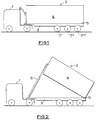
- a tractor vehicle 1 is coupled to a tipping trailer 2 through a conventional fifth wheel coupling, not shown.
- the trailer 2 has a chassis 3, a body 4 pivoted to the chassis at a pivot 5 and a telescopic jack 6, for example an hydraulic jack, pivotally connected between the chassis 3 and the body 4.
- the trailer has three axles, being a leading axle 7', a middle axle 7'' and a rear axle 7'', towards its rear and an air suspension system of known construction is connected between each axle and the chassis 3 so that the axles are carried by pivotally mounted trailing arms, not shown, with an adjacent air spring acting generally between each end of each axle and the chassis.
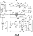
- first air springs -that is to say the air springs at one side of the trailer for the axles 7', 7'', 7''' - are referenced 7A, 7B, 7C from front to rear of the trailer.
- Second air springs at the other side of the trailer for the axles are referenced 8A, 8B, 8C.
- the leading axle 7' has air springs 7A, 8A
- the middle axle 7'' has air springs 7B, 8B
- the rear axle 7'''' has air springs 7C, 8C.
- the conventional trailer air system includes a filter 9, brake pressure protection valve 11, air reservoir 12, suspension levelling valve 13 and associated connecting pipes for connecting these components together and to a compressor, not shown, on the tractor vehicle.
- the air suspension system includes a dump system comprising pilot operated two-position spring return valves 14, 15 (constituting fourth and fifth selectively operable valve means) and a two-position manually operated pilot return dump valve 16 (constituting sixth valve means, for operating valves 14, 15), shown in the "Dump" selection in which the pilots of valves 14, 15 are connected to atmosphere and the air springs are also connected to atmosphere via the valves 14, 15.
- Dump valve 16 is reverted by air pressure at its pilot from a pipe 65 which is pressurised when the vehicle service brake is applied. Alternatively, it could be reverted by other means, for example solenoid operation actuated from the brake-light circuit.
- the levelling valve 13 receives a pressure air supply via the reservoir 12 and a pipe 17.
- Valve 13 is connected to air spring 7C via a pipe 18, valve 14 and pipes 19, 21, and on to air springs 7A, 7B via pipe 22, a valve 23 and pipes 24, 25.
- Levelling valve 13 is also connected to air spring 8C via pipes 26, 27, valve 15 and pipes 28, 29, and on to air springs 8A, 8B via pipe 31, a valve 32 and pipes 33, 34 and 35.
- valves 23, 32 are two-position pilot operated spring return valves, and their pilots are connected by pipes 36, 37, 38 to a two position manually operated valve 39 (constituting third valve means, for operating valves 23, 32) having an override pilot operated return.
- a pilot operated pressure reducing valve 41 receives a pressure air supply via the levelling valve 13, pipes 26, 27, valve 15, pipe 28 and a pipe 42. Its pilot is connected to pipe 42 by a pipe 43. The downstream side of valve 41 is connected to valve 23 via pipes 44, 45 a two-way restrictor 46 and a pipe 47. Similarly, valve 41 is connected to valve 32 via pipes 44, 48, two-way restrictor 49 and pipe 51.
- a two-position pilot operated spring return valve 52 receives a pressure air supply from reservoir 12 via pipe 53 and this also supplies valve 39 via pipe 54.
- a pipe 55 connects valve 52 to the pilot of valve 39.
- a pipe 56 connects reservoir 12 to valve 16 to supply pressure air through valve 16 to the pilots of valves 14, 15 and 52 via pipes 57, 58 and 59.
- Input to a load sensing valve is provided by a pipe 61 connected to pipe 19 and by a pipe 62, also by a pipe 63 connected to pipe 26 and by a pipe 64.
- valve 16 Assuming that the vehicle service brake is applied, air pressure in pipe 65 causes reversion of valve 16 (reversion will in fact be the normal mode for this valve). Pressure from reservoir 12 passes through pipe 56, valve 16, pipes 57, 58 and 59 to operate valves 15, 14, 52 respectively whereby the air springs are connected to the levelling valve 13 and the pilot of valve 39 is connected to atmosphere.
- valve 39 pressure air from reservoir 12 passes through pipes 53, 54, valve 39 and pipes 38, 36, 37 to operate the pilots of valves 23, 32 causing these valves to change over.
- the air springs 7A, 7B and 8A, 8B at the forward and middle axles 7', 7'' are now respectively isolated from the air springs 7C, 8C at the rear axle 7''' and are connected by pipes 47, 51, restrictors 46, 49 and pipes 45, 48, 44 to the downstream side of pressure reducing valve 41.
- the latter is operated by its pilot fed with pressure air through pipe 43, and controls the pressure in the air springs 7A, 7B, 8A, 8B at a reduced level.
- the pressure reducing valve 41 preferably has a facility for setting the output pressure, so that it may be adjusted.
- the reduced pressure output required will depend on the configuration of the vehicle and its axles, its construction and loading.
- the lower pressure is set to be between 50% and 70% of the pressure of the air springs of the rear axle.
- the reduced pressure output may be of the order of 60% of the input pressure.
- the air springs 7C, 8C of the rear axle 7''' will be at 100% of the pressure downstream of levelling valve 13 and the air springs 7A, 8A; 7B, 8B of the front and middle axles 7', 7'' will be at 60% of that pressure, thus reducing the hogging moment applied to the chassis via the air suspension as compared with the situation when all the air springs are at the same pressure.
- valves 23, 32 are located alternatively between air springs 7A, 7B and 8A, 8B then the reduced pressure will be supplied to the air springs 7A, 8A of the front axle 7' and full pressure will be supplied to the air springs 7B, 7C and 8B, 8C at the middle and rear axles 7'', 7'''.
- the restrictors 46, 49 are provided to give a degree of roll stiffness to the air suspension (that is, between air springs 7A, 7B and 8A, 8B) when the reduced pressure system is in operation, serving the same purpose as the restrictors shown on the downstream side of valve 13.
- the valve 39 is reset manually to revert the air suspension system to the normal transport mode following completion of load discharge.
- valve 39 cannot be operated to effect load re-distribution between the axles if dump valve 16 is in the "Dump" selection because the interlock valve 52 causes pressurisation of the pilot of valve 39.
- valves 14, 15 and 16 are omitted and there is no need for the interlock valve 52.
- a two-position manually operated valve can be substituted for the manually operated pilot override return valve 39.
- the hydraulic system for tipping the body of the vehicle to discharge the load is represented by a pipe 71 through which a pump 72 draws hydraulic fluid from a reservoir (not shown) and discharges it through a pipe 73 to a selector valve 74. From selector valve 74 fluid can be supplied through a pipe 75 to the hydraulic jack 6.
- a pipe 76 connects pipe 75 to a two-position pilot operated spring return valve 77 (seventh valve means) inserted in pipe 38 of Figure 3.
- valve 77 When the selector valve 74 is selected to cause extension of the jack 6 the hydraulic pressure generated causes valve 77 to change over. Operation of manually operated valve 39 will cause reduction of the air pressure in the air springs 7A, 8A and 7B, 8B as has been described.
- valve 74 On completion of load discharge the selector valve 74 is operated to return the body 4 so that it rests on the chassis 3.
- the hydraulic pressure in pipes 75, 76 decays allowing valve 77 to revert whereby the pilots of valves 23, 32 are connected to atmosphere.
- Valves 23, 32 revert and the air suspension reverts to the normal transport mode even though the valve 39 has not been reset manually.
- valve 77 instead of being pilot operated direct from the hydraulic system, could be solenoid operated with the signal being derived from a pressure operated switch at the jack 6 or in pipe 75.
- valve 39 If wholly automatic operation is required so that the pressure in the air springs 7A, 8A and 7B, 8B is automatically reduced when body tipping is selected, this may be effected by omitting the valve 39 so that valve 77 (or its solenoid operated replacement) is supplied with pressure air from pipe 54. As the body is reverted so will the air suspension revert to the normal transport mode as already described.
- valve 77 instead of having pilot operation, could be mechanically actuated by movement of the body during tipping.
- valve 39 has been described as manually operated but this could be replaced by a solenoid valve, for example remote operated from the vehicle cab.
- the restrictors 46, 49 (and corresponding restrictors in valve 13) have been described as being two-way restrictors, that is, flow is restricted in both directions. It may be advantageous in certain applications for these to be one-way restrictors so as only to restrict flow to the air springs and not from the air springs.
Landscapes
- Engineering & Computer Science (AREA)
- Mechanical Engineering (AREA)
- Vehicle Body Suspensions (AREA)
Claims (11)
- Ein Fahrzeug mit einem Gestell, erster und zweiter zum hinteren Ende des Fahrzeugs hin befestigten Achsen (7'''; 7'', 7') und einem Mehrachsluftaufhängungssystem, das für jede der Achsen (7'''; 7'', 7') eine erste Luftfeder (7C, 7B, 7A) und eine zweite Luftfeder (8C, 8B, 8A), von denen jede befestigt werden kann, um zwischen dem Gestell des Fahrzeugs und einem jeweiligen Ende der Achse (7'''; 7'', 7') zu wirken, eine erste und zweite Verbindungseinrichtung (18, 14, 19, 21, 24, 25 und 26, 27, 15, 28, 29, 31, 33, 34, 35), die die ersten Luftfedern (7C, 7B, 7A) bzw. die zweiten Luftfedern (8C, 8B, 8A) miteinander pneumatisch verbinden, und eine Aufhängungsnivelliervngsventileinrichtung (13) enthält, die zwischen einer Druckluftquelle (12) und den ersten und zweiten Luftfedern pneumatisch verbunden ist und die zum Betrieb mechanisch zwischen einer Achse (7'''; 7'', 7') und dem Gestell des Fahrzeugs verbunden werden kann, wobei das Aufhängungssystem auch ausgestattet ist mit einer ersten und zweiten Ventileinrichtung (23; 32) in pneumatischer Schaltung mit den ersten bzw. den zweiten Luftfedem (7C, 7B, 7A; 8C, 8B, 8A) von jede der genannten Achsen (7'''; 7'', 7') und einer Druckminderungsventileinrichtung (41) in pneumatischer Schaltung mit einer Druckluftquelle und mit der ersten und zweiten Ventileinrichtung (23; 32), wobei die Anordnung so gestaltet ist, daß eine Betätigung der ersten und zweiten Ventileinrichtung (23; 32) zur Folge hat, daß die Luftfedern (7C, 8C) der ersten Achse (7''') von den Luftfedern (7B, 8B; 7A, 8A) der zweiten Achse abgetrennt werden und die Druckminderungsventileinrichtung (41) mit den Luftfedern (7B, 8B; 7A, 8A) der zweiten Achse verbunden wird, wodurch der Luftdruck in den Luftfedern der zweiten Achse auf einen niedrigeren Luftdruck eingestellt wird als dem in den Luftfedern (7C, 8C) der ersten Achse (7'''),
dadurch gekennzeichnet,
daß ein Aufbau zum hinteren Ende des Gestells hin geschwenkt wird, eine Betätigungseinrichtungmit dem Gestell und dem Aufbau zum Anheben des vorderen Teil des Aufbaus weg vom Gestell zwecks Kippung schwenkbar verbunden ist, sich die zweite Achse vor der ersten Achse befindet und ein dritte Ventileinrichtung vorgesehen ist, um die erste und zweite Ventileinrichtung zu betätigen, wenn sich der Aufbau in der gekippten Stellung befindet. - Ein Fahrzeug gemäß Anspruch 1,
gekennzeichnet dadurch,
daß Durchflußbegrenzungseinrichtungen (46, 49) zwischen der Druckminderungsventileinrichtung (41) und der ersten und zweiten Ventileinrichtung (23; 32) in Schaltung vorgesehen sind. - Ein Fahrzeug gemäß Anspruch 1 oder Anspruch 2,
gekennzeichnet dadurch,
daß die Druckminderungsventileinrichtung (41) vorgesteuert ist. - Ein Fahrzeug gemäß irgendeinem der Ansprüche 1 bis 3,
gekennzeichnet dadurch,
daß die Druckminderungsventileinrichtung (41) verstellbar ist, um ein Einstellen des niedrigeren Drucks auf einen gewünschten Wert zu ermöglichen. - Ein Fahrzeug gemäß irgendeinem vorangehenden Anspruch,
gekennzeichnet dadurch,
daß der niedrigere Druck auf zwischen 50 % und 70 % des Drucks eingestellt wird, den man in den Luftfedern (7C, 8C) zumindest ersten Achse (7''') erreicht. - Ein Fahrzeug gemäß irgendeinem vorangehenden Anspruch,
gekennzeichnet dadurch,
daß das Aufhängungssystem eine Druckablaßeinrichtung (14, 15, 16) zur Freisetzung von Druckluft aus den Luftfedern (7C, 8C; 7B, 8B; 7A, 8A) und eine Sperrventileinrichtung (52) in Schaltung mit der Druckablaßeinrichtung (14, 15, 16) enthält, wobei eine Betätigung der Druckablaßeinrichtung zur Freisetzung von Druckluft aus den Luftfedern die Sperrventileinrichtung (52) veranlaßt, eine Betätigung der dritten Ventileinrichtung (39) zu verhindern, wodurch eine Betätigung der ersten und zweiten Ventileinrichtung (23; 32) unterbindet, um die Luftfedern (7C, 8C) zumindest der ersten Achse (7''') von den anderen Luftfedern (7B, 8B; 7A, 8A) abzutrennen. - Ein Fahrzeug gemäß Anspruch 6,
gekennzeichnet dadurch,
daß die Druckablaßeinrichtung eine vierte und fünfte Ventileinrichtung (14; 15), welche vorgesteuert sind und sich in Schaltung zwischen der Nivellierungsventileinrichtung (13) und den ersten bzw. zweiten Luftfedern (7C, 7B, 7A; 8C, 8B, 8A) befinden, und eine sechste Ventileinrichtung (16) umfaßt, die in Schaltung mit einer Druckluftversorgung ist und betätigbar ist, um die Druckversorgung mit den Steuerungen der vierten und fünften Ventileinrichtung (14; 15) zu verbinden, damit sie diese betätigen und so die jeweiligen Luftfedern mit der Umgebung verbinden. - Ein Fahrzeug gemäß Anspruch 7,
gekennzeichnet dadurch,
daß die dritte Ventileinrichtung (39) und die Sperrventileinrichtung (52) vorgesteuert sind und die sechste Ventilvorrichtung (16) bei Betätigung auch die Luftversorgung mit der Ansteuerung der Sperrventileinrichtung (52) verbindet, was deren Betätigung verursacht, wodurch eine Druckluftversorgung über die Sperrventileinrichtung (52) mit der Ansteuerung der dritten Ventileinrichtung (39) verbunden wird, was die dritte Ventileinrichtung betätigungsunfähig macht, um die Luftfedern (7C, 8C) zumindest der ersten Achse (7''') von den anderen Luftfedern (7B, 8B; 7A, 8A) abzutrennen. - Ein Fahrzeug gemäß irgendeinem vorangehenden Anspruch,
gekennzeichnet dadurch,
daß die erste und zweite Ventileinrichtung (23; 32) vorgesteuerte Zweistellungs-Dreiwege-Federrückstellventile sind. - Ein Fahrzeug gemäß irgendeinem vorangehenden Anspruch,
gekennzeichnet dadurch,
daß das Aufhängungssystem in Schaltung mit der dritten Ventileinrichtung (39) eine siebte Ventileinrichtung (77) enthält, welche einen ersten Zustand, in welchem sie die dritte Ventileinrichtung (39) von der ersten und zweiten Ventileinrichtung (23; 32) trennt, und einen zweiten Zustand besitzt, in welchem sie die dritte Ventileinrichtung (39) mit der ersten und zweiten Ventileinrichtung (23; 32) verbindet, wobei die siebte Ventileinrichtung (77) als Antwort auf die Inbetriebnahme der Betätigungseinrichtung zur Kippung des Aufbaus in den zweiten Zustand versetzt wird. - Ein Fahrzeug gemäß Anspruch 10,
gekennzeichnet dadurch,
daß die Betätigungseinrichtung einen Kippheber mit einem hydraulischen Drucksystem umfaßt und die siebte Ventileinrichtung (77) eine vorgesteuerte Zweistellungsfederrückstellventileinrichtung enthält, deren Ansteuerung mit dem hydraulischen Drucksystem des Kipphebers verbunden ist.
Applications Claiming Priority (2)
| Application Number | Priority Date | Filing Date | Title |
|---|---|---|---|
| GB898929185A GB8929185D0 (en) | 1989-12-23 | 1989-12-23 | Load distribution on air suspended vehicles |
| GB8929185 | 1989-12-23 |
Publications (3)
| Publication Number | Publication Date |
|---|---|
| EP0435587A2 EP0435587A2 (de) | 1991-07-03 |
| EP0435587A3 EP0435587A3 (en) | 1992-07-08 |
| EP0435587B1 true EP0435587B1 (de) | 1996-04-03 |
Family
ID=10668508
Family Applications (1)
| Application Number | Title | Priority Date | Filing Date |
|---|---|---|---|
| EP19900314050 Expired - Lifetime EP0435587B1 (de) | 1989-12-23 | 1990-12-20 | Mehrachsluftaufhängungssystem für ein Fahrzeug |
Country Status (10)
| Country | Link |
|---|---|
| EP (1) | EP0435587B1 (de) |
| AU (1) | AU646005B2 (de) |
| DE (1) | DE69026359T2 (de) |
| DK (1) | DK0435587T3 (de) |
| ES (1) | ES2085338T3 (de) |
| GB (2) | GB8929185D0 (de) |
| IE (1) | IE64665B1 (de) |
| NZ (1) | NZ236519A (de) |
| PT (1) | PT96354B (de) |
| ZA (1) | ZA9010241B (de) |
Families Citing this family (8)
| Publication number | Priority date | Publication date | Assignee | Title |
|---|---|---|---|---|
| GB2337731B (en) * | 1998-05-27 | 2000-04-05 | Overlander Trailers Ltd | Semi-trailer assembly |
| ES2159453B1 (es) * | 1998-06-08 | 2002-04-01 | Accesorios Y Elevadores Valenc | Mecanismo de control de suspension de vehiculos. |
| GB2356607B (en) * | 1999-11-29 | 2002-01-23 | Sdc Trailers Ltd | Semi-trailer assembly |
| FR2945477A1 (fr) * | 2009-05-18 | 2010-11-19 | Claude Jean Desvigne | Dispositif d'amelioration de stabilite et d'appuis des roues au sol pour vehicules routiers a suspension par coussins elastiques gonflables. |
| CN102407748B (zh) * | 2011-10-12 | 2016-03-02 | 中通客车控股股份有限公司 | 一种支撑轴轴荷控制系统 |
| DE102014108557A1 (de) * | 2014-06-18 | 2015-12-24 | Knorr-Bremse Systeme für Nutzfahrzeuge GmbH | Luftfederungseinrichtung zum Heben und Senken eines Fahrzeugaufbaus |
| DE102014108556B4 (de) * | 2014-06-18 | 2021-04-22 | Knorr-Bremse Systeme für Nutzfahrzeuge GmbH | Luftfederungseinrichtung zum Heben und Senken eines Fahrzeugaufbaus |
| US10137750B2 (en) | 2016-02-25 | 2018-11-27 | Bendix Commercial Vehicle Systems Llc | Controller and method for controlling a lift axle and air suspension on a trailer |
Family Cites Families (4)
| Publication number | Priority date | Publication date | Assignee | Title |
|---|---|---|---|---|
| FR1232078A (fr) * | 1958-11-24 | 1960-10-05 | Magneti Marelli Spa | Distributeur pneumatique automatique pour installations de suspensions pneumatiques en particulier pour véhicules à trois essieux |
| DE3545222A1 (de) * | 1985-12-20 | 1987-06-25 | Bosch Gmbh Robert | Anfahrhilfe fuer luftgefederte kraftfahrzeuge |
| DE3638849A1 (de) * | 1986-11-13 | 1988-05-19 | Bosch Gmbh Robert | Luftfederung fuer fahrzeug mit doppelachse |
| IT1224010B (it) * | 1988-12-20 | 1990-09-26 | Viberti Spa Off | Dispositivo per la regolazione dell'altezza rispetto al suolo di un telaio di veicolo stradale munito di un assale sollevabile |
-
1989
- 1989-12-23 GB GB898929185A patent/GB8929185D0/en active Pending
-
1990
- 1990-12-14 IE IE453090A patent/IE64665B1/en not_active IP Right Cessation
- 1990-12-18 NZ NZ23651990A patent/NZ236519A/en unknown
- 1990-12-19 AU AU68296/90A patent/AU646005B2/en not_active Ceased
- 1990-12-19 ZA ZA9010241A patent/ZA9010241B/xx unknown
- 1990-12-19 GB GB9027504A patent/GB2239222B/en not_active Expired - Fee Related
- 1990-12-20 ES ES90314050T patent/ES2085338T3/es not_active Expired - Lifetime
- 1990-12-20 EP EP19900314050 patent/EP0435587B1/de not_active Expired - Lifetime
- 1990-12-20 DK DK90314050T patent/DK0435587T3/da active
- 1990-12-20 DE DE1990626359 patent/DE69026359T2/de not_active Expired - Fee Related
- 1990-12-21 PT PT9635490A patent/PT96354B/pt not_active IP Right Cessation
Also Published As
| Publication number | Publication date |
|---|---|
| DE69026359T2 (de) | 1996-09-05 |
| IE904530A1 (en) | 1991-07-03 |
| ZA9010241B (en) | 1991-10-30 |
| EP0435587A3 (en) | 1992-07-08 |
| AU6829690A (en) | 1991-06-27 |
| GB2239222A (en) | 1991-06-26 |
| PT96354B (pt) | 1998-07-31 |
| NZ236519A (en) | 1992-05-26 |
| GB8929185D0 (en) | 1990-02-28 |
| IE64665B1 (en) | 1995-08-23 |
| AU646005B2 (en) | 1994-02-03 |
| DE69026359D1 (de) | 1996-05-09 |
| PT96354A (pt) | 1992-08-31 |
| GB2239222B (en) | 1993-08-25 |
| DK0435587T3 (da) | 1996-05-06 |
| EP0435587A2 (de) | 1991-07-03 |
| ES2085338T3 (es) | 1996-06-01 |
| GB9027504D0 (en) | 1991-02-06 |
Similar Documents
| Publication | Publication Date | Title |
|---|---|---|
| US4483409A (en) | Integral hydraulic tilt-cab suspension and tilting apparatus | |
| AU737752B2 (en) | Self-steering, caster adjustable suspension system | |
| US4993729A (en) | Vehicle suspension | |
| EP0435587B1 (de) | Mehrachsluftaufhängungssystem für ein Fahrzeug | |
| US10350954B2 (en) | Transport trailer load balancing suspension and steering systems | |
| US6921097B2 (en) | Arrangement for wheel suspension | |
| US4588201A (en) | Hydraulic system for an auxiliary load transfer device | |
| US11643141B2 (en) | Trailer assembly and associated self-erecting crane | |
| EP1203676A1 (de) | Verfahren zur Veränderung der Lastverteilung auf angetriebene Räder von Arbeitsfahrzeugen und Vorrichtung zur Durchführung dieses Verfahrens | |
| GB2184405A (en) | Trailers | |
| WO1998030404A1 (en) | Tandem rear axle suspensions for trucks and truck-tractors | |
| GB2223463A (en) | Fluid suspension for a trailer | |
| AU2006202768B2 (en) | Transport vehicles | |
| CA2304897C (en) | Axle booster | |
| GB2222120A (en) | Controlling the loading of a non-driven axle in a multi-axle vehicle | |
| AU751204B3 (en) | Transport vehicles | |
| AU2013201290B2 (en) | Improvements to haul bodies | |
| SU1156928A1 (ru) | Тракторна тележка дл транспортировки грузов по склонам | |
| JPS61263819A (ja) | 車両の高さ調整装置 | |
| AU2614602A (en) | Transport vehicles | |
| MXPA99001049A (en) | Adjustable suspension system, inclination forward auto-goberna |
Legal Events
| Date | Code | Title | Description |
|---|---|---|---|
| PUAI | Public reference made under article 153(3) epc to a published international application that has entered the european phase |
Free format text: ORIGINAL CODE: 0009012 |
|
| AK | Designated contracting states |
Kind code of ref document: A2 Designated state(s): BE DE DK ES FR IT NL |
|
| PUAL | Search report despatched |
Free format text: ORIGINAL CODE: 0009013 |
|
| AK | Designated contracting states |
Kind code of ref document: A3 Designated state(s): BE DE DK ES FR IT NL |
|
| 17P | Request for examination filed |
Effective date: 19921029 |
|
| 17Q | First examination report despatched |
Effective date: 19940727 |
|
| RAP1 | Party data changed (applicant data changed or rights of an application transferred) |
Owner name: ROR ROCKWELL LIMITED |
|
| GRAH | Despatch of communication of intention to grant a patent |
Free format text: ORIGINAL CODE: EPIDOS IGRA |
|
| GRAA | (expected) grant |
Free format text: ORIGINAL CODE: 0009210 |
|
| AK | Designated contracting states |
Kind code of ref document: B1 Designated state(s): BE DE DK ES FR IT NL |
|
| REG | Reference to a national code |
Ref country code: DK Ref legal event code: T3 |
|
| REF | Corresponds to: |
Ref document number: 69026359 Country of ref document: DE Date of ref document: 19960509 |
|
| ET | Fr: translation filed | ||
| REG | Reference to a national code |
Ref country code: ES Ref legal event code: FG2A Ref document number: 2085338 Country of ref document: ES Kind code of ref document: T3 |
|
| ITF | It: translation for a ep patent filed | ||
| PLBE | No opposition filed within time limit |
Free format text: ORIGINAL CODE: 0009261 |
|
| STAA | Information on the status of an ep patent application or granted ep patent |
Free format text: STATUS: NO OPPOSITION FILED WITHIN TIME LIMIT |
|
| 26N | No opposition filed | ||
| PGFP | Annual fee paid to national office [announced via postgrant information from national office to epo] |
Ref country code: DK Payment date: 19981117 Year of fee payment: 9 |
|
| PGFP | Annual fee paid to national office [announced via postgrant information from national office to epo] |
Ref country code: BE Payment date: 19981124 Year of fee payment: 9 |
|
| PGFP | Annual fee paid to national office [announced via postgrant information from national office to epo] |
Ref country code: FR Payment date: 19981127 Year of fee payment: 9 |
|
| PGFP | Annual fee paid to national office [announced via postgrant information from national office to epo] |
Ref country code: ES Payment date: 19981218 Year of fee payment: 9 |
|
| PGFP | Annual fee paid to national office [announced via postgrant information from national office to epo] |
Ref country code: NL Payment date: 19981231 Year of fee payment: 9 |
|
| PGFP | Annual fee paid to national office [announced via postgrant information from national office to epo] |
Ref country code: DE Payment date: 19990222 Year of fee payment: 9 |
|
| PG25 | Lapsed in a contracting state [announced via postgrant information from national office to epo] |
Ref country code: DK Free format text: LAPSE BECAUSE OF NON-PAYMENT OF DUE FEES Effective date: 19991220 |
|
| PG25 | Lapsed in a contracting state [announced via postgrant information from national office to epo] |
Ref country code: BE Free format text: LAPSE BECAUSE OF NON-PAYMENT OF DUE FEES Effective date: 19991231 |
|
| BERE | Be: lapsed |
Owner name: ROR ROCKWELL LTD Effective date: 19991231 |
|
| PG25 | Lapsed in a contracting state [announced via postgrant information from national office to epo] |
Ref country code: NL Free format text: LAPSE BECAUSE OF NON-PAYMENT OF DUE FEES Effective date: 20000701 |
|
| PG25 | Lapsed in a contracting state [announced via postgrant information from national office to epo] |
Ref country code: FR Free format text: LAPSE BECAUSE OF NON-PAYMENT OF DUE FEES Effective date: 20000831 |
|
| NLV4 | Nl: lapsed or anulled due to non-payment of the annual fee |
Effective date: 20000701 |
|
| REG | Reference to a national code |
Ref country code: DK Ref legal event code: EBP |
|
| PG25 | Lapsed in a contracting state [announced via postgrant information from national office to epo] |
Ref country code: DE Free format text: LAPSE BECAUSE OF NON-PAYMENT OF DUE FEES Effective date: 20001003 |
|
| REG | Reference to a national code |
Ref country code: FR Ref legal event code: ST |
|
| PG25 | Lapsed in a contracting state [announced via postgrant information from national office to epo] |
Ref country code: ES Free format text: LAPSE BECAUSE OF NON-PAYMENT OF DUE FEES Effective date: 20001221 |
|
| REG | Reference to a national code |
Ref country code: ES Ref legal event code: FD2A Effective date: 20010113 |
|
| PG25 | Lapsed in a contracting state [announced via postgrant information from national office to epo] |
Ref country code: IT Free format text: LAPSE BECAUSE OF NON-PAYMENT OF DUE FEES Effective date: 20051220 |