EP0435141B1 - Computer equipped with plural processors - Google Patents
Computer equipped with plural processors Download PDFInfo
- Publication number
- EP0435141B1 EP0435141B1 EP90124636A EP90124636A EP0435141B1 EP 0435141 B1 EP0435141 B1 EP 0435141B1 EP 90124636 A EP90124636 A EP 90124636A EP 90124636 A EP90124636 A EP 90124636A EP 0435141 B1 EP0435141 B1 EP 0435141B1
- Authority
- EP
- European Patent Office
- Prior art keywords
- data
- computer
- transmission medium
- unit
- processor
- Prior art date
- Legal status (The legal status is an assumption and is not a legal conclusion. Google has not performed a legal analysis and makes no representation as to the accuracy of the status listed.)
- Expired - Lifetime
Links
- 230000005540 biological transmission Effects 0.000 claims description 97
- 238000012545 processing Methods 0.000 claims description 53
- 238000000034 method Methods 0.000 claims description 26
- 239000013307 optical fiber Substances 0.000 claims description 10
- 238000010168 coupling process Methods 0.000 claims description 7
- 238000005859 coupling reaction Methods 0.000 claims description 7
- 230000008878 coupling Effects 0.000 claims description 6
- 230000008569 process Effects 0.000 claims description 2
- 230000006870 function Effects 0.000 description 28
- 238000010586 diagram Methods 0.000 description 15
- 238000010276 construction Methods 0.000 description 10
- 238000012423 maintenance Methods 0.000 description 9
- 238000004891 communication Methods 0.000 description 7
- 238000009826 distribution Methods 0.000 description 5
- 230000003287 optical effect Effects 0.000 description 5
- 238000012546 transfer Methods 0.000 description 5
- 230000004044 response Effects 0.000 description 4
- 101100048435 Caenorhabditis elegans unc-18 gene Proteins 0.000 description 3
- 230000007257 malfunction Effects 0.000 description 3
- 238000003491 array Methods 0.000 description 1
- 239000000872 buffer Substances 0.000 description 1
- 238000010891 electric arc Methods 0.000 description 1
- 238000006467 substitution reaction Methods 0.000 description 1
Images



Classifications
-
- H—ELECTRICITY
- H04—ELECTRIC COMMUNICATION TECHNIQUE
- H04L—TRANSMISSION OF DIGITAL INFORMATION, e.g. TELEGRAPHIC COMMUNICATION
- H04L69/00—Network arrangements, protocols or services independent of the application payload and not provided for in the other groups of this subclass
Definitions
- the present invention generally relates to an architecture for both a hardware and a software used within a computer, and more specifically, to a computer including a loosely coupled multiprocessor.
- FIG. 8 there is shown a schematic block diagram of a basic construction of the conventional computer.
- a computer 80 includes as five major devices, a calculation device 81, a control device 82, a storage device 83, an input device 84, and an output device 85. Further, both the calculation device 81 and the control device 82 are incorporated into a central processing unit (referred to as a "CPU").
- CPU central processing unit
- the computer 80 with the above-described construction executes the following operations.
- a program is read out from the input device 84, and then is stored into a program region within the storage device 83.
- the control device 82 sequentially reads out the programs stored in this storage device 83 one by one so as to be decoded, and thereafter sends various instructions to the input device 84, output device 85 and storage device 83 which are required to execute commands written in the programs.
- the command of the program corresponds to a command (READ command and the like) for requesting a data input
- the inputted data is stored into an input region within the storage device 83.
- data to be outputted is stored into an output region of the storage device 83.
- the data stored in this output region is outputted by utilizing the output device 85.
- the computer 80 fetches the commands stored in the storage device 83 one by one, and executes processing operations in accordance with the programmed sequence.
- a multiprocessor system there is a multiprocessor system.
- a plurality of processors constitute a system for commonly using a main storage device and a file.
- the computer system may continue the processing operations, although the processing capabilities of the data are lowered.
- such a multiprocessor computer system owns better adaptability and therefore is suitable for constituting a large-scale on-line computer system.
- This multiprocessor system may be further understood as one of parallel-processing computer systems.
- SIMD Single Instruction Multiple Datastream; a single instruction and plural data method
- MIMD Multiple Instruction Multiple Datastream; a plural-instruction and plural data method
- SIMD SIMD method
- a plurality of processors execute plural data in synchronization with each other in response to the same instruction supplied from a central control device. Since each of the processors can parallel-execute the same instruction in this SIMD method, this method is suitable for such a case that similar types of calculations are performed for a large quantity of data.
- each of the processors is independently operable, and a plurality of data processing operations are executed in an asynchronization mode in response to a plurality of different instructions. Since the respective processors are separately operated, control functions are provided within these processors. Also, communication networks to perform information exchanges among the respective processors are provided, which is similar to that of the SIMD method.
- Fig. 9 is a schematic block diagram for representing a system arrangement of the MIMD method.
- a processor (1) 911, a processor (2) 912, and a processor (n) 913 include an ALU (arithmetic logic unit) 914, a storage unit 915, a control unit (1) 914, a control unit (2) 917, and further a control unit (n) 918, respectively, and are connected to either a coupling network, or a shared memory 918.
- ALU arithmetic logic unit
- a multiprocessor system corresponds to one of this MIMD method, and is so constructed that a large number of processors closely communicate with each other with employment of a highspeed coupling network and are operable in a parallel mode with better cooperation.
- the multiprocessor system is roughly categorized into two communication methods effected among the processors.
- Each of processors is operable with sharing a main storage device.
- the main storage device may be directly accessed by an instruction of the respective processors. If all of storage domains are completely shared, the access traffic to the main storage device becomes large, whereas when the number of the processors is increased, a bottleneck happens to occur and thus performance of the multiprocessor is degraded.
- a memory shared type multiprocessor corresponds to a tightly coupled multiprocessor, and the total number of processors is suppressed due to the accessing contention to the shared memory, and therefore becomes small normally.
- processors Communications among processors are performed via I/O ports in a message communication mode.
- a packet communication method and the like are employed.
- the message exchange type multiprocessor corresponds to a loosely coupled multiprocessor.
- the total number of the processors may be selected to be greater than that of the above-described memory shared type multiprocessor, depending upon the communication network condition and applications.
- a computer system comprising a plurality of processors wherein said processors are connected via a transmission medium is disclosed in Proceedings of the IEEE 1984 National Aerospace and Electronics Conference Naecon 84, 21 May 1984, Dayton Convention Cender, pages 201-207.
- the data and control signal communications are performed via the parallel bus within the processors.
- each of units is connected via an internal bus to each other, which is similar to the normal computer.
- EP-A-0 317 828 a computer system containing a serial bus connection between memory arrays and processors is known.
- An object of the present invention is to solve these problems of the conventional computer systems, and to provide such a computer capable of loosely-coupling a CPU and various devices such as storage devices employed in a computer so as to establish a loosely coupled hardware architecture, whereby the respective devices are mutually operable on the loosely couple hardware architecture in order to perform a parallel processing operation at a higher speed; and also capable of performing maintenance as well as expansion processing operations of the computer, while continuing the computer processing operations.
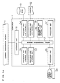
- Fig. 1a is a schematic block diagram of an circuit arrangement of a computer according to a preferred embodiment of the present invention.
- a computer 1 is so arranged by a plurality of processor units 31 to 36; a serial transmission medium 2 for connecting these processor units with each other; and an interface unit 5 for interfacing the serial transmission medium 2 and a common transmission medium 4 used to connect other computers therewith. Then, the computer 1 is connected via the common transmission medium 4 to other computers (not shown).
- this serial transmission medium 2 corresponds to a transmission medium employed in a network, is made of an optical fiber, a coaxial cable, a twisted pair line.
- the processor units 31 to 36 are constructed as a storage unit, a control unit and the like, respectively and have such a basic arrangement of an interface unit with the serial transmission medium 2 and a control function as the processor unit.
- the processor unit 31 corresponds to the control unit having a function as a control section in the computer 1, whereas the processor unit 32 corresponds to the storage unit having a memory.
- the processor unit 33 owns a function for interfacing an input/output device and therewith, is connected to an external input/output device 63. Similarly, the processor unit 34 is connected to an external disk 61, and the processor unit 35 is connected to a printer 62.
- the processors 36 and 37 are equipped with a memory and an I/O control section, and have functions as a single independent computer.
- this arrangement shown in Fig. 1 is merely one example, and therefore the present invention is not limited to this arrangement. That is to say, the combinations between the processor units and internal arrangements of the processor units, and also quantities thereof may be freely changed in accordance with purposes. Similarly, it should be understood that the below-mentioned processing operations are merely an example, and when the internal arrangements of the processor units, combinations between the processor units and also quantities thereof are changed so as to newly perform another processing operation, a computer constructed of these processor units may execute a desirable processing operation.
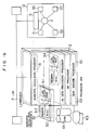
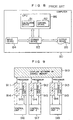
- Fig. 1b is an illustration for showing one example of a mounting structure for the computer shown in Fig. 1a according to the present invention.
- the computer 1 is constructed of the processor units 31 to 35 installed within a single housing, and also the serial transmission path 2 installed within this housing.
- a LAN Local Area Network
- Each of these processor units is so constructed that, as shown in the processor unit 32, these processor units may be detachably connected to this LAN 2 and housing.
- Connectors (not shown) employed at a LAN interface unit for the processor unit and also at the LAN 2 are employed to connect/disconnect the respective processor units.
- An internal arrangement of the respective processor unit is constructed of a calculation processing section (RISC) 312 and a memory 313 other than a LAN interface section 311, as will be discussed later.
- RISC calculation processing section
- the computer 1 stored in this single housing is further connected via the common transmission medium 4 externally provided to another computer 12.
- the computer 1 may be solely employed.
- the LAN 2 is connected via the interface unit to the computer.
- the computer 1 with the arrangement shown in Fig. 1a will perform the following operations.
- a command inputted from the input/output device 63 is processed in the processor unit 33.
- this command processed in the processor unit 33 is to instruct execution of a certain program; data for instructing the execution of this program is transferred to the serial transmission medium 2.
- the processor unit 34 fetches the above-described data from the serial transmission medium 2, and transfers this program to the serial transmission medium 2.
- the processor unit 31 for executing a control of a program receives the program as data from the serial transmission medium 2, and perform the processing operation thereon. As a result of this processing operation, when, for example, an output to the input/output device 63 is required, this processed result is sent as the data to the serial transmission medium 2.
- This data is fetched by, for instance, either the processor unit 33 or 35, and then outputted to either the input/output device 63 or printer 62.
- the computer 1 is connected via the interface unit 5 to the common transmission medium 4, and performs a data processing operation in parallel with a similar computer (not shown) connected to this common transmission medium 4.
- each of the function processor units employed within the computer 1 shown in Fig. 1 is connected via the serial transmission medium 2 to each other, the data transmission/reception among the processor units are performed via this serial transmission medium 2.
- neither shared memory, nor system bus is present in the computer, which is similar to the conventional multiprocessor, so that these processors are loosely coupled with each other in view of hardware and software.
- the computer 1 may be constructed by freely combining a plurality of processors having various functions, and therefore may be realized as a loosely coupled multiprocessor computer.
- expansion and maintenance processing operations may be executed without interrupting a power supply of the computer 1, while performing the processing operations.
- processor units may be connected/disconnected within the computer in a unit of a single processor unit without interrupting the operations of the computer.
- the transfer control for transmitting/receiving data via the serial transmission medium 2 may by performed based upon a previously determined transfer protocol.
- this transfer control method may be realized by utilizing the protocol of the conventional LAN (Local Area Network) and conventional apparatus.
- this transfer control function is realized by an interface section with the serial transmission medium 2.
- this interface section corresponds to an LAN adapter.
- an optical fiber may be employed as the serial transmission medium 2, as will be discussed later.
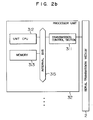
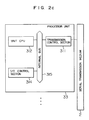
- Fig. 2 is a schematic block diagram for showing an example of an internal arrangement of a processor unit for the computer shown in Fig. 1.
- Fig. 2a represents an internal arrangement of the processor unit 31, in which a transmission control section 311 functioning as an interface with the serial transmission medium 2 and the processor unit 31 is connected to a CPU (central processing unit) 310 via an internal bus 315.
- a transmission control section 311 functioning as an interface with the serial transmission medium 2 and the processor unit 31 is connected to a CPU (central processing unit) 310 via an internal bus 315.
- the CPU 310 controls an overall operation of the computer 1 shown in Fig. 1.
- the transmission control section 311 performs the data transmission/reception between the processor 310 and processors employed within other processor units through the serial transmission medium 2.
- the processor unit 31 owns such a function as the central processing unit (CPU) in the conventional computer.
- Fig. 2b there is shown an internal arrangement of the processor unit 32, in which a memory 313 is connected via an internal bus 315 to both the transmission control unit 311 and a unit CPU 312.
- This memory 313 is operated under control of the unit CPU 312 and owns a function as the storage device in the conventional computer.
- Fig. 2c represents an internal arrangement of the processor unit 33.
- An I/O control section 314 is connected via an internal bus 315 to the transmission control section 311 and unit CPU 312.
- the input/output device 63, disk 61 and printer 62 are connected via this I/O control section 314, which is completely similar to the constructions of the processor unit 34 and 35 shown in Fig. 1.
- the processor unit 33 is operated under control of the unit CPU 312, and has such a function as the input/output device in the conventional computer.
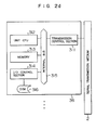
- Fig. 2d indicates an internal construction of the processor unit 36.
- the processor unit 37 shown in Fig. 1 has the similar internal arrangement, and the processor unit 36 has a function as a single computer. That is to say, both a memory 313 and I/O control section 314 are connected via an internal bus 315 to a transmission control unit 311 and a unit CPU 312. Further, a disk 316 as an internal storage medium is connected the I/O control section 314.
- this disk 316 may be provided outside the computer 1 shown in Fig. 1, which is similar to the disk 61 of the processor unit 34. Moreover not only the disk, but also the input/output device or printer may be connected thereto.
- the processing operations are carried out by utilizing the program and data stored in the memory 313 or disk 316 by way of the unit CPU 312 in the processor unit 36.
- the processor unit 36 receives the data derived from other processor units via the serial transmission medium 2 and also sends out the data of the own processor unit to other processor units, if required.
- the computer 1 shown in Fig. 1 may execute a plurality of processing operations with respect to a single job by mutually operating the respective processor units.
- connection arrangements shown in Fig. 2 are merely represented as examples for the computer 1, and therefore may be readily modified in accordance with the desirable function.
- the independent processor units are so connected to the serial transmission medium 2 within the computer 1 shown in Fig. 1, whereby the computer 1 is realized as a loosely coupled multiprocessor computer.
- Fig. 3 is a schematic block diagram for representing an arrangement of a computer when an optical fiber is employed as the serial transmission medium shown in Fig. 1.
- serial transmission medium 2 of the computer 1 shown in Fig. 1 is realized by an optical fiber.
- both an OE converter 317 and an optical connector 318 are additionally employed.
- the OE converter 317 converts an electric signal processed in the transmission control section 311 into an optical (laser light) signal, whereas the optical connector 318 optically connects the OE converter 317 with the serial transmission medium 2 made of an optical fiber.
- Each of the processor units may be disconnected from computer 1 with employment of this optical connector 318, so that the maintenance and expansion processing operations may be performed without interrupting the computation by the computer 1.
- the optical fiber since the optical fiber is employed and the connection/disconnection of the processor units are realized at the optical connector units, it may be prevented that electric arc and the like happen to occur due to the electrical connection/disconnection of the processor units. As a consequence, the electrical connection/disconnection of the processor units during the maintenance and expansion may be more safety carried out even when the computer 1 is under operation.
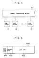
- Fig. 4 is a schematic block diagram for showing a simple construction of a multiprocessor system employing the computers shown in Fig. 1.
- the respective computers 11 to 13 each having the same arrangement as that of the computer shown in Fig. 1 are connected via a common transmission medium 4 to each other, which is completely similar to the conventional multiprocessor system.
- each of the computers 11, 12 and 13 may perform the parallel processing operation, which is similar to that of the conventional computer.
- the power source of this computer must be turned off to cease the functions of the computer before the expansion should be carried out.
- the processing operations for the multiprocessor system may be continuously carried out.
- Fig. 5 schematically illustrates a format of data which are transmitted/received via the serial transmission medium shown in Fig. 1.
- the data 600 is constructed of a content code 601 representative of a content of the data, a control code 602, and a data unit 603.
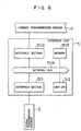
- Fig. 6 is a schematic block diagram for showing an internal arrangement of the interface unit 5 represented in Fig.
- An interface section 501 for interfacing the serial transmission medium 2 and therewith, an interface section 502 for interfacing the common transmission medium 4, and a memory 503 and also a unit CPU 312 are connected via an internal bus 504 to each other.
- the interface section 501 corresponds to a transmission control unit 311 shown in Fig. 2.
- the construction of the interface unit 5 is similar to that of each of the processor units shown in Fig. 1.
- the interface unit 5 may be regarded as the processor unit which executes the data transmission/reception among the computers under the control of the unit CPU 312.
- the interface unit 5 with the above-described construction may be operated as an interface for interfacing the common transmission medium 4 for coupling the computers which perform the parallel processing operations, and the serial transmission medium 2 for coupling the processor units within the computer.
- the data flowing through the serial transmission medium 2 is received by the interface section 501 and transmitted via the internal bus 504 employed in the unit to the interface section 502, if required.
- the interface section 502 sends out the data derived from the interface section 501 to the common transmission medium 4.
- the data flowing through the common transmission medium 4 is fetched by the interface section 502, and then transferred to the interface section 501, if necessary, and to the serial transmission medium 2.
- the memory 503 temporarily stores (buffers) data to be transmitted and/or received, and is used as a storage area for a program and data which are utilized to be processed in the interface sections 501 and 502.
- this interface unit 5 is, in principle, the same as that of each of the processor units shown in Fig. 1. As to the transmission function via the serial transmission medium 2, both the interface unit 5 and processor unit have the similar functions.
- this interface unit 5 an application process may be executed and the I/O control section 314 (refer to Fig. 2c) may be employed.
- the structure of the common transmission medium 4 for coupling the computers may be the same as that of the serial transmission medium 2, and furthermore may be constructed of a normal LAN (Local Area Network).
- the interface unit 5 has such a function corresponding to a so-called "bridge" device in LAN.
- Fig. 7 schematically represents a structure and an operation of the multiprocessor system employing the computer shown in Fig. 1.
- This figure represents such a condition that the data flowing through a single computer and plural computers are transmitted and/or received among the processor units employed in the respective computers.
- this figure represents such a case that a data transmission method with a content code for describing a method to transmit/receive data is utilized.
- Transmission data of a single processor unit, for instance, the processor unit 31 is first broadcasted via the serial transmission medium 21 within the computer 11 including this processor unit 31.
- the interface unit 51 within the computer receives the data which has been broadcasted via the serial transmission medium 21 and broadcasts this data to the common transmission medium 4 among the computers. Then, the interface unit 52 within the computer fetches the data which has been broadcasted via the common transmission medium 4, and the computer 12 broadcasts this data to the serial transmission medium 22 within the computer.
- the way to setting the content code may be determined freely for data transmitted between computers and also for data transmitted between processors of a computer.
- the both codes may be the same in accordance with their protocols.
- the data flowing through the computer directly flows among the computers.
- the content codes are substituted with each other in the interface units 51 and 52. This substitution is made by deleting one content code from data and adding the other code instead thereof to the data.
- the processor units within the computer are loosely coupled with each other, the processor units may be connected/disconnected under on-line condition of the computer system.
- the functions may be expanded and also the maintenance of the computer may be carried out without interruption of the computer jobs which have already been operated when a user makes his command.
- the processing capabilities, functions and reliabilities of the computer may be controlled by adjusting the quantity of the processor units built in this computer, every user need not establish a series of computers with various grades, but also need not replace the computer with a single computer unit.
- the overall system of the computer need not be interrupted during maintenance of the computer system, especially the version-up of the software such as the operating system, and therefore maintenance required for a portion of the computer system may be independently executed in the overall computer system.
- the loads on the computer may be distributed to a plurality of processor units within the computer, the overall processing capabilities of the computer system may be increased.
- processor units within the computer include only the interfaces with the serial transmission medium, then these processor units may communicate with each other, so that these processor units may be constituted as a multiprocessor, irrelevant to the model of the processor units and also the operating system for the processor units.
Landscapes
- Engineering & Computer Science (AREA)
- Computer Security & Cryptography (AREA)
- Computer Networks & Wireless Communication (AREA)
- Signal Processing (AREA)
- Multi Processors (AREA)
- Stored Programmes (AREA)
Description
- The present invention generally relates to an architecture for both a hardware and a software used within a computer, and more specifically, to a computer including a loosely coupled multiprocessor.
- Conventional computers have been developed and have progressed in such a manner that elements are highly integrated and physical distances among the elements are reduced as short as possible in order to increase processing speeds of these computers.
- In Fig. 8, there is shown a schematic block diagram of a basic construction of the conventional computer.
- A
computer 80 includes as five major devices, acalculation device 81, acontrol device 82, astorage device 83, aninput device 84, and anoutput device 85. Further, both thecalculation device 81 and thecontrol device 82 are incorporated into a central processing unit (referred to as a "CPU"). - The
computer 80 with the above-described construction executes the following operations. - First, a program is read out from the
input device 84, and then is stored into a program region within thestorage device 83. Thecontrol device 82 sequentially reads out the programs stored in thisstorage device 83 one by one so as to be decoded, and thereafter sends various instructions to theinput device 84,output device 85 andstorage device 83 which are required to execute commands written in the programs. - When, for instance, the command of the program corresponds to a command (READ command and the like) for requesting a data input, the inputted data is stored into an input region within the
storage device 83. - Also, when the decoded command corresponds to a calculation command, data to be calculated is sent to the
calculation device 81 in which a predetermined calculation is carried out. - Furthermore, data to be outputted is stored into an output region of the
storage device 83. In response to an output command (WRITE command), the data stored in this output region is outputted by utilizing theoutput device 85. - As previously described, the
computer 80 fetches the commands stored in thestorage device 83 one by one, and executes processing operations in accordance with the programmed sequence. - Various system arrangements have been proposed in order to increase reliabilities of the computer systems with employment of such computers.
- Among these computer systems, there is a multiprocessor system. In accordance with the multiprocessor system, a plurality of processors (processing device including CPU as an element) constitute a system for commonly using a main storage device and a file. When malfunction happens to occur, if only failed devices, processors, or a troubled unit employed within the main storage device are isolated from the computer system, the computer system may continue the processing operations, although the processing capabilities of the data are lowered. As a consequence, such a multiprocessor computer system owns better adaptability and therefore is suitable for constituting a large-scale on-line computer system.
- This multiprocessor system may be further understood as one of parallel-processing computer systems.
- "Parallel processing" operations imply that processing operations which have been performed by a single processor employed within the conventional computer, are performed in a parallel form by parallel-operating plural processors. As a result, highspeed processing operations may be realized.
- As to the parallel processing operation, it may be subdivided into SIMD (Single Instruction Multiple Datastream; a single instruction and plural data method), and MIMD (Multiple Instruction Multiple Datastream; a plural-instruction and plural data method), depending upon arrangements of processors and processing ways.
- The "SIMD" method is such a method that a plurality of processors execute plural data in synchronization with each other in response to the same instruction supplied from a central control device. Since each of the processors can parallel-execute the same instruction in this SIMD method, this method is suitable for such a case that similar types of calculations are performed for a large quantity of data.
- In accordance with the MIMD method, on the other hand, each of the processors is independently operable, and a plurality of data processing operations are executed in an asynchronization mode in response to a plurality of different instructions. Since the respective processors are separately operated, control functions are provided within these processors. Also, communication networks to perform information exchanges among the respective processors are provided, which is similar to that of the SIMD method.
- Fig. 9 is a schematic block diagram for representing a system arrangement of the MIMD method.
- A processor (1) 911, a processor (2) 912, and a processor (n) 913 include an ALU (arithmetic logic unit) 914, a
storage unit 915, a control unit (1) 914, a control unit (2) 917, and further a control unit (n) 918, respectively, and are connected to either a coupling network, or a sharedmemory 918. - A multiprocessor system corresponds to one of this MIMD method, and is so constructed that a large number of processors closely communicate with each other with employment of a highspeed coupling network and are operable in a parallel mode with better cooperation.
- Then, the multiprocessor system is roughly categorized into two communication methods effected among the processors.
- Each of processors is operable with sharing a main storage device. The main storage device may be directly accessed by an instruction of the respective processors. If all of storage domains are completely shared, the access traffic to the main storage device becomes large, whereas when the number of the processors is increased, a bottleneck happens to occur and thus performance of the multiprocessor is degraded.
- As a consequence, there are many possibilities to employ the following methods.
- (i) Each of processors is equipped with own local memory, the access of which does not compete with the accesses of other processors, and a shared region is limited to a portion.
- (ii) Each of processors is equipped with a cache memory.
- (iii) A shared memory domain is subdivided into a plurality of partial domains, which will be allocated to each processor.
- A memory shared type multiprocessor corresponds to a tightly coupled multiprocessor, and the total number of processors is suppressed due to the accessing contention to the shared memory, and therefore becomes small normally.
- Communications among processors are performed via I/O ports in a message communication mode. A packet communication method and the like are employed. The message exchange type multiprocessor corresponds to a loosely coupled multiprocessor. The total number of the processors may be selected to be greater than that of the above-described memory shared type multiprocessor, depending upon the communication network condition and applications.
- A computer system comprising a plurality of processors wherein said processors are connected via a transmission medium is disclosed in Proceedings of the IEEE 1984 National Aerospace and Electronics Conference Naecon 84, 21 May 1984, Dayton Convention Cender, pages 201-207.
- In general, conventional computers have been progressed by improving the processing capabilities including the reliabilities. The processing speeds of the elements employed in the conventional computers are tried to be increased, and on the other hand, the processing capabilities are improved by the computer system arrangements. Among these improvements, there is one improving method, i.e., a parallel processing operation by multiprocessor systems.
- In the processors employed in the conventional processor system, the data and control signal communications are performed via the parallel bus within the processors.
- That is to say, each of units is connected via an internal bus to each other, which is similar to the normal computer.
- In Fig. 9, for instance, various signals are mutually transmitted/received via the internal bus among the ALU 914,
storage unit 915 and control unit (1) 915 employed within the processor (1). - As previously described, since the respective processors employed in the multiprocessor system are operable similar to those of the normal computer, when, for instance, the
storage unit 915 in the processor (1) 911 is brought into malfunction, the power source of the processor (1) 911 is turned off, whereby the failedstorage unit 915 is repaired. - Also, even when the function of the processor (1) 911 is expanded, the power source of this processor (1) 911 is once turned off and thereafter must be isolated from the multiprocessor system.
- As previously explained, no specific care has been taken into such expansion and maintenance of the processor per se in the conventional computer system. Therefore, the processing operation required for each of the processors must always be carried out, taking account of the functions and processing operations of other processors. To mutually operate these processors, complex and large-scale management softwares are necessarily required, which may result in lowing the performance of the computer system.
- In addition, when malfunction of processors happens to occur, the malfuncting processors must be isolated from the entire system and therefore the processing capabilities of the computer system are deteriorated.
- A loosely coupled multiprocessor computer with the features included in the first part of
claim 1 is disclosed in Proceedings of the 1988 International Conference on Parallel Processing, Vol. 1, 15 August 1988, pages 410-413. - Further, from EP-A-0 317 828 a computer system containing a serial bus connection between memory arrays and processors is known.
- An object of the present invention is to solve these problems of the conventional computer systems, and to provide such a computer capable of loosely-coupling a CPU and various devices such as storage devices employed in a computer so as to establish a loosely coupled hardware architecture, whereby the respective devices are mutually operable on the loosely couple hardware architecture in order to perform a parallel processing operation at a higher speed; and also capable of performing maintenance as well as expansion processing operations of the computer, while continuing the computer processing operations.
- This object is met by a loosely coupled multiprocessor computer according to
claim 1. Preferred embodiments are disclosed in the depending claims. -
- Fig. 1a is a schematic block diagram for representing a preferred embodiment of a computer according to the present invention;
- Fig. 1b schematically illustrates an example of a computer mounting construction according to the present invention;
- Figs. 2a to 2d are schematic block diagrams for showing internal arrangements of the computer shown in Fig. 1;
- Fig. 3 is a schematic block diagram of an arrangement of a computer employing an optical fiber as a serial transmission medium shown in Fig. 1;
- Fig. 4 is a schematic block diagram for showing a simple construction of a multiprocessor system employing the computer shown in Fig. 1;
- Fig. 5 is an illustration for explaining a
data format 11 transferred/received via the serial transmission medium shown in Fig. 1; - Fig. 6 is a schematic block diagram for representing an internal arrangement of an interface unit shown in Fig. 1;
- Fig. 7 is a schematic block diagram for representing an arrangement of a multiprocessor system employing the computer shown in Fig. 1;
- Fig. 8 is a schematic block diagram for showing a basic arrangement of the conventional computer; and
- Fig. 9 is a schematic block diagram for representing a construction of the MIMD system.
- Various preferred embodiments according to the present invention will now be described with reference to drawings more in detail.
- Fig. 1a is a schematic block diagram of an circuit arrangement of a computer according to a preferred embodiment of the present invention.
- A
computer 1 is so arranged by a plurality ofprocessor units 31 to 36; aserial transmission medium 2 for connecting these processor units with each other; and aninterface unit 5 for interfacing theserial transmission medium 2 and acommon transmission medium 4 used to connect other computers therewith. Then, thecomputer 1 is connected via thecommon transmission medium 4 to other computers (not shown). - In general, this
serial transmission medium 2 corresponds to a transmission medium employed in a network, is made of an optical fiber, a coaxial cable, a twisted pair line. - The
processor units 31 to 36 are constructed as a storage unit, a control unit and the like, respectively and have such a basic arrangement of an interface unit with theserial transmission medium 2 and a control function as the processor unit. - The
processor unit 31 corresponds to the control unit having a function as a control section in thecomputer 1, whereas theprocessor unit 32 corresponds to the storage unit having a memory. - The
processor unit 33 owns a function for interfacing an input/output device and therewith, is connected to an external input/output device 63. Similarly, theprocessor unit 34 is connected to anexternal disk 61, and theprocessor unit 35 is connected to aprinter 62. - Then, the
processors - It should be noted that this arrangement shown in Fig. 1 is merely one example, and therefore the present invention is not limited to this arrangement. That is to say, the combinations between the processor units and internal arrangements of the processor units, and also quantities thereof may be freely changed in accordance with purposes. Similarly, it should be understood that the below-mentioned processing operations are merely an example, and when the internal arrangements of the processor units, combinations between the processor units and also quantities thereof are changed so as to newly perform another processing operation, a computer constructed of these processor units may execute a desirable processing operation.
- Fig. 1b is an illustration for showing one example of a mounting structure for the computer shown in Fig. 1a according to the present invention.
- In this figure, the
computer 1 is constructed of theprocessor units 31 to 35 installed within a single housing, and also theserial transmission path 2 installed within this housing. In Fig. 1a, there is shown a LAN (Local Area Network) employing an optical fiber as theserial transmission path 2. Each of these processor units is so constructed that, as shown in theprocessor unit 32, these processor units may be detachably connected to thisLAN 2 and housing. Connectors (not shown) employed at a LAN interface unit for the processor unit and also at theLAN 2 are employed to connect/disconnect the respective processor units. An internal arrangement of the respective processor unit is constructed of a calculation processing section (RISC) 312 and amemory 313 other than aLAN interface section 311, as will be discussed later. - In the example of Fig. 1b, the
computer 1 stored in this single housing is further connected via thecommon transmission medium 4 externally provided to anothercomputer 12. Alternatively, thecomputer 1 may be solely employed. It should be noted that although not shown in Fig. 1b, theLAN 2 is connected via the interface unit to the computer. - The
computer 1 with the arrangement shown in Fig. 1a will perform the following operations. - A command inputted from the input/
output device 63 is processed in theprocessor unit 33. In case that this command processed in theprocessor unit 33 is to instruct execution of a certain program; data for instructing the execution of this program is transferred to theserial transmission medium 2. When this program has been stored in, for instance, thedisk 61, theprocessor unit 34 fetches the above-described data from theserial transmission medium 2, and transfers this program to theserial transmission medium 2. Theprocessor unit 31 for executing a control of a program receives the program as data from theserial transmission medium 2, and perform the processing operation thereon. As a result of this processing operation, when, for example, an output to the input/output device 63 is required, this processed result is sent as the data to theserial transmission medium 2. This data is fetched by, for instance, either theprocessor unit output device 63 orprinter 62. - It should be noted that a transmission procedure or sequence for transmitting/receiving data via the
serial transmission medium 2, which has been produced by the above-described series of data processing operation, is performed in accordance with a proper transmission procedure (will be described later). - Data transmission/reception among the units the performed via the
serial transmission medium 2 with each other. - It should also be noted that a series of data processing operations may be executed by employing the
processor units - Then, the
computer 1 is connected via theinterface unit 5 to thecommon transmission medium 4, and performs a data processing operation in parallel with a similar computer (not shown) connected to thiscommon transmission medium 4. - As described above, each of the function processor units employed within the
computer 1 shown in Fig. 1 is connected via theserial transmission medium 2 to each other, the data transmission/reception among the processor units are performed via thisserial transmission medium 2. As a consequence, neither shared memory, nor system bus is present in the computer, which is similar to the conventional multiprocessor, so that these processors are loosely coupled with each other in view of hardware and software. - Since the respective processor units are loosely coupled with each other, the
computer 1 may be constructed by freely combining a plurality of processors having various functions, and therefore may be realized as a loosely coupled multiprocessor computer. - Even when, for instance, another processor unit is additionally employed so as to expand a function, and maintenance of a single processor is carried out, expansion and maintenance processing operations may be executed without interrupting a power supply of the
computer 1, while performing the processing operations. - In other words, the processor units may be connected/disconnected within the computer in a unit of a single processor unit without interrupting the operations of the computer.
- It should be noted that the transfer control for transmitting/receiving data via the
serial transmission medium 2 may by performed based upon a previously determined transfer protocol. - Also, this transfer control method may be realized by utilizing the protocol of the conventional LAN (Local Area Network) and conventional apparatus. In this case, this transfer control function is realized by an interface section with the
serial transmission medium 2. Generally speaking, this interface section corresponds to an LAN adapter. - Otherwise, an optical fiber may be employed as the
serial transmission medium 2, as will be discussed later. - Since the same operating systems (i.e., software management program) operable on the respective processor units in the
computer 1 are employed, compatibility or interchangeability among these processor units may be established and the interchanging operation as well as the processing operation for the expansion may be easily performed. - Fig. 2 is a schematic block diagram for showing an example of an internal arrangement of a processor unit for the computer shown in Fig. 1.
- Fig. 2a represents an internal arrangement of the
processor unit 31, in which atransmission control section 311 functioning as an interface with theserial transmission medium 2 and theprocessor unit 31 is connected to a CPU (central processing unit) 310 via aninternal bus 315. - The
CPU 310 controls an overall operation of thecomputer 1 shown in Fig. 1. Thetransmission control section 311 performs the data transmission/reception between theprocessor 310 and processors employed within other processor units through theserial transmission medium 2. - The
processor unit 31 owns such a function as the central processing unit (CPU) in the conventional computer. - In Fig. 2b, there is shown an internal arrangement of the
processor unit 32, in which amemory 313 is connected via aninternal bus 315 to both thetransmission control unit 311 and aunit CPU 312. Thismemory 313 is operated under control of theunit CPU 312 and owns a function as the storage device in the conventional computer. - Fig. 2c represents an internal arrangement of the
processor unit 33. An I/O control section 314 is connected via aninternal bus 315 to thetransmission control section 311 andunit CPU 312. As represented in Fig. 1, the input/output device 63,disk 61 andprinter 62 are connected via this I/O control section 314, which is completely similar to the constructions of theprocessor unit - The
processor unit 33 is operated under control of theunit CPU 312, and has such a function as the input/output device in the conventional computer. - Fig. 2d indicates an internal construction of the
processor unit 36. Theprocessor unit 37 shown in Fig. 1 has the similar internal arrangement, and theprocessor unit 36 has a function as a single computer. That is to say, both amemory 313 and I/O control section 314 are connected via aninternal bus 315 to atransmission control unit 311 and aunit CPU 312. Further, adisk 316 as an internal storage medium is connected the I/O control section 314. - It should be noted that this
disk 316 may be provided outside thecomputer 1 shown in Fig. 1, which is similar to thedisk 61 of theprocessor unit 34. Moreover not only the disk, but also the input/output device or printer may be connected thereto. - As previously described, the processing operations are carried out by utilizing the program and data stored in the
memory 313 ordisk 316 by way of theunit CPU 312 in theprocessor unit 36. Theprocessor unit 36 receives the data derived from other processor units via theserial transmission medium 2 and also sends out the data of the own processor unit to other processor units, if required. - As a result, the
computer 1 shown in Fig. 1 may execute a plurality of processing operations with respect to a single job by mutually operating the respective processor units. - It should be understood that the connection arrangements shown in Fig. 2 are merely represented as examples for the
computer 1, and therefore may be readily modified in accordance with the desirable function. - As previously described, the independent processor units are so connected to the
serial transmission medium 2 within thecomputer 1 shown in Fig. 1, whereby thecomputer 1 is realized as a loosely coupled multiprocessor computer. - Fig. 3 is a schematic block diagram for representing an arrangement of a computer when an optical fiber is employed as the serial transmission medium shown in Fig. 1.
- In other words, the
serial transmission medium 2 of thecomputer 1 shown in Fig. 1 is realized by an optical fiber. - To connect each of processor units to a
serial transmission medium 2 made of an optical fiber, both anOE converter 317 and anoptical connector 318 are additionally employed. - The
OE converter 317 converts an electric signal processed in thetransmission control section 311 into an optical (laser light) signal, whereas theoptical connector 318 optically connects theOE converter 317 with theserial transmission medium 2 made of an optical fiber. - Each of the processor units may be disconnected from
computer 1 with employment of thisoptical connector 318, so that the maintenance and expansion processing operations may be performed without interrupting the computation by thecomputer 1. - More specifically, since the optical fiber is employed and the connection/disconnection of the processor units are realized at the optical connector units, it may be prevented that electric arc and the like happen to occur due to the electrical connection/disconnection of the processor units. As a consequence, the electrical connection/disconnection of the processor units during the maintenance and expansion may be more safety carried out even when the
computer 1 is under operation. - Fig. 4 is a schematic block diagram for showing a simple construction of a multiprocessor system employing the computers shown in Fig. 1.
- The
respective computers 11 to 13 each having the same arrangement as that of the computer shown in Fig. 1 are connected via acommon transmission medium 4 to each other, which is completely similar to the conventional multiprocessor system. - With this arrangement, each of the
computers - Furthermore, if, for instance, the functions of a computer are expanded in the conventional computer system, the power source of this computer must be turned off to cease the functions of the computer before the expansion should be carried out. However, in the
computer 11 according to the loosely coupled multiprocessor computer of the present invention, since the function related only to the expansion processing operation may be interrupted, the processing operations for the multiprocessor system may be continuously carried out. - Next, the data transmission procedure executed among the processor units via the
serial transmission medium 2 shown in Fig. 1 will now be explained. - Fig. 5 schematically illustrates a format of data which are transmitted/received via the serial transmission medium shown in Fig. 1.
- The
data 600 is constructed of acontent code 601 representative of a content of the data, acontrol code 602, and adata unit 603. - In Fig. 1, when data is transmitted from the respective processor units to the
serial transmission medium 2, thecontent code 601 is set into this data. This data is broadcasted (reported) via theserial transmission medium 2 to other processor unit. While investigating thecontent code 601 of the data flowing through thisserial transmission medium 2, each of these processor units may fetch only data which must be required for own processor unit. - Which content code of the data to be fetched, has been set into the
transmission control unit 311 in the respective processor units. - Subsequently, the
interface unit 5 of thecomputer 1 will now be described. - Fig. 6 is a schematic block diagram for showing an internal arrangement of the
interface unit 5 represented in Fig. - An
interface section 501 for interfacing theserial transmission medium 2 and therewith, aninterface section 502 for interfacing thecommon transmission medium 4, and amemory 503 and also aunit CPU 312 are connected via aninternal bus 504 to each other. - The
interface section 501 corresponds to atransmission control unit 311 shown in Fig. 2. As previously stated, the construction of theinterface unit 5 is similar to that of each of the processor units shown in Fig. 1. Theinterface unit 5 may be regarded as the processor unit which executes the data transmission/reception among the computers under the control of theunit CPU 312. - The
interface unit 5 with the above-described construction may be operated as an interface for interfacing thecommon transmission medium 4 for coupling the computers which perform the parallel processing operations, and theserial transmission medium 2 for coupling the processor units within the computer. - That is to say, the data flowing through the
serial transmission medium 2 is received by theinterface section 501 and transmitted via theinternal bus 504 employed in the unit to theinterface section 502, if required. Theinterface section 502 sends out the data derived from theinterface section 501 to thecommon transmission medium 4. - On the other hand, the data flowing through the
common transmission medium 4 is fetched by theinterface section 502, and then transferred to theinterface section 501, if necessary, and to theserial transmission medium 2. - The
memory 503 temporarily stores (buffers) data to be transmitted and/or received, and is used as a storage area for a program and data which are utilized to be processed in theinterface sections - As previously described, the structure of this
interface unit 5 is, in principle, the same as that of each of the processor units shown in Fig. 1. As to the transmission function via theserial transmission medium 2, both theinterface unit 5 and processor unit have the similar functions. In thisinterface unit 5, an application process may be executed and the I/O control section 314 (refer to Fig. 2c) may be employed. - It should be also noted that the structure of the
common transmission medium 4 for coupling the computers may be the same as that of theserial transmission medium 2, and furthermore may be constructed of a normal LAN (Local Area Network). In this case, theinterface unit 5 has such a function corresponding to a so-called "bridge" device in LAN. - Fig. 7 schematically represents a structure and an operation of the multiprocessor system employing the computer shown in Fig. 1.
- This figure represents such a condition that the data flowing through a single computer and plural computers are transmitted and/or received among the processor units employed in the respective computers.
- In particular, this figure represents such a case that a data transmission method with a content code for describing a method to transmit/receive data is utilized.
- Transmission data of a single processor unit, for instance, the
processor unit 31 is first broadcasted via theserial transmission medium 21 within thecomputer 11 including thisprocessor unit 31. - It is possible to determine the data transmission sequence between the
computers - Even in the computers, when the data transmission/reception are carried out with employment of the data having the content code, for instance, the
interface unit 51 within the computer receives the data which has been broadcasted via theserial transmission medium 21 and broadcasts this data to thecommon transmission medium 4 among the computers. Then, theinterface unit 52 within the computer fetches the data which has been broadcasted via thecommon transmission medium 4, and thecomputer 12 broadcasts this data to theserial transmission medium 22 within the computer. - The way to setting the content code may be determined freely for data transmitted between computers and also for data transmitted between processors of a computer. The both codes may be the same in accordance with their protocols. In case of the same setting method, the data flowing through the computer directly flows among the computers. Also, in case of the different setting methods, the content codes are substituted with each other in the
interface units - As previously explained, in accordance with the preferred embodiments of the present invention, since the processor units within the computer are loosely coupled with each other, the processor units may be connected/disconnected under on-line condition of the computer system. As a consequence, to improve the processing capabilities as well as the reliabilities of the computer, the functions may be expanded and also the maintenance of the computer may be carried out without interruption of the computer jobs which have already been operated when a user makes his command.
- Furthermore, since the processing capabilities, functions and reliabilities of the computer may be controlled by adjusting the quantity of the processor units built in this computer, every user need not establish a series of computers with various grades, but also need not replace the computer with a single computer unit.
- In addition, the overall system of the computer need not be interrupted during maintenance of the computer system, especially the version-up of the software such as the operating system, and therefore maintenance required for a portion of the computer system may be independently executed in the overall computer system.
- Also, since the loads on the computer may be distributed to a plurality of processor units within the computer, the overall processing capabilities of the computer system may be increased.
- Thus, if the processor units within the computer include only the interfaces with the serial transmission medium, then these processor units may communicate with each other, so that these processor units may be constituted as a multiprocessor, irrelevant to the model of the processor units and also the operating system for the processor units.
- In addition, since the function distribution and load distribution may be realized within a single computer, these function/load distributions do not depend upon either the computer setting place, or computer user. Namely, the number of processors included in a computer may be changed without stopping user's programs in response to requirement of load distribution in the whole system. To the contrary, when the function/load are distributed among the computers, these load/function distributions depend upon the computer setting place and/or computer user.
- Moreover, since only the specifically restricted processing operations are performed by the respective processor units within the computer, and also these specifically restricted processing operations are combined with each other so as to execute a single job, the operating systems for managing the softwares of the respective processor units may be simplified, resulting in lower cost.
Claims (5)
- A loosely coupled multiprocessor computer comprisinga plurality of functional units (31 - 37) andan internal transmission medium (2) for coupling said functional units with each other, whereineach of said functional units is any ofan input/output control unit for fetching both a program and data derived from an external input device and for outputting processed data to an external output device,a storage unit for storing therein both the program and data inputted from said input/output control unit, anda processing unit for sequentially executing a processing operation of said data based upon the program stored in said storage unit,in which each of said functional units includestransmission control means (311) for transmitting said data and for receiving information via said internal transmission medium, andprocessing means (310, 312) for controlling said transmission control means and for performing a process in each of said functional units,characterised inthat said internal transmission medium (2) is a serial transmission medium, which is connected to a LAN (Local Area Network) (4) via a LAN adapter (5) using the protocol of said LAN, andthat said transmission control means (311) is a LAN interface.
- The loosely coupled multiprocessor computer according to claim 1, wherein an optical fiber is employed as said serial transmission medium (2).
- The loosely coupled multiprocessor computer according to claim 1 or 2, wherein said protocol previously determines a transmission control method of a data transmission effected via said serial transmission medium (2).
- The loosely coupled multiprocessor computer according to claim 1 or 2, wherein a broadcast method is employed as the data transmission sequence effected via said serial transmission medium (2).
- The loosely coupled multiprocessor computer according to claim 1 or 2, wherein said transmission control means (311) sets a content code used for judging whether or not data broadcasted to said serial transmission medium (2) is required, to said broadcasted data as said transmission data.
Applications Claiming Priority (2)
| Application Number | Priority Date | Filing Date | Title |
|---|---|---|---|
| JP336965/89 | 1989-12-26 | ||
| JP33696589 | 1989-12-26 |
Publications (3)
| Publication Number | Publication Date |
|---|---|
| EP0435141A2 EP0435141A2 (en) | 1991-07-03 |
| EP0435141A3 EP0435141A3 (en) | 1993-01-27 |
| EP0435141B1 true EP0435141B1 (en) | 1997-03-05 |
Family
ID=18304247
Family Applications (1)
| Application Number | Title | Priority Date | Filing Date |
|---|---|---|---|
| EP90124636A Expired - Lifetime EP0435141B1 (en) | 1989-12-26 | 1990-12-18 | Computer equipped with plural processors |
Country Status (4)
| Country | Link |
|---|---|
| US (1) | US5361366A (en) |
| EP (1) | EP0435141B1 (en) |
| JP (1) | JPH03223957A (en) |
| DE (1) | DE69030066T2 (en) |
Families Citing this family (18)
| Publication number | Priority date | Publication date | Assignee | Title |
|---|---|---|---|---|
| EP0587918B1 (en) * | 1992-08-19 | 1999-11-03 | Siemens Nixdorf Informationssysteme Aktiengesellschaft | Multiprocessorsystem with caches |
| US5802295A (en) * | 1994-09-12 | 1998-09-01 | Canon Kabushiki Kaisha | Information processing method and system therefor |
| US6786420B1 (en) | 1997-07-15 | 2004-09-07 | Silverbrook Research Pty. Ltd. | Data distribution mechanism in the form of ink dots on cards |
| US6618117B2 (en) | 1997-07-12 | 2003-09-09 | Silverbrook Research Pty Ltd | Image sensing apparatus including a microcontroller |
| US7110024B1 (en) | 1997-07-15 | 2006-09-19 | Silverbrook Research Pty Ltd | Digital camera system having motion deblurring means |
| US6624848B1 (en) | 1997-07-15 | 2003-09-23 | Silverbrook Research Pty Ltd | Cascading image modification using multiple digital cameras incorporating image processing |
| US6690419B1 (en) | 1997-07-15 | 2004-02-10 | Silverbrook Research Pty Ltd | Utilising eye detection methods for image processing in a digital image camera |
| US20040119829A1 (en) | 1997-07-15 | 2004-06-24 | Silverbrook Research Pty Ltd | Printhead assembly for a print on demand digital camera system |
| US6879341B1 (en) | 1997-07-15 | 2005-04-12 | Silverbrook Research Pty Ltd | Digital camera system containing a VLIW vector processor |
| AUPP702098A0 (en) | 1998-11-09 | 1998-12-03 | Silverbrook Research Pty Ltd | Image creation method and apparatus (ART73) |
| AUPQ056099A0 (en) | 1999-05-25 | 1999-06-17 | Silverbrook Research Pty Ltd | A method and apparatus (pprint01) |
| US20030126258A1 (en) * | 2000-02-22 | 2003-07-03 | Conkright Gary W. | Web based fault detection architecture |
| FR2807533B1 (en) * | 2000-04-05 | 2002-07-12 | Inup | COMPUTER FARM WITH SYSTEM FOR TRANSFERRING FILES BETWEEN PROCESSOR CARDS |
| FR2807594A1 (en) * | 2000-04-05 | 2001-10-12 | Inup | COMPUTER FARM SIMULATING A LOCAL AREA NETWORK WITH SIMULATION MONITORING |
| US7213168B2 (en) * | 2003-09-16 | 2007-05-01 | Rockwell Automation Technologies, Inc. | Safety controller providing for execution of standard and safety control programs |
| US20110314256A1 (en) * | 2010-06-18 | 2011-12-22 | Microsoft Corporation | Data Parallel Programming Model |
| US8589867B2 (en) | 2010-06-18 | 2013-11-19 | Microsoft Corporation | Compiler-generated invocation stubs for data parallel programming model |
| CN115173998A (en) * | 2022-07-05 | 2022-10-11 | 浙江中控技术股份有限公司 | Multiprocessor interactive communication method, system and storage medium |
Family Cites Families (3)
| Publication number | Priority date | Publication date | Assignee | Title |
|---|---|---|---|---|
| FR2476349A1 (en) * | 1980-02-15 | 1981-08-21 | Philips Ind Commerciale | DISTRIBUTED DATA PROCESSING SYSTEM |
| US5047925A (en) * | 1985-05-06 | 1991-09-10 | Motorola, Inc. | Logical ring in a virtual single machine |
| EP0317828A3 (en) * | 1987-11-23 | 1990-10-31 | Siemens Aktiengesellschaft | Serial bus in a computer system for internal system communications |
-
1990
- 1990-11-02 JP JP2295328A patent/JPH03223957A/en active Pending
- 1990-12-17 US US07/628,578 patent/US5361366A/en not_active Expired - Lifetime
- 1990-12-18 DE DE69030066T patent/DE69030066T2/en not_active Expired - Fee Related
- 1990-12-18 EP EP90124636A patent/EP0435141B1/en not_active Expired - Lifetime
Also Published As
| Publication number | Publication date |
|---|---|
| JPH03223957A (en) | 1991-10-02 |
| DE69030066T2 (en) | 1997-09-18 |
| US5361366A (en) | 1994-11-01 |
| EP0435141A2 (en) | 1991-07-03 |
| EP0435141A3 (en) | 1993-01-27 |
| DE69030066D1 (en) | 1997-04-10 |
Similar Documents
| Publication | Publication Date | Title |
|---|---|---|
| US5361366A (en) | Computer equipped with serial bus-connected plural processor units providing internal communications | |
| US5590281A (en) | Asynchronous bidirectional application program processes interface for a distributed heterogeneous multiprocessor system | |
| US5408617A (en) | Inter-system communication system for communicating between operating systems using virtual machine control program | |
| US5887165A (en) | Dynamically reconfigurable hardware system for real-time control of processes | |
| US5867648A (en) | High speed heterogeneous coupling of computer systems using channel-to-channel protocol | |
| US7702748B2 (en) | Method and system for computer nodes configured with a plurality of UART channels for serial redirection through with a service processor | |
| CZ385291A3 (en) | Communication system | |
| US4447871A (en) | Data communication system with a front-end-processor | |
| JPH114279A (en) | Advanced intersystem transmission method and mechanism | |
| US4852021A (en) | Centralized command transfer control system for connecting processors which independently send and receive commands | |
| US6009490A (en) | System having plurality of nodes with respective memories and an arbiter for performing arbitration of connection line use for transfer of data between nodes | |
| SK385391A3 (en) | Secret tapping of third side for controlling of collection | |
| JP3651573B2 (en) | Control method for factory automation system, central controller for factory automation system | |
| CA1322609C (en) | Oblivious memory computer networking | |
| JP3364937B2 (en) | Parallel processing unit | |
| US6301508B1 (en) | Automatic instrumentation system | |
| EP0474131A2 (en) | System for enhancing data transfer between application programs and communications programs in telecommunications systems | |
| JPH0452982B2 (en) | ||
| US5954800A (en) | Data communications network adaptor with duplicate interface boards operating alternately in active and stand-by modes | |
| EP0318270B1 (en) | A multiprocessor system and corresponding method | |
| Calta et al. | Enterprise systems connection (ESCON) architecture-system overview | |
| JPS60138664A (en) | Data bus system for devices with different required data bus widths | |
| JP3394834B2 (en) | Debugging method for devices that make up a multiprocessor system | |
| KR200298891Y1 (en) | IPC processing of the transmission board | |
| KR20250094617A (en) | Digital twin edge device capable of interoperating with digital twin system and operating method thereof |
Legal Events
| Date | Code | Title | Description |
|---|---|---|---|
| PUAI | Public reference made under article 153(3) epc to a published international application that has entered the european phase |
Free format text: ORIGINAL CODE: 0009012 |
|
| AK | Designated contracting states |
Kind code of ref document: A2 Designated state(s): DE FR GB |
|
| PUAL | Search report despatched |
Free format text: ORIGINAL CODE: 0009013 |
|
| AK | Designated contracting states |
Kind code of ref document: A3 Designated state(s): DE FR GB |
|
| 17P | Request for examination filed |
Effective date: 19930514 |
|
| 17Q | First examination report despatched |
Effective date: 19940405 |
|
| GRAG | Despatch of communication of intention to grant |
Free format text: ORIGINAL CODE: EPIDOS AGRA |
|
| GRAH | Despatch of communication of intention to grant a patent |
Free format text: ORIGINAL CODE: EPIDOS IGRA |
|
| GRAH | Despatch of communication of intention to grant a patent |
Free format text: ORIGINAL CODE: EPIDOS IGRA |
|
| GRAA | (expected) grant |
Free format text: ORIGINAL CODE: 0009210 |
|
| AK | Designated contracting states |
Kind code of ref document: B1 Designated state(s): DE FR GB |
|
| REF | Corresponds to: |
Ref document number: 69030066 Country of ref document: DE Date of ref document: 19970410 |
|
| ET | Fr: translation filed | ||
| PLBE | No opposition filed within time limit |
Free format text: ORIGINAL CODE: 0009261 |
|
| STAA | Information on the status of an ep patent application or granted ep patent |
Free format text: STATUS: NO OPPOSITION FILED WITHIN TIME LIMIT |
|
| 26N | No opposition filed | ||
| REG | Reference to a national code |
Ref country code: GB Ref legal event code: IF02 |
|
| PGFP | Annual fee paid to national office [announced via postgrant information from national office to epo] |
Ref country code: FR Payment date: 20031124 Year of fee payment: 14 |
|
| PGFP | Annual fee paid to national office [announced via postgrant information from national office to epo] |
Ref country code: GB Payment date: 20031126 Year of fee payment: 14 |
|
| PGFP | Annual fee paid to national office [announced via postgrant information from national office to epo] |
Ref country code: DE Payment date: 20031203 Year of fee payment: 14 |
|
| PG25 | Lapsed in a contracting state [announced via postgrant information from national office to epo] |
Ref country code: GB Free format text: LAPSE BECAUSE OF NON-PAYMENT OF DUE FEES Effective date: 20041218 |
|
| PG25 | Lapsed in a contracting state [announced via postgrant information from national office to epo] |
Ref country code: DE Free format text: LAPSE BECAUSE OF NON-PAYMENT OF DUE FEES Effective date: 20050701 |
|
| GBPC | Gb: european patent ceased through non-payment of renewal fee |
Effective date: 20041218 |
|
| PG25 | Lapsed in a contracting state [announced via postgrant information from national office to epo] |
Ref country code: FR Free format text: LAPSE BECAUSE OF NON-PAYMENT OF DUE FEES Effective date: 20050831 |
|
| REG | Reference to a national code |
Ref country code: FR Ref legal event code: ST |