EP0434539A1 - Pot d'échappement, notamment catalytique, pour les gaz brûlés de moteurs à combustion interne - Google Patents
Pot d'échappement, notamment catalytique, pour les gaz brûlés de moteurs à combustion interne Download PDFInfo
- Publication number
- EP0434539A1 EP0434539A1 EP90403633A EP90403633A EP0434539A1 EP 0434539 A1 EP0434539 A1 EP 0434539A1 EP 90403633 A EP90403633 A EP 90403633A EP 90403633 A EP90403633 A EP 90403633A EP 0434539 A1 EP0434539 A1 EP 0434539A1
- Authority
- EP
- European Patent Office
- Prior art keywords
- strips
- pot
- approximately
- stack
- gases
- Prior art date
- Legal status (The legal status is an assumption and is not a legal conclusion. Google has not performed a legal analysis and makes no representation as to the accuracy of the status listed.)
- Withdrawn
Links
Images

Classifications
-
- F—MECHANICAL ENGINEERING; LIGHTING; HEATING; WEAPONS; BLASTING
- F01—MACHINES OR ENGINES IN GENERAL; ENGINE PLANTS IN GENERAL; STEAM ENGINES
- F01N—GAS-FLOW SILENCERS OR EXHAUST APPARATUS FOR MACHINES OR ENGINES IN GENERAL; GAS-FLOW SILENCERS OR EXHAUST APPARATUS FOR INTERNAL-COMBUSTION ENGINES
- F01N3/00—Exhaust or silencing apparatus having means for purifying, rendering innocuous, or otherwise treating exhaust
- F01N3/08—Exhaust or silencing apparatus having means for purifying, rendering innocuous, or otherwise treating exhaust for rendering innocuous
- F01N3/10—Exhaust or silencing apparatus having means for purifying, rendering innocuous, or otherwise treating exhaust for rendering innocuous by thermal or catalytic conversion of noxious components of exhaust
- F01N3/24—Exhaust or silencing apparatus having means for purifying, rendering innocuous, or otherwise treating exhaust for rendering innocuous by thermal or catalytic conversion of noxious components of exhaust characterised by constructional aspects of converting apparatus
- F01N3/28—Construction of catalytic reactors
- F01N3/2803—Construction of catalytic reactors characterised by structure, by material or by manufacturing of catalyst support
- F01N3/2807—Metal other than sintered metal
- F01N3/281—Metallic honeycomb monoliths made of stacked or rolled sheets, foils or plates
-
- F—MECHANICAL ENGINEERING; LIGHTING; HEATING; WEAPONS; BLASTING
- F01—MACHINES OR ENGINES IN GENERAL; ENGINE PLANTS IN GENERAL; STEAM ENGINES
- F01N—GAS-FLOW SILENCERS OR EXHAUST APPARATUS FOR MACHINES OR ENGINES IN GENERAL; GAS-FLOW SILENCERS OR EXHAUST APPARATUS FOR INTERNAL-COMBUSTION ENGINES
- F01N3/00—Exhaust or silencing apparatus having means for purifying, rendering innocuous, or otherwise treating exhaust
- F01N3/08—Exhaust or silencing apparatus having means for purifying, rendering innocuous, or otherwise treating exhaust for rendering innocuous
- F01N3/10—Exhaust or silencing apparatus having means for purifying, rendering innocuous, or otherwise treating exhaust for rendering innocuous by thermal or catalytic conversion of noxious components of exhaust
- F01N3/24—Exhaust or silencing apparatus having means for purifying, rendering innocuous, or otherwise treating exhaust for rendering innocuous by thermal or catalytic conversion of noxious components of exhaust characterised by constructional aspects of converting apparatus
- F01N3/28—Construction of catalytic reactors
- F01N3/2803—Construction of catalytic reactors characterised by structure, by material or by manufacturing of catalyst support
- F01N3/2807—Metal other than sintered metal
- F01N3/281—Metallic honeycomb monoliths made of stacked or rolled sheets, foils or plates
- F01N3/2814—Metallic honeycomb monoliths made of stacked or rolled sheets, foils or plates all sheets, plates or foils being corrugated
-
- F—MECHANICAL ENGINEERING; LIGHTING; HEATING; WEAPONS; BLASTING
- F01—MACHINES OR ENGINES IN GENERAL; ENGINE PLANTS IN GENERAL; STEAM ENGINES
- F01N—GAS-FLOW SILENCERS OR EXHAUST APPARATUS FOR MACHINES OR ENGINES IN GENERAL; GAS-FLOW SILENCERS OR EXHAUST APPARATUS FOR INTERNAL-COMBUSTION ENGINES
- F01N3/00—Exhaust or silencing apparatus having means for purifying, rendering innocuous, or otherwise treating exhaust
- F01N3/08—Exhaust or silencing apparatus having means for purifying, rendering innocuous, or otherwise treating exhaust for rendering innocuous
- F01N3/10—Exhaust or silencing apparatus having means for purifying, rendering innocuous, or otherwise treating exhaust for rendering innocuous by thermal or catalytic conversion of noxious components of exhaust
- F01N3/24—Exhaust or silencing apparatus having means for purifying, rendering innocuous, or otherwise treating exhaust for rendering innocuous by thermal or catalytic conversion of noxious components of exhaust characterised by constructional aspects of converting apparatus
- F01N3/28—Construction of catalytic reactors
- F01N3/2803—Construction of catalytic reactors characterised by structure, by material or by manufacturing of catalyst support
- F01N3/2807—Metal other than sintered metal
- F01N3/281—Metallic honeycomb monoliths made of stacked or rolled sheets, foils or plates
- F01N3/2821—Metallic honeycomb monoliths made of stacked or rolled sheets, foils or plates the support being provided with means to enhance the mixing process inside the converter, e.g. sheets, plates or foils with protrusions or projections to create turbulence
-
- F—MECHANICAL ENGINEERING; LIGHTING; HEATING; WEAPONS; BLASTING
- F01—MACHINES OR ENGINES IN GENERAL; ENGINE PLANTS IN GENERAL; STEAM ENGINES
- F01N—GAS-FLOW SILENCERS OR EXHAUST APPARATUS FOR MACHINES OR ENGINES IN GENERAL; GAS-FLOW SILENCERS OR EXHAUST APPARATUS FOR INTERNAL-COMBUSTION ENGINES
- F01N3/00—Exhaust or silencing apparatus having means for purifying, rendering innocuous, or otherwise treating exhaust
- F01N3/08—Exhaust or silencing apparatus having means for purifying, rendering innocuous, or otherwise treating exhaust for rendering innocuous
- F01N3/10—Exhaust or silencing apparatus having means for purifying, rendering innocuous, or otherwise treating exhaust for rendering innocuous by thermal or catalytic conversion of noxious components of exhaust
- F01N3/24—Exhaust or silencing apparatus having means for purifying, rendering innocuous, or otherwise treating exhaust for rendering innocuous by thermal or catalytic conversion of noxious components of exhaust characterised by constructional aspects of converting apparatus
- F01N3/28—Construction of catalytic reactors
- F01N3/2839—Arrangements for mounting catalyst support in housing, e.g. with means for compensating thermal expansion or vibration
- F01N3/2842—Arrangements for mounting catalyst support in housing, e.g. with means for compensating thermal expansion or vibration specially adapted for monolithic supports, e.g. of honeycomb type
-
- F—MECHANICAL ENGINEERING; LIGHTING; HEATING; WEAPONS; BLASTING
- F01—MACHINES OR ENGINES IN GENERAL; ENGINE PLANTS IN GENERAL; STEAM ENGINES
- F01N—GAS-FLOW SILENCERS OR EXHAUST APPARATUS FOR MACHINES OR ENGINES IN GENERAL; GAS-FLOW SILENCERS OR EXHAUST APPARATUS FOR INTERNAL-COMBUSTION ENGINES
- F01N2330/00—Structure of catalyst support or particle filter
- F01N2330/02—Metallic plates or honeycombs, e.g. superposed or rolled-up corrugated or otherwise deformed sheet metal
Definitions
- the present invention relates to the internal combustion engine industry and more particularly the treatment of their burnt gases, before discharge into the atmosphere, for less noise and chemical pollution.
- exhaust pipes enclosures where the gases undergo expansion, which lowers the sound level during venting, and possibly additional combustion of the unburnt substances which they contain, by contact with oxidation catalysts based on precious metals.
- Conventional exhaust pipes are generally made of sheets formed to form a series of baffles and expansion chambers, possibly containing a filling of mineral fibers for good deafening.
- the catalytic converters most often contain a catalytic block made of porous ceramic impregnated with catalyst, which has the drawback of being brittle. and to create a large pressure drop forcing the adoption of dimensions greater than those which the catalytic possibilities would allow in order not to unduly brake the engine exhaust and consequently its efficiency.
- Exhaust pipes have been proposed formed by superimposition of sheets capable of receiving a catalytic coating and providing between them a plurality of gas passage channels in laminar flow, which makes it possible to achieve a good part of the aim pursued.
- Such pots are described in particular in French patent No. 2,617,203 where the channels are formed between stacked fluted tapered washers, as well as in United States patent No. 4,186,172 where the channels are formed between two strips, one smooth and the other wavy, coiled together in a cylinder.
- the object of the invention is therefore to produce industrial exhaust pipes improved in particular by the use of a new architecture creating a turbulent flow slowing the gas flow without excessive pressure drop and promoting homogeneous contact of the gases with the walls. coated with catalyst.
- the subject of the invention is an exhaust pipe, in particular catalytic, for the burnt gases of internal combustion engines, comprising a tubular enclosure containing at least one cellular metal structure formed by superposition of metal strips with surfaces of different reliefs, possibly carrying a coating catalytic and determining between them channels multiple tubulars traversed by the gases; - pot characterized in that the reliefs of one face of a strip form a network of parallel half-channels in the general direction of gas flow, while the facing face of another strip forms a complementary circulation network transverse of the gases connecting together at least the adjoining parallel half-channels, thus creating repetitive material and fluid deviations from the flow of the gases, generating turbulence.
- the reliefs of at least one of the strips form grooves arranged in chevrons.
- the overlapping strips can have the same herringbone relief but with a shift in the pattern of the surfaces faced.
- the metal structure is formed by alternating two strips, one of which has regular corrugations parallel to the general direction of flow of the gases and the other of a less deep embossing and not matching, at least partially, with the undulations of the strips which surround it.
- the embossing can form on each face grooves, not parallel to the corrugations, or protuberances in separate studs, regularly distributed.
- the surfaces of the strips are rough, both for slowing the flow of gases and for attaching a catalytic coating to the metal of the strips, and for contacting the catalyst with the gases, roughness, uniformly distributed having a depth of about 0.002 millimeter.
- the cylindrical metallic honeycomb structure is constituted by a joint winding of two strips, inserted in a metal cylinder open at both ends, characterized in that the two rolled strips are secured to one another and to the cylinder only at their reciprocal contact points within a marginal area at each end of the cylinder.
- the honeycomb structure is formed by flat stacking of strips of the same length but of regularly increasing then decreasing transverse dimensions from one side to the other of a cylindrical envelope.
- Such a stack of strips can be kept assembled at at least one of its ends by a metal ferrule with an L-shaped section wedged against an internal shoulder of the enclosure external to the stack.
- the stack can be kept assembled at at least one of its ends by a metal ring having several radial folds giving it an elasticity of insertion of one of its edges against an internal shoulder of the enclosure outside stacking and a span of its opposite edge against the contiguous edge of the stacked strips.
- Efficiency is further improved by dividing the honeycomb structure into a plurality of sections, separated by free spaces and arranged in series, successively crossed by the gases.
- the honeycomb structure of a pot according to the invention can advantageously be formed from refractory stainless steel strips with a high aluminum content, produced by the direct casting technique on a wheel, thermally oxidized and covered with an aluminous coating supporting a catalyst.
- a known material in itself, in particular by European patent applications Nos. 0 232 793 and 0 243 702 is particularly suitable for the forming of strips in the embodiment of the invention as well as for the resistance of the exhaust pipes to mechanical shocks and thermal undergone during use, especially when mounted on motor vehicles.
- strips made of stainless steel stabilized with 18% chromium, of about 0.06 to 0.08 millimeters in thickness, including an aluminum deposit of about 0.01 to 0.02 millimeters, may be used. thick.
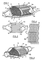
- the exhaust represented in FIGS. 1 and 2 essentially comprises a cylindrical-biconical enclosure 1, formed by conventional assembly of two half-casings of which only one is represented, which contains a cellular metallic structure 2, from which a sector has been removed to better understand its architecture.
- the structure 2 is formed by a flat stack of strips 3 of the same length, but of increasing then decreasing width, from one side to the other of the structure 2 to form a cylindrical envelope with the interior volume of the enclosure 1. This stacking is maintained each time its ends by a metal ring 4, 4 a , having four radial folds 5 inserted between the edges of the stack and an internal shoulder 6, 6 a of the enclosure 1.
- the enclosure 1 a is formed by a cylindrical-conical receptacle 7 on which a frustoconical cap 8 fits.
- the honeycomb structure 2 a similar to that of FIGS. 1 and 2, is maintained at each end by a ferrule 9, 9a, L-section metal whose radial flange 9 comes internally marginally cover the portion of the strips 3a and externally supported respectively against one of the shoulders formed by the conical narrowing of the receptacle 7 and the cap 8.
- the strips used, according to the invention, for the production of cellular structures can have various reliefs, a strip having alternating grooves of ribs forming a first network of parallel half-channels in the general direction of gas flow, being surrounded strips whose reliefs determine a second gas circulation network, not parallel to the first and connecting the half-channels of the first network, at least two by two.
- This architecture creates disturbances to the flow of gases in the first network by interference from the parasitic flows of the second network, which causes the turbulence sought for better efficiency of the exhaust pipes object of the invention.
- FIGS. 4 to 7 illustrate a few examples of combinations of straps suitable for setting work of the invention. For the sake of clarity of representation only two or three strips are drawn partially in superposition, but it is obvious that it is only part of a repetitive assembly.
- FIG. 4 represents the superposition of two identical strips 10, 10 a , with herringbone reliefs determining on each of their faces a network of half-channels with wavy lines.
- a longitudinal offset A between the two strips ensures the interconnection of the half-networks confronted, as shown and, consequently, their interaction.
- the inclinations of the rafters with respect to the general axis can be approximately 3 to 20 °, preferably 6 °.
- FIG. 5 represents the superposition of two strips 11, 12 of different reliefs.
- a first strip 11 has regular corrugations 13 parallel to the general flow of gas and a second sheet 12 faced with a formed embossing grooves 14, 14a perpendicular to the corrugations 13 that bypass disrupting their flow.
- first strip 11 a with regular corrugations 13 a with flat vertices of approximately 0.15 to 0.20 millimeter wide, similar to the strip 11 of FIG. 5, but associated with a second strip 12 is formed having an embossing pads 1, 1 a, separated by e.g., about 4 square millimeters surface, regularly distributed in staggered rows, which depart from the basis of the undulations 13 has the face of the second strip 12 to create thus a more or less anarchic, but repetitive interconnection between the undulations.
- FIG. 6 represents a superposition of three strips 16 a , 16 b , 16 c with similar parallel regular undulations but with different orientations between adjoining strips.
- the strip 16 a is oriented to the left while the strips 16 b and 16 c which surround it are oriented to the right.
- the crossings of the facing grooves create their interconnection-generating turbulence.
- FIG. 8 shows a cylindrical honeycomb structure 2 b constituted by a joint winding 3 b of two superimposed strips, such as those of FIGS. 4 to 7, inserted in a metal cylinder 17.
- the strips are secured to one another and to the cylinder, only at their reciprocal contact points by welding inside the marginal zones 18, 18 a materialized by hatching at each of the ends of the cylinder 17.
- This thus provides a rigid honeycomb structure, easy storage and handling because that not fragile and easy to carry out by known techniques of brazing in particular in an oven.
- FIG. 9 represents another embodiment of an exhaust pipe according to the invention, the enclosure 1 b of two half-casings, similar to that of FIG. 1, contains four partial honeycomb structures 2 c , 2 c ′, 2 c ⁇ , 2 c ⁇ ′, for example such as those of FIGS. 1, 3 and 8, wedged in housings of the enclosure 1 b and separated by intervals 19, 19 ′, 19 ⁇ which facilitate the passage of gases and better efficiency of each partial honeycomb structure.
Landscapes
- Chemical & Material Sciences (AREA)
- Chemical Kinetics & Catalysis (AREA)
- Engineering & Computer Science (AREA)
- Health & Medical Sciences (AREA)
- Toxicology (AREA)
- Combustion & Propulsion (AREA)
- Mechanical Engineering (AREA)
- General Engineering & Computer Science (AREA)
- Exhaust Gas After Treatment (AREA)
Abstract
Pot, renfermant au moins une structure alvéolaire métallique, portant éventuellement un revêtement catalytique, formé par superposition de feuillards (11,11a;12,12a) à surfaces de reliefs différents créant entre eux des réseaux de canaux tubulaires de circulation des gaz présentant des déviations répétitives matérielles et fluidiques génératrices de turbulences. <IMAGE>
Description
- La présente invention concerne l'industrie des moteurs à combustion interne et plus particulièrement le traitement de leurs gaz brûlés, avant rejet dans l'atmosphère, pour une moindre pollution sonore et chimique.
- Ce traitement des gaz est effectué dans des enceintes dites "pots d'échappement" où les gaz subissent une détente, qui abaisse le niveau sonore lors de la mise à l'atmosphère, et éventuellement une combustion complémentaire des imbrûlés qu'ils renferment, par contact avec des catalyseurs d'oxydation à base de métaux précieux.
- Dans la réalisation industrielle des pots d'échappement on recherche le maximum d'efficacité dans un minimum de place, à un moindre coût, pour une conception se prêtant à une fabrication en série, de bonne résistance à l'usage.
- Les pots d'échappement classiques sont généralement réalisés en tôles formées pour constituer une série de chicanes et de chambres de détente, renfermant éventuellement un remplissage en fibres minérales pour un bon assourdissement.
- Les pots catalytiques renferment le plus souvent un bloc catalytique en céramique poreuse imprégnée de catalyseur, qui présente l'inconvénient d'être friable et de créer une importante perte de charge obligeant à adopter des dimensions supérieures à celles que permettraient les possibilités catalytiques afin de ne pas freiner indûment l'échappement du moteur et par suite son rendement.
- On a proposé des pots d'échappement formés par superposition de tôles susceptibles de recevoir un revêtement catalytique et ménageant entre elles une pluralité de canaux de passage des gaz en écoulement laminaire, ce qui permet d'atteindre une bonne partie du but poursuivi. De tels pots sont notamment décrits dans le brevet français n° 2 617 203 où les canaux sont formés entre des rondelles tronconiques canelées empilées, ainsi que dans le brevet des Etats-Unis d'Amérique n° 4 186 172 où les canaux sont formés entre deux feuillards, l'un lisse et l'autre ondulé, enroulés conjointement en un cylindre.
- Cependant, on a pu constater que l'efficacité de tels pots est bien meilleure, surtout du point de vue catalytique, en écoulement turbulent plutôt qu'en écoulement laminaire des gaz.
- L'invention a donc pour but la réalisation industrielle de pots d'échappement métalliques améliorés notamment par l'utilisation d'une nouvelle architecture créant un écoulement turbulent ralentissant le courant gazeux sans perte de charge excessive et favorisant un contact homogène des gaz avec les parois revêtues de catalyseur.
- L'invention a pour objet un pot d'échappement notamment catalytique pour les gaz brûlés de moteurs à combustion interne, comprenant une enceinte tubulaire renfermant au moins une structure métallique alvéolaire formée par superposition de feuillards métalliques à surfaces de reliefs différents, portant éventuellement un revêtement catalytique et déterminant entre eux des canaux tubulaires multiples parcourus par les gaz; ― pot caractérisé en ce que les reliefs d'une face d'un feuillard forment un réseau de demi-canaux parallèles dans le sens général d'écoulement des gaz, tandis que la face affrontée d'un autre feuillard forme un réseau complémentaire de circulation transversale des gaz reliant entre eux au moins les demi-canaux parallèles mitoyens, créant ainsi les déviations répétitives matérielles et fluidiques à l'écoulement des gaz, génératrices de turbulences.
- Suivant un mode de réalisation, les reliefs d'au moins un des feuillards forment des rainures disposées en chevrons. Les feuillards superposés peuvent avoir le même relief en chevrons mais avec un décalage de motif des surfaces affrontées.
- Dans un autre mode de réalisation, la structure métallique est formée par alternance de deux feuillards dont l'un présente des ondulations régulières parallèles à la direction générale d'écoulement des gaz et l'autre un gaufrage moins profond et ne concordant pas, au moins partiellement, avec les ondulations des feuillards qui l'encadrent.
- Le gaufrage peut former sur chaque face des rainures, non parallèles aux ondulations, ou des protubérances en plots séparés, régulièrement répartis.
- On obtient une bonne maniabilité pour le façonnage des structures avec des ondulations d'une profondeur environ cinq à dix fois plus grande que celle du gaufrage.
- Il est avantageux que les surfaces des feuillards soient rugueuses, aussi bien pour freiner l'écoulement des gaz que pour l'accrochage d'un revêtement catalytique sur le métal des feuillards, et que pour le contact du catalyseur avec les gaz, les rugosités, uniformément réparties ayant une profondeur d'environ 0,002 millimètre.
- Suivant une forme constructive, Ia structure alvéolaire métallique cylindrique est constituée par un enroulement conjoint de deux feuillards, inséré dans un cylindre métallique ouvert aux deux extrémités, caractérisée en ce que les deux feuillards enroulés sont solidarisés l'un à l'autre et au cylindre seulement à leurs points de contact réciproques à l'intérieur d'une zone marginale à chacune des extrémités du cylindre.
- Dans une autre forme constructive, la structure alvéolaire est formée par empilage à plat de feuillards de même longueur mais de dimensions transversales régulièrement croissantes puis décroissantes d'un côté à l'autre d'une enveloppe cylindrique.
- Un tel empilage de feuillards peut être maintenu assemblé à au moins une des ses extrémités par une virole métallique à section en L calée contre un épaulement interne de l'enceinte extérieur à l'empilage.
- En variante, l'empilage peut être maintenu assemblé à au moins une de ses extrémités par un anneau métallique présentant plusieurs replis radiaux lui conférant une élasticité d'insertion d'une de ses tranches contre un épaulement interne de l'enceinte à l'extérieur de l'empilage et une portée de sa tranche opposée contre la tranche contiguë des feuillards empilés.
- On obtient une efficacité encore améliorée en répartissant la structure alvéolaire en une pluralité de tronçons, séparés par des espaces libres et disposés en série, traversés successivement par les gaz.
- La structure alvéolaire d'un pot suivant l'invention peut être avantageusement formée de feuillards en acier inoxydable réfractaire à forte teneur en aluminium, élaboré par la technique de coulée directe sur roue, oxydé thermiquement et recouvert d'un revêtement alumineux supportant un catalyseur. Un tel matériau connu en lui-même, notamment par les demandes de brevet européen n°0 232 793 et 0 243 702 se prête particulièrement bien au formage des feuillards dans la réalisation de l'invention ainsi qu'à la résistance des pots d'échappement aux chocs mécaniques et thermiques subis en cours d'utilisation, notamment lorsqu'ils sont montés sur des véhicules automobiles.
- Dans le cas d'une structure réalisée par empilage, il est particulièrement avantageux d'utiliser de l'acier inoxydable aluminié, car ce type de structure ne nécessite pas d'opération de brasage. On pourra utiliser en ce cas des feuillards en acier inoxydable stabilisé à 18% de chrome, d'environ 0,06 à 0,08 millimètre d'épaisseur y compris un dépôt d'aluminium d'environ 0,01 à 0,02 millimètre d'épaisseur.
- L'invention pourra être plus aisément comprise par l'examen et la description détaillée des dessins annexés qui représentent quelques modes de réalisation de l'invention, choisis simplement à titre d'exemple parmi les nombreuses formes d'exécution, adaptations et variantes de l'invention accessibles à un technicien averti.
- Sur ces dessins:
- la figure 1 est une vue schématique, en perspective, avec des parties arrachées pour une meilleure illustration, d'un premier mode de réalisation de pot d'échappement suivant l'invention;
- la figure 2 est une vue schématique, par dessus, avec un demi-carter enlevé, du pot d'échappement de la figure 1;
- la figure 3 est une vue schématique, en perspective, avec une partie de l'enveloppe arrachée, d'une variante du pot d'échappement de la figure 1;
- la figure 4 est une vue schématique partielle en perspective d'un ensemble de deux feuillards superposés, à reliefs en chevrons;
- la figure 5 est une vue schématique, en perspective et partielle d'un autre ensemble de deux feuillards affrontés dans un pot d'échappement suivant l'invention;
- la figure 6 est une vue analogue à celle de la figure 5, d'une variante;
- la figure 7 est une vue schématique en perspective et partielle, d'une autre variante avec superposition de trois feuillards;
- la figure 8 est une vue schématique, en perspective d'une forme de structure alvéolaire cylindrique suivant l'invention; et
- la figure 9 est une vue schématique, par dessus, avec demi-carter enlevé, d'un autre mode de réalisation d'un pot d'échappement suivant l'invention à structure alvéolaire répartie en plusieurs tronçons.
- Sur ces figures, les éléments correspondants sont désignés par les mêmes références numériques, éventuellement affectées d'un indice. Les dimensions et les proportions respectives de ces éléments peuvent ne pas être respectées pour rendre les dessins plus lisibles. Les flèches indiquent les sens privilégiés d'écoulement des gaz.
- Le pot d'échappement représenté sur les figures 1 et 2 comprend essentiellement une enceinte 1 cylindro-bicônique, formée par assemblage classique de deux demi-carters dont un seul est représenté, qui renferme une structure métallique alvéolaire 2, dont un secteur a été enlevé pour permettre de mieux comprendre son architecture. La structure 2 est formée par un empilage à plat de feuillards 3 de même longueur, mais de largeur croissante puis décroissante, d'un côté à l'autre de la structure 2 pour former une enveloppe cylindrique au volume intérieur de l'enceinte 1. Cet empilage est maintenu à chacune de ses extrémités par un anneau 4, 4a, métallique, présentant quatre replis radiaux 5 insérés entre les tranches de l'empilage et un épaulement 6, 6a interne de l'enceinte 1. Ces replis 5 donnent de l'élasticité aux anneaux 4, 4a et en éloignant la majeure partie de leur circonférence de la paroi latérale de l'enceinte 1, offrant ainsi une butée presque continue aux tranches des feuillards 3 et un calage efficace de la structure 2 entre les épaulements 6, 6a.
- Dans la variante de la figure 3, l'enceinte 1a est formée d'un réceptacle 7 cylindro-cônique sur lequel s'emboîte une coiffe troncônique 8. La structure alvéolaire 2a, analogue à celle des figures 1 et 2, est maintenue à chaque extrémité par une virole 9, 9a, métallique à section en L dont l'aile radiale 9 vient intérieurement recouvrir marginalement la tranche des feuillards 3a et extérieurement prend respectivement appui contre l'un des épaulements formés par les rétrécissements côniques du réceptacle 7 et de la coiffe 8.
- Les feuillards utilisés, suivant l'invention, pour la réalisation de structures alvéolaires peuvent avoir des reliefs variés, un feuillard présentant des rainures alternées de nervures formant un premier réseau de demi-canaux parallèles dans le sens général d'écoulement des gaz, étant entouré de feuillards dont les reliefs déterminent un second réseau de circulation des gaz, non parallèle au premier et mettant en communication les demi-canaux du premier réseau, au moins deux par deux. Cette architecture crée des perturbations à l'écoulement des gaz dans le premier réseau par ingérence des écoulements parasites du second réseau, ce qui provoque les turbulences recherchées pour une meilleure efficacité des pots d'échappement objet de l'invention.
- Les figures 4 à 7 illustrent quelques exemples d'associations de feuillards convenant à la mise en oeuvre de l'invention. Pour une bonne clarté de la représentation seuls deux ou trois feuillards sont dessinés partiellement en superposition, mais il est bien évident qu'il s'agit seulement d'une partie d'un assemblage répétitif.
- La figure 4 représente la superposition de deux feuillards 10, 10a, identiques, à reliefs en chevrons déterminant sur chacune de leurs faces un réseau de demi-canaux à tracé ondulé. Un décalage longitudinal A entre les deux feuillards assure l'interconnexion des demi-réseaux affrontés, comme représenté et, par suite, leur interaction. Les inclinaisons des chevrons par rapport à l'axe général peuvent être d'environ 3 à 20°, de préférence 6°.
- La figure 5 représente la superposition de deux feuillards 11, 12 de reliefs différents. Un premier feuillard 11 présente des ondulations régulières 13 parallèles à l'écoulement général des gaz et un second feuillard 12 affronté présente un gaufrage formé de rainures 14, 14a perpendiculaires aux ondulations 13 qu'elles court-circuitent en perturbant leur écoulement.
- Dans la variante de la figure 6, on retrouve un premier feuillard 11a à ondulations régulières 13a, à sommets plats d'environ 0,15 à 0,20 millimètre de large, analogue au feuillard 11 de la figure 5, mais associé à un second feuillard 12a présentant un gaufrage formé de plots 1, 1a, séparés par exemple d'environ 4 millimètres carrés de surface, régulièrement répartis en quinconce, qui éloignent de la base des ondulations 13a la face du second feuillard 12a créant ainsi une interconnexion plus ou moins anarchique, mais répétitive entre les ondulations.
- La figure 6 représente une superposition de trois feuillards 16a, 16b, 16c à ondulations régulières parallèles analogues mais d'orientations différentes entre feuillards contigus. Ainsi, sur le dessin, le feuillard 16a est orienté à gauche tandis que les feuillards 16b et 16c qui l'encadrent sont orientés à droite. Les croisements des rainures affrontées créent leur interconnexion-génératrice de turbulences.
- En pratique, on utilisera avantageusement des feuillards en acier inoxydable réfractaire à forte teneur en aluminium d'environ 0,03 à 0,08 millimètre d'épaisseur à surface rugueuse présentant les uns 11, 11a, 17 des ondulations d'environ 1 millimètre de profondeur et les autres 12, 12a un gaufrage d'environ 0,15 à 0,20 millimètre de creux. De tels feuillards peuvent être enroulés en spirale sur eux-mêmes, parallèlement à l'axe des ondulations.
- La figure 8 représente une structure alvéolaire 2b cylindrique constituée par un enroulement 3b conjoint de deux feuillards superposés, tels ceux des figures 4 à 7, insérés dans un cylindre métallique 17. Les feuillards sont solidarisés l'un à l'autre et au cylindre, seulement à leurs points de contact réciproques par soudure à l'intérieur des zones marginales 18, 18a matérialisées par des hâchures à chacune des extrémités du cylindre 17. On dispose ainsi d'une structure alvéolaire rigide, de stockage et manipulation aisés parce que non fragile et facile à réaliser par les techniques connues de brasage notamment dans un four.
- La figure 9 représente une autre forme de réalisation d'un pot d'échappement suivant l'invention, dont l'enceinte 1b en deux demi-carters, analogue à celle de la figure 1, renferme quatre structures alvéolaires partielles 2c, 2c′, 2c˝, 2c ˝′, par exemple telles que celles des figures 1, 3 et 8, calées dans des logements de l'enceinte 1b et séparées par des intervalles 19, 19′, 19˝ qui facilitent le passage des gaz et une meilleure efficacité de chaque structure alvéolaire partielle.
Claims (6)
- Pot d'échappement, notamment catalytique, pour les gaz brûlés de moteurs à combustion interne, comprenant une enceinte tubulaire (1), renfermant au moins une structure métallique alvéolaire (2) formée par superposition de feuillards métalliques (3) à surfaces de reliefs différents, portant éventuellement un revêtement catalytique et déterminant entre eux des canaux tubulaires multiples parcourus par les gaz; ― pot caractérisé en ce que la structure métallique est formée par alternance de deux feuillards dont l'un (11, 11a) présente des ondulations (13, 13a) régulières parallèles à la direction générale d'écoulement des gaz et l'autre (12, 12a) un gaufrage (14, 15) moins profond et ne concordant pas, au moins partiellement, avec les ondulations des feuillards qui l'encadrent, formant des rainures (14, 14a) non parallèles aux ondulations (13), ou des protubérances en plots (15, 15a) séparés régulièrement répartis, les ondulations (12, 12a) ayant une profondeur environ 5 à 10 fois plus grande que celle du gaufrage (14, 15).
- Pot, suivant la revendication 1, caractérisé en ce que les feuillards ont une épaisseur d'environ 0,03 à 0,08 millimètre, les ondulations ont une profondeur d'environ 1 millimètre et le gaufrage a une profondeur d'environ 0,15 à 0,20 millimètres.
- Pot, suivant l'une des revendications 1 et 2, dont les surfaces des feuillards sont rugueuses, caractérisé en ce que les rugosités, uniformément réparties, ont une profondeur d'environ 0,002 millimètre.
- Pot, suivant l'une des revendications 1 à 3, dont la structure alvéolaire (2b) métallique cylindrique est constituée par un enroulement conjoint de deux feuillards (3b), inséré dans un cylindre métallique (17) ouvert aux deux extrémités, caractérisé en ce que les deux feuillards enroulés (3b) sont solidarisés l'un à l'autre et au cylindre (17) seulement à leurs points de contact réciproques situés à l'intérieur d'une zone marginale (18, 18a) à chacune des extrémités du cylindre.
- Pot, suivant l'une des revendications 1 à 4, à structure alvéolaire (2, 2a) formée par empilage à plat de feuillards (3) de même longueur mais de dimensions transversales régulièrement croissantes puis décroissantes d'un côté à l'autre d'une enveloppe cylindrique, l'empilage de feuillards étant maintenu assemblé à au moins une de ses extrémités par une virole métallique (9, 9a) à section en L calée contre un épaulement interne de l'enceinte à l'extérieur de l'empilage, pot caractérisé en ce que l'empilage de feuillards est maintenu assemblé à au moins une de ses extrémités par un anneau métallique (4, 4a) présentant plusieurs replis radiaux (5) lui confèrent une élasticité d'insertion d'une de ses tranches contre un épaulement interne (6) de l'enceinte à l'extérieur de l'empilage et une portée de sa tranche opposée contre la tranche contiguë des feuillards (3) empilés.
- Pot, suivant l'une des revendications 1 à 5, caractérisé en ce que sa structure alvéolaire est formée de feuillards en acier inoxydable réfractaire à forte teneur en aluminium, élaborés par la technique de coulée directe sur roue, à surface abrasée, oxydés thermiquement et recouverts d'un revêtement alumineux supportant un catalyseur.
Applications Claiming Priority (2)
| Application Number | Priority Date | Filing Date | Title |
|---|---|---|---|
| FR8917095 | 1989-12-22 | ||
| FR8917095A FR2656376B1 (fr) | 1989-12-22 | 1989-12-22 | Pot d'echappement, notamment catalytique, pour les gaz brules de moteurs a combustion interne. |
Publications (1)
| Publication Number | Publication Date |
|---|---|
| EP0434539A1 true EP0434539A1 (fr) | 1991-06-26 |
Family
ID=9388895
Family Applications (1)
| Application Number | Title | Priority Date | Filing Date |
|---|---|---|---|
| EP90403633A Withdrawn EP0434539A1 (fr) | 1989-12-22 | 1990-12-18 | Pot d'échappement, notamment catalytique, pour les gaz brûlés de moteurs à combustion interne |
Country Status (2)
| Country | Link |
|---|---|
| EP (1) | EP0434539A1 (fr) |
| FR (1) | FR2656376B1 (fr) |
Cited By (8)
| Publication number | Priority date | Publication date | Assignee | Title |
|---|---|---|---|---|
| WO1997027385A1 (fr) * | 1996-01-22 | 1997-07-31 | Institut Français Du Petrole | Precipitateur pour combustion a l'echappement de moteurs diesel ou essence, et procede associe |
| JP2000093775A (ja) * | 1998-09-25 | 2000-04-04 | Man Nutzfahrzeuge Ag | 交差通路型混合機 |
| WO2001063104A1 (fr) * | 2000-02-22 | 2001-08-30 | Engelhard Corporation | SYSTEME DE REDUCTION DES EMISSION DE NOx TRANSITOIRE |
| WO2002090734A1 (fr) * | 2001-05-07 | 2002-11-14 | Emitec Gesellschaft Für Emissionstechnologie Mbh | Tole a structure de glissement, corps en nid d'abeilles et procede de fabrication dudit corps |
| WO2004020902A1 (fr) * | 2002-08-30 | 2004-03-11 | Alstom Technology Ltd | Procede et dispositif de melange de flux fluidiques |
| EP2010764A4 (fr) * | 2006-04-24 | 2010-05-19 | Ecocat Oy | Substrat comportant une ou plusieurs feuilles ondulees et un ou plusieurs canaux pour traiter les gaz d'echappement de moteurs a combustion |
| WO2010122003A1 (fr) * | 2009-04-24 | 2010-10-28 | Emitec Gesellschaft Für Emissionstechnologie Mbh | Couche formée d'une tôle comprenant des structures anti-diffusion, et corps métallique en nid-d'abeilles présentant au moins une telle couche formée d'une tôle |
| GB2589890A (en) * | 2019-12-11 | 2021-06-16 | Rolls Royce Plc | Catalytic converters |
Citations (9)
| Publication number | Priority date | Publication date | Assignee | Title |
|---|---|---|---|---|
| GB1491199A (en) * | 1974-10-25 | 1977-11-09 | Atomic Energy Authority Uk | Catalyst bodies and to a method of manufacturing such bodies |
| GB2001547A (en) * | 1977-07-26 | 1979-02-07 | Sueddeutsche Kuehler Behr | Carrier matrix for a catalytic reactor for exhaust-gas purification of internal combustion engines |
| GB2079174A (en) * | 1980-07-10 | 1982-01-20 | Gen Motors Corp | Wound foil catalytic converter structure and method for manufacturing same |
| EP0117602A2 (fr) * | 1983-02-28 | 1984-09-05 | General Motors Corporation | Substrat pour catalyseur |
| EP0136515A2 (fr) * | 1983-09-05 | 1985-04-10 | INTERATOM Gesellschaft mit beschränkter Haftung | Support de catalyseur métallique à rainures additionnelles pour les gaz d'échappement |
| GB2174615A (en) * | 1985-05-11 | 1986-11-12 | Sueddeutsche Kuehler Behr | Matrix for a catalytic reactor for waste gas cleaning |
| EP0289817A1 (fr) * | 1987-04-18 | 1988-11-09 | Thyssen Edelstahlwerke AG | Elément nid d'abeilles pour la purification des gaz d'échappement de machines à combustion interne |
| DE8816137U1 (de) * | 1987-12-28 | 1989-04-06 | Usui Kokusai Sangyo K.K., Shizuoka | Trägerkörper für Abgaskatalysatoren |
| EP0245737B1 (fr) * | 1986-05-12 | 1989-08-23 | INTERATOM Gesellschaft mit beschränkter Haftung | Corps en forme de nid d'abeilles, en particulier support pour catalyseur, avec des tôles métalliques superposées, repliées en boucles de sens contraire, et son procédé de fabrication |
Family Cites Families (7)
| Publication number | Priority date | Publication date | Assignee | Title |
|---|---|---|---|---|
| US3953176A (en) * | 1973-05-22 | 1976-04-27 | Texas Instruments Incorporated | Catalytic converter |
| CA1102706A (fr) * | 1977-05-06 | 1981-06-09 | Rainer Scholz | Catalyseur homogene en metal pour eliminer les composants toxiques en presence dans les gaz d'echappement des moteurs a combustion interne |
| DE2759559C2 (de) * | 1977-07-26 | 1985-06-27 | Süddeutsche Kühlerfabrik Julius Fr. Behr GmbH & Co. KG, 7000 Stuttgart | Matrix für einen katalytischen Reaktor zur Abgasreinigung bei Brennkraftmaschinen |
| EP0277477B1 (fr) * | 1987-01-15 | 1990-05-16 | Emitec Gesellschaft für Emissionstechnologie mbH | Support de catalyseur métallique à enveloppe tubulaire raccourcie |
| US4755360A (en) * | 1987-02-03 | 1988-07-05 | Avco Corporation | Catalytic converter for gas turbine bleed air extraction |
| DE8712267U1 (de) * | 1987-09-10 | 1987-10-22 | Süddeutsche Kühlerfabrik Julius Fr. Behr GmbH & Co KG, 7000 Stuttgart | Trägerkörper für die Herstellung eines katalytischen Reaktors zur Abgasreinigung |
| US4782570A (en) * | 1987-11-16 | 1988-11-08 | General Motors Corporation | Fabrication and assembly of metal catalytic converter catalyst substrate |
-
1989
- 1989-12-22 FR FR8917095A patent/FR2656376B1/fr not_active Expired - Fee Related
-
1990
- 1990-12-18 EP EP90403633A patent/EP0434539A1/fr not_active Withdrawn
Patent Citations (9)
| Publication number | Priority date | Publication date | Assignee | Title |
|---|---|---|---|---|
| GB1491199A (en) * | 1974-10-25 | 1977-11-09 | Atomic Energy Authority Uk | Catalyst bodies and to a method of manufacturing such bodies |
| GB2001547A (en) * | 1977-07-26 | 1979-02-07 | Sueddeutsche Kuehler Behr | Carrier matrix for a catalytic reactor for exhaust-gas purification of internal combustion engines |
| GB2079174A (en) * | 1980-07-10 | 1982-01-20 | Gen Motors Corp | Wound foil catalytic converter structure and method for manufacturing same |
| EP0117602A2 (fr) * | 1983-02-28 | 1984-09-05 | General Motors Corporation | Substrat pour catalyseur |
| EP0136515A2 (fr) * | 1983-09-05 | 1985-04-10 | INTERATOM Gesellschaft mit beschränkter Haftung | Support de catalyseur métallique à rainures additionnelles pour les gaz d'échappement |
| GB2174615A (en) * | 1985-05-11 | 1986-11-12 | Sueddeutsche Kuehler Behr | Matrix for a catalytic reactor for waste gas cleaning |
| EP0245737B1 (fr) * | 1986-05-12 | 1989-08-23 | INTERATOM Gesellschaft mit beschränkter Haftung | Corps en forme de nid d'abeilles, en particulier support pour catalyseur, avec des tôles métalliques superposées, repliées en boucles de sens contraire, et son procédé de fabrication |
| EP0289817A1 (fr) * | 1987-04-18 | 1988-11-09 | Thyssen Edelstahlwerke AG | Elément nid d'abeilles pour la purification des gaz d'échappement de machines à combustion interne |
| DE8816137U1 (de) * | 1987-12-28 | 1989-04-06 | Usui Kokusai Sangyo K.K., Shizuoka | Trägerkörper für Abgaskatalysatoren |
Cited By (21)
| Publication number | Priority date | Publication date | Assignee | Title |
|---|---|---|---|---|
| WO1997027385A1 (fr) * | 1996-01-22 | 1997-07-31 | Institut Français Du Petrole | Precipitateur pour combustion a l'echappement de moteurs diesel ou essence, et procede associe |
| JP2000093775A (ja) * | 1998-09-25 | 2000-04-04 | Man Nutzfahrzeuge Ag | 交差通路型混合機 |
| EP0988886A3 (fr) * | 1998-09-25 | 2001-12-12 | MAN Nutzfahrzeuge Aktiengesellschaft | Mélangeur à canaux croisés compacte |
| WO2001063104A1 (fr) * | 2000-02-22 | 2001-08-30 | Engelhard Corporation | SYSTEME DE REDUCTION DES EMISSION DE NOx TRANSITOIRE |
| US6311484B1 (en) | 2000-02-22 | 2001-11-06 | Engelhard Corporation | System for reducing NOx transient emission |
| US6446430B1 (en) | 2000-02-22 | 2002-09-10 | Engelhard Corporation | System for reducing NOx transient emission |
| CN1317491C (zh) * | 2001-05-07 | 2007-05-23 | 排放技术有限公司 | 蜂窝体及其制造方法 |
| WO2002090734A1 (fr) * | 2001-05-07 | 2002-11-14 | Emitec Gesellschaft Für Emissionstechnologie Mbh | Tole a structure de glissement, corps en nid d'abeilles et procede de fabrication dudit corps |
| US7101602B2 (en) | 2001-05-07 | 2006-09-05 | Emitec Gesellschaft Fuer Emissionstechnologie Mbh | Sheet-metal foil with sliding structure, honeycomb body and process for producing the same |
| RU2287710C2 (ru) * | 2001-05-07 | 2006-11-20 | Эмитек Гезельшафт Фюр Эмиссионстехнологи Мбх | Лист фольги с профильной структурой скольжения, сотовый элемент и способ его изготовления |
| US7976304B2 (en) | 2002-08-30 | 2011-07-12 | Alstom Technology Ltd | Method and device for mixing fluid flows |
| WO2004020902A1 (fr) * | 2002-08-30 | 2004-03-11 | Alstom Technology Ltd | Procede et dispositif de melange de flux fluidiques |
| EP2010764A4 (fr) * | 2006-04-24 | 2010-05-19 | Ecocat Oy | Substrat comportant une ou plusieurs feuilles ondulees et un ou plusieurs canaux pour traiter les gaz d'echappement de moteurs a combustion |
| US8070847B2 (en) | 2006-04-24 | 2011-12-06 | Ecocat Oy | Substrate having corrugated sheet(s) and channel(s) for treating exhaust gases of combustion engines |
| WO2010122003A1 (fr) * | 2009-04-24 | 2010-10-28 | Emitec Gesellschaft Für Emissionstechnologie Mbh | Couche formée d'une tôle comprenant des structures anti-diffusion, et corps métallique en nid-d'abeilles présentant au moins une telle couche formée d'une tôle |
| CN102414410A (zh) * | 2009-04-24 | 2012-04-11 | 排放技术有限公司 | 具有防扩散结构的板层以及包括至少一个这种板层的金属蜂窝体 |
| US8288010B2 (en) | 2009-04-24 | 2012-10-16 | Emitec Gesellschaft Fuer Emissionstechnologie Mbh | Sheet-metal layer with anti-diffusion structures and metallic honeycomb body with at least one such sheet-metal layer |
| KR101308274B1 (ko) | 2009-04-24 | 2013-09-13 | 에미텍 게젤샤프트 퓌어 에미시온스테크놀로기 엠베하 | 확산 방지 구조를 포함하는 시트-금속층 및 적어도 하나의 그와 같은 시트-금속층을 포함하는 금속 허니콤체 |
| CN102414410B (zh) * | 2009-04-24 | 2014-04-30 | 排放技术有限公司 | 具有防扩散结构的板层以及包括至少一个这种板层的金属蜂窝体 |
| RU2523514C2 (ru) * | 2009-04-24 | 2014-07-20 | Эмитек Гезельшафт Фюр Эмиссионстехнологи Мбх | Металлический слой с антидиффузионными структурами и металлический сотовый элемент с по меньшей мере одним таким металлическим слоем |
| GB2589890A (en) * | 2019-12-11 | 2021-06-16 | Rolls Royce Plc | Catalytic converters |
Also Published As
| Publication number | Publication date |
|---|---|
| FR2656376A1 (fr) | 1991-06-28 |
| FR2656376B1 (fr) | 1994-04-29 |
Similar Documents
| Publication | Publication Date | Title |
|---|---|---|
| JP4249489B2 (ja) | 内燃焼エンジンの排気ガスに含まれる粒子を濾過する濾過体 | |
| EP1660213B1 (fr) | Bloc filtrant pour la filtration de particules contenues dans les gaz d echappement d un moteur a combustion interne. | |
| US4753918A (en) | Growth compensating metallic exhaust gas catalyst carrier body and metal sheet for manufacturing the same | |
| KR20040083099A (ko) | 허니콤 필터 | |
| JP2002301325A (ja) | ハニカム構造体及びそのアッセンブリ | |
| WO2003002231A1 (fr) | Corps a structure alveolaire | |
| EP3311095B1 (fr) | Echangeur de chaleur et procédé de fabrication associé | |
| EP1063486B1 (fr) | Echangeur de chaleur à plaques, en particulier refroidisseur d'huile pour véhicule automobile | |
| FR2656376A1 (fr) | Pot d'echappement, notamment catalytique, pour les gaz brules de moteurs a combustion interne. | |
| EP2145661B1 (fr) | Structure en nid d'abeille bouchée | |
| JP4571647B2 (ja) | 内燃機関の排気ガス中に存在する微粒子をろ過するためのブロック | |
| CN100523445C (zh) | 用于过滤内燃机的排放气体中含有的颗粒的过滤块 | |
| CN108854319B (zh) | 蜂窝过滤器 | |
| FR2773588A1 (fr) | Convertisseur catalytique destine a un pot d'echappement d'un moteur de faible puissance | |
| FR2695326A1 (fr) | Matrice métallique de réacteur catalytique pour le traitement des gaz de combustion. | |
| JP2007523739A (ja) | 内燃機関の排気ガス中に存在する微粒子をろ過するためのブロック | |
| CA1283865C (fr) | Methode pour optimiser les caracteristiques de gerbage de feuilles metalliques ondulees | |
| US7736717B2 (en) | Honeycomb body with double tubular casing | |
| US6602477B2 (en) | Metal honeycomb structure | |
| CN101960110A (zh) | 具有柔性区的蜂窝体 | |
| KR20080048059A (ko) | 환형 허니콤체의 제조방법, 및 환형 허니콤체 | |
| EP1063488B1 (fr) | Echangeur de chaleur à plaques, notamment pour refroidir une huile d'un véhicule automobile | |
| JP2016196824A (ja) | ハニカム構造体 | |
| EP1443214A1 (fr) | Stator d'une pompe turbomoléculaire | |
| FR2622632A1 (fr) | Pot d'echappement catalytique pour gaz brules de moteurs thermiques |
Legal Events
| Date | Code | Title | Description |
|---|---|---|---|
| PUAI | Public reference made under article 153(3) epc to a published international application that has entered the european phase |
Free format text: ORIGINAL CODE: 0009012 |
|
| AK | Designated contracting states |
Kind code of ref document: A1 Designated state(s): DE FR GB IT |
|
| 17P | Request for examination filed |
Effective date: 19911105 |
|
| 17Q | First examination report despatched |
Effective date: 19920707 |
|
| STAA | Information on the status of an ep patent application or granted ep patent |
Free format text: STATUS: THE APPLICATION IS DEEMED TO BE WITHDRAWN |
|
| 18D | Application deemed to be withdrawn |
Effective date: 19930119 |