EP0434530B1 - Speichervorrichtung für Lichtwellenleiter in einem Verteilerschrank - Google Patents
Speichervorrichtung für Lichtwellenleiter in einem Verteilerschrank Download PDFInfo
- Publication number
- EP0434530B1 EP0434530B1 EP90403608A EP90403608A EP0434530B1 EP 0434530 B1 EP0434530 B1 EP 0434530B1 EP 90403608 A EP90403608 A EP 90403608A EP 90403608 A EP90403608 A EP 90403608A EP 0434530 B1 EP0434530 B1 EP 0434530B1
- Authority
- EP
- European Patent Office
- Prior art keywords
- compartments
- partitions
- rack
- fiber
- floor
- Prior art date
- Legal status (The legal status is an assumption and is not a legal conclusion. Google has not performed a legal analysis and makes no representation as to the accuracy of the status listed.)
- Expired - Lifetime
Links
- 230000003287 optical effect Effects 0.000 title description 2
- 239000000835 fiber Substances 0.000 claims description 58
- 238000005192 partition Methods 0.000 claims description 38
- 239000013307 optical fiber Substances 0.000 claims description 7
- 238000000605 extraction Methods 0.000 claims description 4
- 238000003780 insertion Methods 0.000 claims description 3
- 230000037431 insertion Effects 0.000 claims description 2
- 230000002093 peripheral effect Effects 0.000 description 9
- 210000004907 gland Anatomy 0.000 description 3
- 238000000926 separation method Methods 0.000 description 3
- 238000004804 winding Methods 0.000 description 2
- 239000000463 material Substances 0.000 description 1
- 238000012986 modification Methods 0.000 description 1
- 230000004048 modification Effects 0.000 description 1
- 238000000465 moulding Methods 0.000 description 1
- 230000008707 rearrangement Effects 0.000 description 1
Images

Classifications
-
- G—PHYSICS
- G02—OPTICS
- G02B—OPTICAL ELEMENTS, SYSTEMS OR APPARATUS
- G02B6/00—Light guides; Structural details of arrangements comprising light guides and other optical elements, e.g. couplings
- G02B6/44—Mechanical structures for providing tensile strength and external protection for fibres, e.g. optical transmission cables
- G02B6/4439—Auxiliary devices
- G02B6/444—Systems or boxes with surplus lengths
- G02B6/4453—Cassettes
- G02B6/4454—Cassettes with splices
-
- G—PHYSICS
- G02—OPTICS
- G02B—OPTICAL ELEMENTS, SYSTEMS OR APPARATUS
- G02B6/00—Light guides; Structural details of arrangements comprising light guides and other optical elements, e.g. couplings
- G02B6/44—Mechanical structures for providing tensile strength and external protection for fibres, e.g. optical transmission cables
- G02B6/4439—Auxiliary devices
- G02B6/444—Systems or boxes with surplus lengths
- G02B6/4452—Distribution frames
- G02B6/44526—Panels or rackmounts covering a whole width of the frame or rack
-
- G—PHYSICS
- G02—OPTICS
- G02B—OPTICAL ELEMENTS, SYSTEMS OR APPARATUS
- G02B6/00—Light guides; Structural details of arrangements comprising light guides and other optical elements, e.g. couplings
- G02B6/44—Mechanical structures for providing tensile strength and external protection for fibres, e.g. optical transmission cables
- G02B6/4439—Auxiliary devices
- G02B6/444—Systems or boxes with surplus lengths
- G02B6/44528—Patch-cords; Connector arrangements in the system or in the box
Definitions
- the invention relates to the storage of reserves, or soft, which it is necessary to leave to the optical fibers, for example at their ends for their connection, in particular in the patch boxes where these fibers terminate.
- connection and patching devices on the other hand, fiber storage devices containing the reserves necessary for present or future connections and modifications of brewing.
- the storage of fiber reserves in service is carried out in particular by means of cassettes in which the fibers are partially coiled.
- Each cassette is designed to contain a reserve of one or more loops for one or more fibers, each reserve is extractable by traction on at least one of the parts, leaving the cassette, of the fiber to which it belongs.
- the maximum reserve, for a fiber in a cassette is obtained when the deployment of the loop or loops which compose it is maximum, the pulls on the fiber from outside the cassette tend to reduce this deployment and therefore the available reserve .
- the storage cassettes are stacked or joined in a specific manner and do not allow the rearrangement interventions which would be desirable, when they are themselves in place.
- the reserves stored in the cassettes are sometimes insufficient, in particular if the same length of reserve of a fiber is used on the one hand for the operations of extraction from a cassette which contains it, outside the set of stacked or joined cassettes of which this cassette is a part, and on the other hand during successive operations of connection and / or mixing.
- the present invention therefore provides a device for partial storage of optical fibers, in particular for a brewing box, which is capable of containing in reserve parts of fibers in service, from which it allows individual extraction and re-entry.
- this device for partially storing optical fibers is as defined in claim 1.
- Figure 1 shows a brewing box with a storage device according to the invention, in perspective.
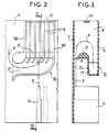
- Figures 2 and 3 respectively show two sections, one in front view and the other in left view of a rack for storage device according to the invention.
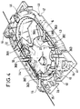
- FIG. 4 presents a perspective view of a cassette for a storage device according to the invention.
- FIG. 1 The storage device presented in FIG. 1 is shown incorporated in a patching box 1, of the wall cabinet type, closed by a door 2 with lateral hinges 3 and lockable using fixing screws 4.
- the patch box 1 receives optical cables 5, here by its base 6, these cables having, in known manner, not developed here, different destinations.
- the optical fibers 8 that these cables 5 comprise are conventionally dissociated from one another in the box 1, in order to be connected together according to the chosen patching arrangements.
- each bracket 10 serves for example as a support for two carrying strands 9 and comprises for this purpose two strand fastenings by screws, in parallel conduits, the screws, directly accessible through the door opening of the box, being offset l on the one hand compared to the other.
- connection between fibers 8 are made by means of connectors 12, here fixed parallel to one of the vertical sides of the box 1 on a support structure 13, these connectors 12 and this structure 13 not being developed here, because they are not directly related to the invention.
- the cassettes 14, of at least roughly parallelepiped shape are here aligned face against face on the floor and along the bottom wall 11 of the box, being fixed so as to be removable, for example by hooking or snap-fastening.
- the same fiber 8 emerges from the cassette through a mouth which opens towards the ceiling of the cabinet when this cassette is in place in the box. It then enters a storage bin 16 which is common to at least some, if not all, of the fibers.
- the rack 16 which is for example made of a molded material, is also detailed in FIGS. 2 and 3, it comprises a plurality of large and thin parallel boxes in each of which fibers each form a reserve loop, one of which from both ends exits through a common passage 0 positioned at one end of the boxes and here under the latter.
- the passage 0 is parallel to a conduit 17 leading to a lateral opening, here flared, which is common at least to several boxes and through which the other end of each of the loops stored in the rack 16 exits.
- the boxes are formed between parallel partitions 18 whose spacing is small, for example ten millimeters for boxes having a length of two hundred and twenty millimeters and a width of one hundred and ten millimeters.
- the partitions 18 are generally parallel to the large faces of the cassettes 14, above at least part of which the rack 16 is placed in the box 1, the ceiling of the rack 16 being formed by, or pressed against , at least part of the ceiling of cabinet 1.
- the opening of the conduit 17 is essentially delimited by the two partitions 18E and 18F, extremes, of the rack 16 - Figure 2-.
- One of these two extreme partitions, 18F which comes here to be pressed against one of the two sides of the box 1, bends, in a first direction, to come to form the floor of the conduit passing under the curved ends, but more short, intermediate partitions 18, then in an opposite direction to form the flared opening in connection with the corresponding end of the other extreme partition 18E.
- the latter is here wound on itself in the first direction indicated above at this corresponding end, the radii of curvature of the ends of the different partitions 18 at the mouth being chosen as a function of the minimum radius of curvature R admissible for fibers 8.
- the flaring of the mouth which is determined by the opposite windings of the ends of the end partitions is placed laterally at one end of the rack 16 which is here located at the bottom of this rack in the box 1. It allows a large variation in orientation , inside the box 1, of the two ends of the fibers, the loops of which are stored in the box 16.
- the sectional view along III-III of Figure 3 shows that the rack 16 is closed by two parallel walls on its front face and on its rear face.
- One of these two walls is for example constituted by the bottom wall 11 of the box 1, while the other is a plate 19, attached and preferably transparent; this plate 19 is located on the side of the door opening in the box 1, it covers the corresponding edge of the various partitions 18, on this side, and it is removable to allow insertion of the loops in the boxes.
- FIG. 3 shows that the duct 17, the bottom of which is formed by the extension of the extreme partition 18F under the other partitions, as described above, only extends over part of the width of the rack 16, being limited by a rim 20 which extends parallel to the plate 19, at approximately at least half the width of the rack, along the length of the conduit 17 and, in height, above the bottom of the intermediate partitions 18, relative to the bottom of the conduit.
- the rim 20 is itself longitudinally bordered by an additional thickness 21 which here is semi-cylindrical and offset laterally towards the bottom wall 11 relative to the rim, when the rack 16 is in place in the box 1.
- This extra thickness 21 runs throughout the rack 16 and serves to secure all the partitions 18, to one another, in association with a longitudinal tab 22 running here at the top of the partitions.
- the extra thickness 21 also has a radius of curvature which is a function of the admissible radius of curvature R for the fibers and it borders the passage 0 which is formed between the bottom wall 11 of the box when the rack 16 is in place and itself , as seen in Figure 3.
- the orientation of a fiber 8 to be connected to one of the connectors 12 can vary widely, without drawback, at the outlet of the rack 16, via the conduit 17.
- cassettes 14 are associated with the rack 16, being placed at a lower level of the box 1 relative to the latter.
- cassettes 14 conventionally make it possible to store additional reserves of fibers 8, in particular downstream of the cable glands 7 when the fibers are recovered at this level, in the box 1.
- FIG. 4 An example of such a cassette 14 is presented in FIG. 4, it makes it possible to have two storage housings intended to each receive a portion of at least one optical fiber, the two ends of which exit from the cassette.
- the cassette is provided with a separation structure which is here a median wall 32, on either side of which the two storage housings are formed. It is also possible to produce this separation structure in the form of an openwork frame, not shown, on either side of which the two storage housings are arranged.
- each of these two housings is in the form of an at least roughly annular-looking duct formed between an element 33, called the minimum loop winding limit, and a peripheral edge 34, l one and the other projecting on either side of the partition wall 32.
- the limiting element 33 is here constituted by a cylindrical structure which extends on either side of the partition wall with which it is here molded in a single block.
- the limiting element 33 is also capable of being produced in a different way, for example in the form of a plurality of studs arranged at least roughly circularly on either side of the partition wall 32, from the moment or it limits, to a predetermined minimum value, the reduction of a loop of fiber which comes to grip it, when the fiber is pulled towards the outside of the housing where it is coiled; this predetermined value corresponding by example with the minimum admissible radius of curvature for the fibers to be used.
- teeth 36 are here parallel to the partition wall 32 at a level which corresponds to the level of projection of the cylindrical structure on either side of the partition wall.
- Each tooth partially closes one of the conduits which it overhangs between the peripheral edge 34 from which they originate and the limiting element 33, so as to prevent a lateral exit of a fiber from this conduit.
- peripheral grooves 37 are formed in the cylindrical structure of the limiting element 33 facing the free ends of the teeth 36 which are partially introduced therein.
- each tooth 6 is associated with a cutout 38 of the same shape which is parallel to it in the separation wall, such as 38A, 38B, 38C, 38D to 36A, 36B, 36C and 36D.
- a fiber passage is made to make the two housings of a cassette communicate, it is here constituted by a slot 39 formed in the partition wall 32 flush with the cylindrical structure of the limiting element 33 on one side where this structure is offset longitudinally towards the peripheral edge so that the conduits are of narrower width at this level than the other where the possibilities of deployment of the fiber are increased by the significant widening of the conduit in each housing.
- the slot 39 extends over one of the possible fiber paths along the limit element 33, it ensures immobilization by wedging each fiber relative to to the cassette which makes it possible to have two reserves of fibers, in the housings, on either side of the slot for the two parts of each fiber which are located on either side of this slot.
- a slot 40 is formed in the partition wall 32, it ends transversely in the middle part of the slot 39 and opens onto the outside of the cassette to allow the introduction of a fiber transversely into the slot 39 from the outside.
- the fibers 8 are immobilized at the level of the slot 39, for example by lining the fibers with stop collars, not shown, which come to grip them and which cannot pass through the slot 39 because of their dimensions or by a clamping collar 45 fixing them to the element 33.
- Elements 46 forming a cover and here transparent, are placed on either side of the cassette to complete the obturation of the conduits in addition to the teeth, in particular at the widest part of the conduits to prevent a part fiber stored in the housings does not exit laterally out of the cassette outside the mouths 41, 42, 43 provided for this purpose.
- the mouths 41, 42 are here formed in the peripheral border 34, each for a different housing, at a different end of the cassette on either side of the partition wall 32, flush with which they are located and along from which they open, possibly by several openings as can be seen on the right-hand side of FIG. 4 for the mouth 41.
- the mouth 43 is here constituted by a single opening formed in the peripheral border on the same side of the partition wall 32 as the mouth 41 and laterally, between the two ends where the mouths 41, 42 open and on the side opposite to that which carries hooks 44 for fixing the cassette to the box 1.
- a fiber 8 into a cassette is preferably carried out by pushing the fiber between the free ends of the teeth 36 and the cylindrical structure of the limiting element 33, at the level of the peripheral grooves 37.
- This fiber 8 then preferably forms a single loop in each housing by entering it for example through the mouth 43 and emerging through the mouth 42 after having passed through the partition wall 32 through the slots 39, 40.
- Each fiber loop 1 is capable of taking a maximum extension in the duct of a housing which contains it, it then runs along the peripheral edge 34 and then makes it possible to obtain a maximum reserve for the part of fiber which comprises it.
- a pull, from the outside of the cassette, on this part of fiber then makes it possible to extract the portion in reserve through the mouth it crosses, the extension of the corresponding loop reducing until the moment when this loop is pressed against the limit element 33.
- the reintroduction of a portion of extracted fiber is provided to be achievable by simple pushing on the fiber in the direction of reintroduction through the mouth from which it comes out.
- This reintroduction is intended to be carried out by itself taking advantage of the relative rigidity of the fiber, in particular when the latter is moreover fixed relative to a location which the cassette is brought closer to, as happens in the case cassettes 14 in the box 1, when a cassette is replaced after being extracted. Likewise, the extraction of the fibers by pulling and the reinsertion by pushing are provided with the rack 16.
Landscapes
- Physics & Mathematics (AREA)
- General Physics & Mathematics (AREA)
- Optics & Photonics (AREA)
- Light Guides In General And Applications Therefor (AREA)
- Mechanical Coupling Of Light Guides (AREA)
Claims (4)
- Einrichtung zum Lagern von Lichtleitfasern in Form einer Reserveschleife einer an jeder der Fasern vorgesehenen Überlänge und zur Ermöglichung der freien Entnahme eines Teils der gelagerten Überlänge und der freien Wiedereinführung eines nicht mehr benötigten entnommenen Teils in die Schleife, dadurch gekennzeichnet, daß die Einrichtung aus einem Lagergehäuse von im wesentlichen parallelepipedischer Form besteht, das bei senkrechter Lage des Gehäuses aufweist:- zwei einander gegenüberliegende, senkrechte, als hintere Wand (11) und vordere Wand (19) bezeichnete Hauptwände,- eine Gruppe von senkrechten Zwischenwänden (18), die je von der hinteren Wand zur vorderen Wand reichen und die zwischen sich und der hinteren und der vorderen Wand eine Reihe von Fächern bilden, die je für die Reserveschleife einer der Fasern (8) bestimmt sind, und- einen waagrechten Träger (21), der sich in einem unteren Abschnitt des Gehäuses zwischen der hinteren und der vorderen Wand erstreckt, ohne jedoch an die eine und die andere dieser Wände anzustoßen, und auf der die verschiedenen Zwischenwände befestigt sind, wobei der Träger ein in das Innere der Fächer gewölbtes halbzylindrisches Profil besitzt und einerseits zwischen sich, der hinteren Wand und den Zwischenwänden erste individuelle Eingänge (O) für Fasern zu den verschiedenen Fächern, und andererseits zwischen sich, der vorderen Wand und den Zwischenwänden zweite individuelle Eingänge für Fasern zu den verschiedenen Fächern begrenzt, wobei die vordere Wand abnehmbar ist, derart, daß der Zugang zu den Fächern an der Vorderseite des Gehäuses zum anfänglichen Einschieben der Reserveschleife in jedes der Fächer ermöglicht wird.
- Einrichtung nach Anspruch 1, dadurch gekennzeichnet, daß eine erste Abschlußwand (18F) der Gruppe der Zwischenwände einen nur vorne vorhandenen unteren Endabschnitt besitzt, der sich durch einen gebogenen Abschnitt vom Ende des waagrechten Trägers, an dem die erste Abschlußwand befestigt ist, über einen im wesentlichen bis in Höhe der zweiten Abschlußwand (18E) der Gruppe der Zwischenwände waagrechten Abschnitt unter Bildung eines Kanalbodens (17) unter den zweiten Eingängen der Fächer erstreckt, und daß der waagrechte Träger (21) einen senkrechten Kragen (20) besitzt, der unter dem Träger entlang von dessen vorderer Kante vorspringt und an der entsprechenden hinteren Kante des Bodens anschließt und mit der vorderen Wand Wände des Kanals definiert, indem sie diesen zu beiden Seiten des Bodens begrenzen.
- Einrichtung nach Anspruch 2, dadurch gekennzeichnet, daß der Kanal im wesentlichen in Höhe der zweiten Abschlußwand (18E) in einer mindestens teilweise erweiterten Mündung endet, die durch eine Krümmung des Endabschnitts des Bodens definiert wird.
- Einrichtung nach Anspruch 2 oder 3, dadurch gekennzeichnet, daß die anderen Zwischenwände mit Ausnahme der ersten Abschlußwand jeweils einen unteren, vorderen Endabschnitt besitzen, der im wesentlichen parallel zum gekrümmten Abschnitt der ersten Abschlußwand gekrümmt ist und so im wesentlichen in den Kanal (17) oberhalb des Bodens hineinragt.
Applications Claiming Priority (2)
| Application Number | Priority Date | Filing Date | Title |
|---|---|---|---|
| FR8916814 | 1989-12-19 | ||
| FR8916814A FR2656114B1 (fr) | 1989-12-19 | 1989-12-19 | Dispositif de stockage de fibres optiques, notamment pour coffret de brassage. |
Publications (2)
| Publication Number | Publication Date |
|---|---|
| EP0434530A1 EP0434530A1 (de) | 1991-06-26 |
| EP0434530B1 true EP0434530B1 (de) | 1994-05-18 |
Family
ID=9388695
Family Applications (1)
| Application Number | Title | Priority Date | Filing Date |
|---|---|---|---|
| EP90403608A Expired - Lifetime EP0434530B1 (de) | 1989-12-19 | 1990-12-14 | Speichervorrichtung für Lichtwellenleiter in einem Verteilerschrank |
Country Status (4)
| Country | Link |
|---|---|
| EP (1) | EP0434530B1 (de) |
| DE (1) | DE69009027T2 (de) |
| ES (1) | ES2055890T3 (de) |
| FR (1) | FR2656114B1 (de) |
Families Citing this family (7)
| Publication number | Priority date | Publication date | Assignee | Title |
|---|---|---|---|---|
| FR2687801B1 (fr) * | 1992-02-21 | 1997-01-03 | Mars Actel | Cassette de fibres optiques. |
| GB9318602D0 (en) * | 1993-09-08 | 1993-10-27 | Raychem Sa Nv | Optical fibre organizer |
| GB9405814D0 (en) * | 1994-03-24 | 1994-05-11 | Augat Limited | Management of optical fibres |
| US5530954A (en) * | 1995-01-13 | 1996-06-25 | Telect, Inc. | Telecommunication fiber optic patch panel shelf assembly |
| US5535298A (en) * | 1995-01-30 | 1996-07-09 | The Whitaker Corporation | Pedestal for fiber optic cable |
| FR2733843B1 (fr) * | 1995-05-03 | 1997-05-30 | Alcatel Submarcom | Dispositif organiseur de connexion de cables a fibres optiques et boite de jonction de cables optiques |
| CN105093451B (zh) * | 2015-07-24 | 2018-10-30 | 华为技术有限公司 | 一种分纤及配电装置及通信站点 |
Family Cites Families (4)
| Publication number | Priority date | Publication date | Assignee | Title |
|---|---|---|---|---|
| DE530625C (de) * | 1927-05-17 | 1931-07-30 | Julius Baggesen | Vorrichtung zur Abhaltung von Erschuetterungen, die vom Strassenbetrieb herruehren, an Gebaeuden |
| DE3530625A1 (de) * | 1985-08-28 | 1987-03-05 | Rose Walter Gmbh & Co Kg | Verteilergehaeuse fuer die aufnahme von kabelspleissen bei lichtwellenleitern |
| US4898448A (en) * | 1988-05-02 | 1990-02-06 | Gte Products Corporation | Fiber distribution panel |
| DE8809714U1 (de) * | 1988-07-29 | 1988-09-22 | Siemens AG, 1000 Berlin und 8000 München | Verteiler für Telekommunikationsanlagen mit Lichtleitern |
-
1989
- 1989-12-19 FR FR8916814A patent/FR2656114B1/fr not_active Expired - Lifetime
-
1990
- 1990-12-14 DE DE69009027T patent/DE69009027T2/de not_active Expired - Fee Related
- 1990-12-14 ES ES90403608T patent/ES2055890T3/es not_active Expired - Lifetime
- 1990-12-14 EP EP90403608A patent/EP0434530B1/de not_active Expired - Lifetime
Also Published As
| Publication number | Publication date |
|---|---|
| FR2656114B1 (fr) | 1992-02-28 |
| DE69009027T2 (de) | 1994-09-01 |
| EP0434530A1 (de) | 1991-06-26 |
| DE69009027D1 (de) | 1994-06-23 |
| ES2055890T3 (es) | 1994-09-01 |
| FR2656114A1 (fr) | 1991-06-21 |
Similar Documents
| Publication | Publication Date | Title |
|---|---|---|
| EP0479226B1 (de) | Kassette für optische Verbindungen | |
| EP0185923B1 (de) | Träger für optische Faserverbindungen | |
| EP0538164B1 (de) | Verteilergestell für optische Kabel hoher Kapazität | |
| EP1315009B1 (de) | Anordnung zur Verteilung und Verbindung optischer Fasern für ein optisches Querverbindungssystem | |
| FR2660077A1 (fr) | Boitier de raccordement pour fibres optiques. | |
| EP0348278A1 (de) | Verteil- und Verbindungsvorrichtung für optische Fasern | |
| EP0116480A1 (de) | Gehäuse zum Verbinden und Mischen optischer Fasern | |
| JPH07198961A (ja) | 光ファイバ収容装置及び組立構造 | |
| EP2497730A1 (de) | Vorrichtung zur Akkumulation eines flachen Produkts auf einem flexiblen Band | |
| EP0434530A1 (de) | Speichervorrichtung für Lichtwellenleiter in einem Verteilerschrank | |
| US5341451A (en) | Arrangement for depositing splicing cassettes for light waveguides within a cable sleeve | |
| FR2733843A1 (fr) | Dispositif organiseur de connexion de cables a fibres optiques et boite de jonction de cables optiques | |
| FR2523352A1 (fr) | Cassette de bande magnetique et systeme comportant une telle cassette | |
| EP2156229B1 (de) | Verteilerkasten für glasfasern mit dichtungsmitteln | |
| EP0645657B1 (de) | Vorrichtung zum Verbinden optischer Fasern | |
| FR2656113A1 (fr) | Agencement de stockage de fibres optiques, notamment pour coffret de raccordement. | |
| JPS62163003A (ja) | ガラスフアイバケ−ブルのフアイバ貯蔵装置 | |
| FR2647029A1 (fr) | Filtre a air avec une cartouche filtrante en forme de plaque | |
| WO2016193483A1 (fr) | Cassette de lovage de fibre optique, appareil et procede mettant en oeuvre une telle cassette | |
| EP2156228B1 (de) | Anschlussdose für optische fasern | |
| WO2023131672A1 (fr) | Boite de transfert d'articles dans un carton | |
| FR2566756A1 (fr) | Boite de lovage pour cable | |
| EP0842445A1 (de) | Glasfaser verbindungskassette | |
| EP2156231B1 (de) | Anschlusskasten für optische fasern | |
| FR2917181A1 (fr) | Support d'epissures pour fibres optiques. |
Legal Events
| Date | Code | Title | Description |
|---|---|---|---|
| PUAI | Public reference made under article 153(3) epc to a published international application that has entered the european phase |
Free format text: ORIGINAL CODE: 0009012 |
|
| AK | Designated contracting states |
Kind code of ref document: A1 Designated state(s): DE ES FR GB IT SE |
|
| 17P | Request for examination filed |
Effective date: 19911218 |
|
| 17Q | First examination report despatched |
Effective date: 19920119 |
|
| GRAA | (expected) grant |
Free format text: ORIGINAL CODE: 0009210 |
|
| AK | Designated contracting states |
Kind code of ref document: B1 Designated state(s): DE ES FR GB IT SE |
|
| GBT | Gb: translation of ep patent filed (gb section 77(6)(a)/1977) |
Effective date: 19940516 |
|
| REF | Corresponds to: |
Ref document number: 69009027 Country of ref document: DE Date of ref document: 19940623 |
|
| ITF | It: translation for a ep patent filed | ||
| REG | Reference to a national code |
Ref country code: ES Ref legal event code: FG2A Ref document number: 2055890 Country of ref document: ES Kind code of ref document: T3 |
|
| EAL | Se: european patent in force in sweden |
Ref document number: 90403608.4 |
|
| PLBE | No opposition filed within time limit |
Free format text: ORIGINAL CODE: 0009261 |
|
| STAA | Information on the status of an ep patent application or granted ep patent |
Free format text: STATUS: NO OPPOSITION FILED WITHIN TIME LIMIT |
|
| 26N | No opposition filed | ||
| PGFP | Annual fee paid to national office [announced via postgrant information from national office to epo] |
Ref country code: ES Payment date: 19950906 Year of fee payment: 6 |
|
| PGFP | Annual fee paid to national office [announced via postgrant information from national office to epo] |
Ref country code: SE Payment date: 19960812 Year of fee payment: 7 |
|
| PGFP | Annual fee paid to national office [announced via postgrant information from national office to epo] |
Ref country code: DE Payment date: 19960814 Year of fee payment: 7 |
|
| PGFP | Annual fee paid to national office [announced via postgrant information from national office to epo] |
Ref country code: FR Payment date: 19960912 Year of fee payment: 7 |
|
| PGFP | Annual fee paid to national office [announced via postgrant information from national office to epo] |
Ref country code: GB Payment date: 19961011 Year of fee payment: 7 |
|
| PG25 | Lapsed in a contracting state [announced via postgrant information from national office to epo] |
Ref country code: ES Free format text: LAPSE BECAUSE OF THE APPLICANT RENOUNCES Effective date: 19961216 |
|
| PG25 | Lapsed in a contracting state [announced via postgrant information from national office to epo] |
Ref country code: GB Free format text: LAPSE BECAUSE OF NON-PAYMENT OF DUE FEES Effective date: 19971214 |
|
| PG25 | Lapsed in a contracting state [announced via postgrant information from national office to epo] |
Ref country code: SE Free format text: LAPSE BECAUSE OF NON-PAYMENT OF DUE FEES Effective date: 19971215 |
|
| PG25 | Lapsed in a contracting state [announced via postgrant information from national office to epo] |
Ref country code: FR Free format text: THE PATENT HAS BEEN ANNULLED BY A DECISION OF A NATIONAL AUTHORITY Effective date: 19971231 |
|
| GBPC | Gb: european patent ceased through non-payment of renewal fee |
Effective date: 19971214 |
|
| PG25 | Lapsed in a contracting state [announced via postgrant information from national office to epo] |
Ref country code: DE Free format text: LAPSE BECAUSE OF NON-PAYMENT OF DUE FEES Effective date: 19980901 |
|
| EUG | Se: european patent has lapsed |
Ref document number: 90403608.4 |
|
| REG | Reference to a national code |
Ref country code: FR Ref legal event code: ST |
|
| REG | Reference to a national code |
Ref country code: ES Ref legal event code: FD2A Effective date: 20010402 |
|
| PG25 | Lapsed in a contracting state [announced via postgrant information from national office to epo] |
Ref country code: IT Free format text: LAPSE BECAUSE OF NON-PAYMENT OF DUE FEES;WARNING: LAPSES OF ITALIAN PATENTS WITH EFFECTIVE DATE BEFORE 2007 MAY HAVE OCCURRED AT ANY TIME BEFORE 2007. THE CORRECT EFFECTIVE DATE MAY BE DIFFERENT FROM THE ONE RECORDED. Effective date: 20051214 |