EP0434076B1 - Insert for a shoe - Google Patents
Insert for a shoe Download PDFInfo
- Publication number
- EP0434076B1 EP0434076B1 EP90125039A EP90125039A EP0434076B1 EP 0434076 B1 EP0434076 B1 EP 0434076B1 EP 90125039 A EP90125039 A EP 90125039A EP 90125039 A EP90125039 A EP 90125039A EP 0434076 B1 EP0434076 B1 EP 0434076B1
- Authority
- EP
- European Patent Office
- Prior art keywords
- insert
- insert according
- foot
- region
- sole
- Prior art date
- Legal status (The legal status is an assumption and is not a legal conclusion. Google has not performed a legal analysis and makes no representation as to the accuracy of the status listed.)
- Expired - Lifetime
Links
Images


Classifications
-
- A—HUMAN NECESSITIES
- A43—FOOTWEAR
- A43B—CHARACTERISTIC FEATURES OF FOOTWEAR; PARTS OF FOOTWEAR
- A43B13/00—Soles; Sole-and-heel integral units
- A43B13/14—Soles; Sole-and-heel integral units characterised by the constructive form
- A43B13/141—Soles; Sole-and-heel integral units characterised by the constructive form with a part of the sole being flexible, e.g. permitting articulation or torsion
-
- A—HUMAN NECESSITIES
- A43—FOOTWEAR
- A43B—CHARACTERISTIC FEATURES OF FOOTWEAR; PARTS OF FOOTWEAR
- A43B13/00—Soles; Sole-and-heel integral units
- A43B13/38—Built-in insoles joined to uppers during the manufacturing process, e.g. structural insoles; Insoles glued to shoes during the manufacturing process
-
- A—HUMAN NECESSITIES
- A43—FOOTWEAR
- A43B—CHARACTERISTIC FEATURES OF FOOTWEAR; PARTS OF FOOTWEAR
- A43B17/00—Insoles for insertion, e.g. footbeds or inlays, for attachment to the shoe after the upper has been joined
Definitions
- the invention relates to an insert for a shoe according to the preamble of claim 1.
- an insert for a shoe according to the preamble of claim 1.
- Such an insert is known from German utility model DE-U-88 15 448, which corresponds to the subsequently published EP 0 373 336 A1, and consists of hard, resilient Plate material, preferably of uniform thickness, which has a transverse profile running transversely to the longitudinal direction of the sole, the insert extending over the entire extent of the sole of the foot.
- This insert is suitable for a wide variety of shoes, such as street shoes, sports shoes, boots, sandals, sandals, sneakers or the like.
- the insert and sole according to the present invention can, moreover, optionally have all the features of the insert and sole of the layer-forming document, unless these features are excluded by the present inventive features in the respective embodiment of the present invention, and for this purpose the entire content the generic document and the above-mentioned corresponding European patent application made by this reference with the disclosure content of the present documents.
- the object of the present invention is, in particular, to design an insert and a shoe provided with an insert of the above type in such a way that the biomechanical and physical laws are not significantly impaired by the walk or walked with shoes and, moreover, their support is preferably even supported and promoted , so that it is preferred to make available an insert which corresponds to a great extent to these biomechanical and physical laws and which, when used as a sole, results in shoes which, in accordance with the respective practical provision, result in the best possible effect of these laws in practice.
- the task of a shoe is to guide the foot, to support it, to cushion the impact and to serve the foot as a tool. These tasks are very diverse and cannot be optimally performed by a shoe. This can be seen from the fact that a large number of shoes are designed for special areas of application. There are mountain shoes, indoor sports shoes, tennis shoes, javelin shoes, ski shoes, boxing shoes, soccer shoes, golf shoes and many more.
- a hard insert or insole which preferably consists of metal, in particular spring steel.
- This insert or insole is designed in such a way that it has transverse profiles transverse to the longitudinal direction of the foot, which make this insert or insole movable in the longitudinal direction, still give it a certain amount of torsional freedom, but keep it largely stable in the transverse direction.
- This insole or insole shows many advantages, but it does not or does not take sufficient account of many peculiarities of the biomechanical laws, especially the sport-specific loads.
- the object of the present invention is therefore, in particular, to provide an insert and its use as a sole which is designed in special areas in such a way that sports-specific and / or foot-appropriate loads are made possible which the insert or sole proposed in the prior art does not enables.
- This object is solved by the features of claim 1.
- transverse profile extends essentially or approximately perpendicular to the line of the force application points or comprises several areas of different inclination to the longitudinal axis of the insert.
- the amortization phase which is the phase in which the foot stands on the floor while running, at the moment of the dynamic running movement.
- the line of force application points winds from the point of impact over the center of the heel in the area of the outer edge of the foot, from there to the center of the ball and from there to the big toe or the second toe.
- the line of the force application points is changed and the foot is brought into a constrained position by a relatively rigid, generic insert, in particular made of spring steel, with flat corrugations or other profiles.
- the relevant development of the insert proposed according to the species should be designed according to the invention in such a way that the profiling of the insert runs perpendicularly or approximately perpendicularly to the line of the force application points and not perpendicularly to the longitudinal axis of the sole.
- This profiling may run along the line of the gravity plummet, but must run approximately across the line of the force application points, because then the ground reaction forces can be most safely transferred to the foot or from the foot to the floor. This in turn should have an accelerating effect on the runner's foot.
- the insert according to the invention can be used as an insole or as part of an insole; or as an insole or as part of an insole; or used as a sole reinforcement connected to a sole.
- FIG. 1 shows an insert 1, which consists of a central, longitudinal core 2 which, in accordance with the insert proposed in EP 0 373 336, has a meandering transverse profile.
- 1 shows the course of the line of the force application points and the profiling directions approximately perpendicular to the course of the line of the force application points 22.
- Lips 3 (FIG. 2) can be provided on this central core 2 or longitudinal element, which go to the outer edge of the foot and which do not be more involved in the wavy structure, but run smoothly.
- the lips 3 can have different lengths and different widths, namely in accordance with a locally different damping behavior, as is required.
- the lips 3 are through recesses 6 formed in the profiling of the insert 1 and in this insert form distributed over the entire length of the insert both on the inside and on the outside.
- FIG. 2 shows an oblique view of part of the insert 1 of FIG. 1, the material preferably consisting of spring steel and the lips 3 being flat in the present case.
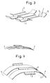
- FIG. 3 shows a section of the insert 1 of FIG. 1, the meandering configuration of the main piece 2 of the binary layer 1 being recognizable.
- the lips or plates 3 are bent upwards in the region of their ends 16.
- FIG. 4 also shows a partial section of the insert 1 with the core piece 2.
- the lips 3 are bent downward in the end region 17 and produce a groove which is open at the bottom, whereby a trampoline effect is brought about under axial load. It is different from shoe to shoe specificity whether the plates or lips 3 come to rest on the upper or lower part of the meander.
- FIG. 5 shows a two-part insert, consisting of the forefoot part 18 and the rear foot part 19, which are independent of one another and are connected to one another by means of a torsion element 20, namely on riveted plates 21. No other detailed embodiment of the insert is shown.
- FIG. 6 shows a toe cap 33 riveted onto the insert 1 (not shown in more detail) in a top view and an oblique view.
- FIG. 7 shows the rear foot area of a meandering profiled insert 1 made of spring steel.
- a steel spring element 39 projects into the interior of the shoe and is fixed on the outside with a rivet 34 on the insert 1.
- a damping element can be accommodated in the intermediate space 40.
- the insert 1 from FIG. 1, which is also shown in FIG. 2, is preferably foamed or installed in a shoe sole.
- the gaps created by the profiling are preferably foamed or provided with other material.
- the lips 3 can then bend upwards under load and then take with them the sole material and shaft material which is located on the outside of the foot. Thanks to their bending, they allow better contact between the outside or inside of the foot and the floor when there is a corresponding load. Due to the different design of the plates or lips 3 in terms of their length and width, the warping behavior can be designed differently depending on the sport.
- the hard, resilient plate material from which the insert 1 according to the invention is made can be metal and / or plastic plate material, preferably steel sheet, particularly preferably spring steel sheet. Furthermore, the hard, resilient plate material preferably has a thickness between 0.1 and 1.5 mm, particularly preferably between 0.3 and 0.5 mm.
- the transverse profiling which is not shown in all the figures of the drawing for reasons of the simplified illustration, but, unless stated otherwise, extends over the entire insert, can have grooves, grooves, ribs, grooves, waves, in cross-section. , be corrugated or beaded, preferably meandering, trapezoidal, zigzag or meandering.
- the width of the periodically repeating cross-section elements is preferably 3 mm to 20 mm, more preferably 6 mm to 16 mm, particularly preferably 8 mm to 13 mm.
Abstract
Description
Die Erfindung betrifft eine einlage für einen Schuh, gemäß dem Oberbegriff des Anspruchs 1. Eine solche Einlage ist aus dem deutschen Gebrauchsmuster DE-U-88 15 448 bekannt, das mit der nachveröffentlichten EP 0 373 336 A1 korrespondiert, und besteht aus hartem, federndem Plattenmaterial von vorzugsweise gleichförmiger Dicke, die eine quer zur Sohlenlängsrichtung verlaufende Querprofilierung aufweist, wobei sich die Einlage über die gesamte Fußsohlenausdehnung erstreckt. Diese Einlage ist für die unterschiedlichsten Schuhe, wie Straßenschuhe, Sportschuhe, Stiefel, Sandalen, Sandaletten, Turnschuhe o. dgl. geeignet.The invention relates to an insert for a shoe according to the preamble of claim 1. Such an insert is known from German utility model DE-U-88 15 448, which corresponds to the subsequently published EP 0 373 336 A1, and consists of hard, resilient Plate material, preferably of uniform thickness, which has a transverse profile running transversely to the longitudinal direction of the sole, the insert extending over the entire extent of the sole of the foot. This insert is suitable for a wide variety of shoes, such as street shoes, sports shoes, boots, sandals, sandals, sneakers or the like.
Die Einlage und Sohle nach der vorliegenden Erfindung kann im übrigen wahlweise alle Merkmale der Einlage und Sohle der gatungsbildenden Druckschrift haben, sofern diese Merkmale nicht durch die vorliegenden erfindungsgemäßen Merkmale in der jeweiligen Ausgestaltung der vorliegenden Erfindung ausgeschlossen werden, und zu diesem Zweck wird der gesamte Inhalt der gattungsbildenden Druckschrift und der obengenannten korrespondierenden europäischen Patentanmeldung durch diese Bezugnahme mit zum Offenbarungsinhalt der vorliegenden Unterlagen gemacht.The insert and sole according to the present invention can, moreover, optionally have all the features of the insert and sole of the layer-forming document, unless these features are excluded by the present inventive features in the respective embodiment of the present invention, and for this purpose the entire content the generic document and the above-mentioned corresponding European patent application made by this reference with the disclosure content of the present documents.
Aufgabe der vorliegenden Erfindung ist es insbesondere, eine Einlage und einen mit einer Einlage der vorstehenden Art versehenen Schuh derart auszugestalten, daß die biomechanischen und physikalischen Gesetze durch den beschuhten Gang oder Lauf nicht wesentlich beeinträchtigt werden und darüberhinaus vorzugsweise in ihrer Auswirkung sogar unterstützt und gefördert werden, so daß bevorzugt eine diesen biomechanischen und physikalischen Gesetzen in hohem Maße entsprechende Einlage zur Verfügung gestellt wird, die in ihrer Verwendung als Sohle Schuhe ergibt, welche der jeweiligen praktischen Bestimmung entsprechend eine bestmögliche Auswirkung dieser Gesetze in der Praxis ergeben.The object of the present invention is, in particular, to design an insert and a shoe provided with an insert of the above type in such a way that the biomechanical and physical laws are not significantly impaired by the walk or walked with shoes and, moreover, their support is preferably even supported and promoted , so that it is preferred to make available an insert which corresponds to a great extent to these biomechanical and physical laws and which, when used as a sole, results in shoes which, in accordance with the respective practical provision, result in the best possible effect of these laws in practice.
Die Aufgabe eines Schuhs ist es, den Fuß zu führen, zu stützen, den auftreffenden Stoß zu dämpfen und dem Fuß als Werkzeug zu dienen. Diese Aufgaben sind sehr vielfältig und können von einem Schuh nicht optimal erfüllt werden. Dies ist daran zu erkennen, daß eine Vielzahl von Schuhen für spezielle Einsatzbereiche konstruiert werden. So gibt es Bergschuhe, Hallensportschuhe, Tennisschuhe, Speerwerferschuhe, Skischuhe, Boxschuhe, Fußballschuhe, Golfschuhe und viele andere mehr.The task of a shoe is to guide the foot, to support it, to cushion the impact and to serve the foot as a tool. These tasks are very diverse and cannot be optimally performed by a shoe. This can be seen from the fact that a large number of shoes are designed for special areas of application. There are mountain shoes, indoor sports shoes, tennis shoes, javelin shoes, ski shoes, boxing shoes, soccer shoes, golf shoes and many more.
Die Problematik im Schuhdesign und in der Schuhherstellung wurde deutlich bei dem ersten internationalen Symposium über Sportschuhe, welches 1984 in München stattfand. Einzelne Fachdisziplinen haben sich hier mit den biokinetischen und dynamischen Anforderungen bei speziellen Belastungsarten, insbesondere Sportarten, an den Schuh auseinandergesetzt. Die daraus resultierenden Ergebnisse führten zu sportartspezifischen Schuhen, die untereinander teilweise überhaupt nicht vergleichbar sind.The problems in shoe design and shoe manufacturing became clear at the first international symposium on sports shoes, which took place in Munich in 1984. Individual specialist disciplines have dealt with the biokinetic and dynamic requirements for special types of stress, especially sports, on the shoe. The resulting results resulted in sports-specific shoes that are sometimes not comparable at all.
In der gattungsbildenden Druckschrift wird nun eine harte Einlage oder Brandsohle vorgeschlagen, die vorzugsweise aus Metall, insbesondere Federstahl, besteht. Diese Einlage oder Brandsohle ist derart ausgestaltet, daß sie quer zur Längsrichtung des Fußes Querprofilierungen aufweist, die diese Einlage oder Brandsohle in Längsrichtung beweglich machen, ihr noch eine gewisse Torsionsfreiheit geben, sie in Querrichtung aber weitgehend stabil halten. Diese Einlage oder Brandsohle zeigt zwar viele Vorteile, doch berücksichtigt sie viele Eigenarten der biomechanischen Gesetze, insbesondere der sportspezifischen Belastungen nicht oder nicht ausreichend.In the generic document, a hard insert or insole is now proposed, which preferably consists of metal, in particular spring steel. This insert or insole is designed in such a way that it has transverse profiles transverse to the longitudinal direction of the foot, which make this insert or insole movable in the longitudinal direction, still give it a certain amount of torsional freedom, but keep it largely stable in the transverse direction. This insole or insole shows many advantages, but it does not or does not take sufficient account of many peculiarities of the biomechanical laws, especially the sport-specific loads.
Aufgabe der vorliegenden Erfindung ist es daher insbesondere, eine Einlage und deren Verwendung als Sohle zur Verfügung zu stellen, die in speziellen Bereichen derart ausgestaltet ist, daß sportartspezifische und/oder fußgerechte Belastungen ermöglicht werden, welche die im Stand der Technik vorgeschlagene Einlage oder Sohle nicht ermöglicht. Diese Aufgabe wird durch die Merkmale des Anspruchs 1 gelöst.The object of the present invention is therefore, in particular, to provide an insert and its use as a sole which is designed in special areas in such a way that sports-specific and / or foot-appropriate loads are made possible which the insert or sole proposed in the prior art does not enables. This object is solved by the features of claim 1.
Eine Weiterbildung der gattungsbildenden Einlage, insbesondere aus Federstahl, liegt erfindungsgemäß darin, daß die Querprofilierung im wesentlichen oder annähernd senkrecht zur Linie der Kraftangriffspunkte verläuft oder mehrere Bereiche unterschiedlicher Schräge zur Längsachse der Einlage umfaßt. Hierzu sei folgendes erläuternd ausgeführt:A further development of the generic insert, in particular made of spring steel, is according to the invention in that the transverse profile extends essentially or approximately perpendicular to the line of the force application points or comprises several areas of different inclination to the longitudinal axis of the insert. For this purpose, the following is explained:
Beim Laufen auf dem Boden findet entsprechend der Amortisationsphase, das ist die Phase, in der der Fuß auf dem Boden steht während des Laufens, im Moment der dynamischen Laufbewegung eine Bodenreaktionskraft statt. Die Summe der Bodenreaktionskräfte auf einer Linie, die benannt wird "die Linie der Kraftangriffspunkte". Die Linie der Kraftangriffspunkte verläuft geschlängelt vom Auftreffpunkt über den Mittelpunkt der Ferse im Bereich des äußeren Fußrandes, von dort zum Mittelpunkt des Ballens und von dort zur Großzehe oder zur zweiten Zehe. Durch eine relativ starre, gattungsgemäße Einlage, insbesondere aus Federstahl, mit planen Riffelungen oder sonstigen Profilierungen wird die Linie der Kraftangriffspunkte verändert und der Fuß in eine Zwangslage hineingebracht.When running on the floor, a floor reaction force takes place according to the amortization phase, which is the phase in which the foot stands on the floor while running, at the moment of the dynamic running movement. The sum of the ground reaction forces on a line that is named "the line of force application points". The line of force application points winds from the point of impact over the center of the heel in the area of the outer edge of the foot, from there to the center of the ball and from there to the big toe or the second toe. The line of the force application points is changed and the foot is brought into a constrained position by a relatively rigid, generic insert, in particular made of spring steel, with flat corrugations or other profiles.
Die diesbezügliche Weiterbildung der gattungsgemäß vorgeschlagenen Einlage soll dahingehend erfindungsgemäß ausgestaltet sein, daß die Profilierung der Einlage senkrecht oder annähernd senkrecht zur Linie der Kraftangriffspunkte verläuft und nicht senkrecht zur Längsachse der Sohle. Diese Profilierung darf sticht zur Linie des Schwerelots verlaufen, sondern muß annähernd quer zur Linie der Kraftangriffspunkte verlaufen, weil dann die Bodenreaktionskräfte am sichersten auf den Fuß bzw. vom Fuß auf den Boden übertragen werden können. Dies wiederum dürfte eine beschleunigende Wirkung auf den Läuferfuß haben.The relevant development of the insert proposed according to the species should be designed according to the invention in such a way that the profiling of the insert runs perpendicularly or approximately perpendicularly to the line of the force application points and not perpendicularly to the longitudinal axis of the sole. This profiling may run along the line of the gravity plummet, but must run approximately across the line of the force application points, because then the ground reaction forces can be most safely transferred to the foot or from the foot to the floor. This in turn should have an accelerating effect on the runner's foot.
Die erfindungsgemäße Einlage kann als Brandsohle oder als Bestandteil einer Brandsohle; oder als Einlegesohle oder als Bestandteil einer Einlegesohle; oder als fest mit einer Sohle verbundene Sohlenarmierung verwendet werden.The insert according to the invention can be used as an insole or as part of an insole; or as an insole or as part of an insole; or used as a sole reinforcement connected to a sole.
Die vorstehenden sowie weitere Vorteile und Merkmale der Erfindung seien nachfolgend anhand einiger bevorzugter Ausführungsbeispiele der erfindungsgemäßen Einlage unter Bezugnahme auf die Figuren der Zeichnunen näher beschrieben, die erfindungsgemäße Ausgestaltungen zeigen; es zeigen:
- Figur 1
- eine Aufsicht auf eine Einlage nach der Erfindung, die Lefzen aufweist;
Figur 2- eine perspektivische Detailansicht der Profilierung und der Lefzen;
- Figur 3
- nach oben, zum Fuß des Trägers hin vorgebogene Lefzen;
- Figur 4
- nach unten, zum Boden vorgebogene Lefzen;
- Figur 5
- eine zweigeteilte Einlage mit Torsionselement;
- Figur 6
- eine Einlage mit Vorfußkappe; und
- Figur 7
- eine andere Ausgestaltung eines Dämpfungselements an einer Einlage;
- Figure 1
- a plan view of an insert according to the invention, which has lips;
- Figure 2
- a detailed perspective view of the profiling and the lips;
- Figure 3
- lips bent upwards towards the wearer's foot;
- Figure 4
- lips bent down towards the floor;
- Figure 5
- a two-part insert with torsion element;
- Figure 6
- an insert with forefoot cap; and
- Figure 7
- another embodiment of a damping element on an insert;
Die Figur 1 zeigt eine Einlage 1, welche aus einem zentralen, längsverlaufenden Kern 2 besteht, der entsprechend der in EP 0 373 336 vorgeschlagenen Einlage eine mäanderförmige Querprofilierung hat. Die Figur 1 zeigt den Verlauf der Linie der Kraftangriffspunkte sowie die Profilierungsrichtungen annähernd senkrecht zum Verlauf der Linie der Kraftangriffspunkte 22. An diesem zentralen Kern 2 oder Längselement können Lefzen 3 (Fig. 2) vorgesehen sein, die bis zum äußeren Fußrand gehen und die nicht mehr in die wellige Struktur einbezogen werden, sondern die plan laufen. Die Lefzen 3 können unterschiedliche Länge aufweisen und unterschiedliche Breite, und zwar entsprechend einem örtlich unterschiedlichen Dämpfungsverhalten, wie es gefordert wird. Die Lefzen 3 sind durch Aussparungen 6 in der Profilierung der Einlage 1 ausgebildet und bei dieser Einlageform sowohl auf der Innen- wie auf der Außenseite über die gesamte Länge der Einlage verteilt.FIG. 1 shows an insert 1, which consists of a central,
Die Figur 2 zeigt eine Schrägansicht auf einen Teil der Einlage 1 der Figur 1, wobei das Material vorzugsweise aus Federstahl besteht und die Lefzen 3 vorliegend plan sind.FIG. 2 shows an oblique view of part of the insert 1 of FIG. 1, the material preferably consisting of spring steel and the lips 3 being flat in the present case.
Die Figur 3 zeigt einen Ausschnitt aus der Einlage 1 der Figur 1, wobei die mäanderförmige Ausgestaltung des Hauptstücks 2 der Binlage 1 erkennbar ist. Die Lefzen oder Platten 3 sind im Bereich ihrer Enden 16 nach oben ausgebogen.FIG. 3 shows a section of the insert 1 of FIG. 1, the meandering configuration of the
Die Figur 4 zeigt ebenfalls einen Teilsausschnitt der Einlage 1 mit dem Kernstück 2. Die Lefzen 3 sind im Endbereich 17 nach unten gebogen und erzeugen eine nach unten offene Kehlung, wodurch bei axialer Belastung ein Trampolineffekt bewirkt wird. Dabei ist es von Schuh- zu Schuhspezifität unterschiedlich, ob die Platten oder Lefzen 3 am oberen oder unteren Teil des Mäanders zu liegen kommen.FIG. 4 also shows a partial section of the insert 1 with the
Die Figur 5 zeigt eine zweigeteile Einlage, bestehend aus Vorfußpartie 18 und Rückfußpartie 19, die unabhängig voneinander sind und über ein Torsionselement 20 miteinander verbunden sind und zwar an vernieteten Platten 21. Eine sonstige nähere Ausgestaltung der Einlage ist nicht gezeichnet.FIG. 5 shows a two-part insert, consisting of the
Die Figur 6 zeigt eine auf die nicht näher gezeigte Einlage 1 aufgenietete Zehenkappe 33 in Aufsicht und Schrägsicht.FIG. 6 shows a
Die Figur 7 zeigt den Rückfußbereich einer aus Federstahl bestehenden mäanderförmig profilierten Einlage 1. Hier ragt ein Stahlfederelement 39 in den Schuhinnenraum und ist auf der Außenseite mit einem Niet 34 an der Einlage 1 fixiert. Im Zwischenraum 40 kann ein Dämpfungselement untergebracht sein.FIG. 7 shows the rear foot area of a meandering profiled insert 1 made of spring steel. Here a
Die Einlage 1 aus Figur 1, die auch in Figur 2 dargestellt ist, wird vorzugsweise in einer Schuhsohle eingeschäumt oder eingebaut. Die durch die Profilierung entstehenden Zwischenräume werden vorzugsweise ausgeschäumt oder mit anderem Material versehen. Die Lefzen 3 können sich dann bei Belastung nach oben biegen und nehmen dann das dort ansetzende, an der Fußaußenseite liegende Sohlenmaterial und Schaftmaterial mit. Sie ermöglichen durch ihre Verbiegung einen besseren Kontakt zwischen Fußaußen- oder -innenseite und Boden bei entsprechender Belastung. Durch unterschiedliche Ausgestaltung der Platten bzw. Lefzen 3 in ihrer Länge und Breite kann das Verziehungsverhalten sportartspezifisch unterschiedlich gestaltet werden.The insert 1 from FIG. 1, which is also shown in FIG. 2, is preferably foamed or installed in a shoe sole. The gaps created by the profiling are preferably foamed or provided with other material. The lips 3 can then bend upwards under load and then take with them the sole material and shaft material which is located on the outside of the foot. Thanks to their bending, they allow better contact between the outside or inside of the foot and the floor when there is a corresponding load. Due to the different design of the plates or lips 3 in terms of their length and width, the warping behavior can be designed differently depending on the sport.
Abschließend sei darauf hingewiesen, daß das harte, federnde Plattenmaterial, aus dem die erfindungsgemäße Einlage 1 hergestellt ist, Metall- und/oder Kunststoffplattenmaterial, vorzugsweis Stahlblech, besonders bevorzugt Federstahlblech, sein kann. Weiterhin hat das harte, federnde Plattenmaterial vorzugsweise eine Dicke zwischen 0,1 und 1,5 mm, besonders bevorzugt zwischen 0,3 und 0,5 mm.In conclusion, it should be pointed out that the hard, resilient plate material from which the insert 1 according to the invention is made can be metal and / or plastic plate material, preferably steel sheet, particularly preferably spring steel sheet. Furthermore, the hard, resilient plate material preferably has a thickness between 0.1 and 1.5 mm, particularly preferably between 0.3 and 0.5 mm.
Die Querprofilierung, die aus Gründen der vereinfachten Darstellung nicht in allen Figuren der Zeichnung dargestellt ist, sich jedoch, wenn nichts anderes gesagt ist, über die gesamte Einlage erstreckt, kann im Querschnitt rillen-, riefen-, rippen-, rinnen-, wellen-, riffel- oder sickenförmig sein, vorzugsweise mäanderförmig, trapezförmig, zick-zack-förmig oder mäanderähnlich. Die Breite der sich periodisch wiederholenden Querprofilquerschnittselemente beträgt vorzugsweise 3 mm bis 20 mm, noch bevorzugter 6 mm bis 16 mm, besonders bevorzugt 8 mm bis 13 mm. Schließlich ist die erfindungsgemäße Einlage, sofern vorstehend nichts anderes gesagt ist, eine einstückige Einlage von vorzugsweise gleichförmiger Dicke, in welche die Profilierung durch Verformung, beispielsweise Prägen, oder durch ursprüngliche Formung, beispielsweise Spritzgießen eingebracht ist. Die Aussparungen, Schlitze o. dgl. können ebenfalls entweder durch Verformung, beispielsweise Ausstanzen, oder durch ursprüngliche Formung, beispielsweise Aussparen, vorgesehen werden.The transverse profiling, which is not shown in all the figures of the drawing for reasons of the simplified illustration, but, unless stated otherwise, extends over the entire insert, can have grooves, grooves, ribs, grooves, waves, in cross-section. , be corrugated or beaded, preferably meandering, trapezoidal, zigzag or meandering. The width of the periodically repeating cross-section elements is preferably 3 mm to 20 mm, more preferably 6 mm to 16 mm, particularly preferably 8 mm to 13 mm. Finally, the insert according to the invention, if above nothing else is said, a one-piece insert, preferably of uniform thickness, into which the profiling is introduced by deformation, for example embossing, or by original shaping, for example injection molding. The recesses, slots or the like can also be provided either by deformation, for example punching out, or by original shaping, for example recessing.
Claims (12)
- Insert (1) for a shoe, made of hard, resilient sheet material and having a transverse profile extending at right angles to the longitudinal direction of the sole, with the following feature:- the insert (1) extends over the entire extent of the sole of the foot,
characterised by the following additional features:- in the course of walking or running, force-application points arise along a meandering line (22) extending from the point of impact above the midpoint of the heel in the region of the outer edge of the foot, from there to the midpoint of the ball of the foot and from there to the big toe or to the second toe, and- the transverse profile extends substantially perpendicular to the line (22) of the force-application points. - Insert according to Claim 1, characterised in that recesses (6) are present on the outside and/or inside.
- Insert according to one of Claims 1 or 2, characterised in that the insert (1) is provided with a skeletal structure by being recessed in predetermined regions.
- Insert according to one of Claims 1 to 3, characterised in that slots are recessed in the region of the sole.
- Insert according to one of Claims 1 to 4, characterised in that in the region of the heel part (19) of the insert (1) and/or of the forefoot part (18) one or more cushioning elements are incorporated or one or more recesses (40) are provided for receiving cushioning elements.
- Insert according to one of Claims 2 to 5, characterised in that lips (3) extending inwards or outwards in the direction of the profile are formed by the recesses (6).
- Insert according to Claim 6, characterised in that the lips (3) are pre-curved and/or possess a certain initial stress.
- Insert according to one of Claims 2 to 7, characterised in that the width and/or the depth of the recesses (6) are variable and/or the number of recesses (6) on the inside and outside of the foot is variable.
- Insert according to one of Claims 1 to 5, characterised in that the outline of the insert (1) is smaller than the outline of the corresponding insole.
- Insert according to one of Claims 1 to 5, characterised in that the insert (1) consists of two separate elements (18, 19) which are connected to a torsion bar (20) in the region of the shank piece or are firmly connected to one another elsewhere.
- Insert according to one of Claims 1 to 5, characterised in that slots parallel to the direction of the profile and/or slots extending perpendicular to the direction of the profile or transversely elsewhere are provided.
- Insert according to one or more of the preceding claims, characterised in that a hard toe cap (33) is firmly connected to the insert (1).
Applications Claiming Priority (2)
| Application Number | Priority Date | Filing Date | Title |
|---|---|---|---|
| DE3942094 | 1989-12-20 | ||
| DE3942094A DE3942094A1 (en) | 1989-12-20 | 1989-12-20 | INSOLE AND INSOLE FOR A SHOE |
Publications (3)
| Publication Number | Publication Date |
|---|---|
| EP0434076A2 EP0434076A2 (en) | 1991-06-26 |
| EP0434076A3 EP0434076A3 (en) | 1992-01-15 |
| EP0434076B1 true EP0434076B1 (en) | 1997-09-24 |
Family
ID=6395902
Family Applications (1)
| Application Number | Title | Priority Date | Filing Date |
|---|---|---|---|
| EP90125039A Expired - Lifetime EP0434076B1 (en) | 1989-12-20 | 1990-12-20 | Insert for a shoe |
Country Status (3)
| Country | Link |
|---|---|
| EP (1) | EP0434076B1 (en) |
| AT (1) | ATE158480T1 (en) |
| DE (2) | DE3942094A1 (en) |
Cited By (1)
| Publication number | Priority date | Publication date | Assignee | Title |
|---|---|---|---|---|
| EP1602294A1 (en) | 2004-06-02 | 2005-12-07 | Spannrit Schuhkomponenten GmbH | Polyurethane foam innersole and manufacturing method |
Families Citing this family (19)
| Publication number | Priority date | Publication date | Assignee | Title |
|---|---|---|---|---|
| IT1274345B (en) * | 1994-04-12 | 1997-07-17 | Nordica Spa | SOLE STRENGTHENING DEVICE, ESPECIALLY FOR SPORTS FOOTWEAR. |
| WO1996004811A1 (en) * | 1994-08-12 | 1996-02-22 | One Sport, Inc. | Footwear |
| WO1997046125A2 (en) * | 1996-05-30 | 1997-12-11 | Helmut Mayer | Shoe, method of manufacturing it and its use |
| US5915820A (en) * | 1996-08-20 | 1999-06-29 | Adidas A G | Shoe having an internal chassis |
| IT1290354B1 (en) * | 1997-02-07 | 1998-10-22 | Vibram Spa | BIOMECHANICAL SOLE |
| US6779282B2 (en) | 1998-12-23 | 2004-08-24 | Groehninger Frank Friedrich | Insole |
| AU1751099A (en) | 1998-12-23 | 2000-07-31 | Frank Friedrich Grohninger | Shoe insert |
| DE19904744B4 (en) * | 1999-02-05 | 2005-11-10 | Adidas International Marketing B.V. | shoe |
| DE20021700U1 (en) | 2000-12-22 | 2001-03-01 | Heine Goetz | Clothing element |
| DE202005019691U1 (en) * | 2005-12-16 | 2007-04-26 | Bauerfeind Ag | insole |
| KR101345162B1 (en) * | 2007-05-18 | 2013-12-26 | 더 노스 훼이스 어패럴 코오포레이션 | Supporting plate apparatus for shoes |
| DE202008018366U1 (en) | 2008-11-26 | 2013-07-17 | Helmut Mayer Gbr Mbh | insole |
| DE102008059030B4 (en) * | 2008-11-26 | 2014-09-25 | Helmut Mayer Gbr Mbh | insole |
| DE102010049298A1 (en) * | 2010-10-22 | 2012-04-26 | Fa. Mayer Gbr (Vertretungsberechtigte Gesellschafter: Herr Helmut Mayer, 88045 Friedrichshafen) | Safety shoe with protective cap |
| DE102011109274A1 (en) * | 2011-08-03 | 2013-02-07 | Mayer GbR (Vertretungsberechtigter Gesellschafter: Herr Helmut Mayer, 88045 Friedrichshafen) | Sole chassis for shoes |
| DE102012004631A1 (en) * | 2012-03-06 | 2013-09-12 | Mayer GbR (Vertretungsberechtigter Gesellschafter: Herr Helmut Mayer, 88045 Friedrichshafen) | Protective sandal e.g. gymnastic sandal for e.g. gymnastic, has plastic material that is provided with holding lug and/or retaining strap, and curved sole that is embedded in plastic material |
| EP2846655B1 (en) * | 2012-05-09 | 2016-07-06 | Norbert Schmid GmbH & Co. KG | Insole for shoes |
| US9241535B2 (en) | 2013-03-14 | 2016-01-26 | Nike, Inc. | Sole structures and articles incorporating same |
| ITUA20164633A1 (en) * | 2016-06-24 | 2017-12-24 | Diadora Sport S R L | ANTI-PERFORATION LAMINA FOR FOOTWEAR |
Family Cites Families (2)
| Publication number | Priority date | Publication date | Assignee | Title |
|---|---|---|---|---|
| CH246465A (en) * | 1945-10-02 | 1947-01-15 | Soc D Rech Et D Applic Tech | Shoe. |
| NL234894A (en) * | 1958-01-07 |
-
1989
- 1989-12-20 DE DE3942094A patent/DE3942094A1/en not_active Withdrawn
-
1990
- 1990-12-20 DE DE59010763T patent/DE59010763D1/en not_active Expired - Fee Related
- 1990-12-20 AT AT90125039T patent/ATE158480T1/en active
- 1990-12-20 EP EP90125039A patent/EP0434076B1/en not_active Expired - Lifetime
Cited By (1)
| Publication number | Priority date | Publication date | Assignee | Title |
|---|---|---|---|---|
| EP1602294A1 (en) | 2004-06-02 | 2005-12-07 | Spannrit Schuhkomponenten GmbH | Polyurethane foam innersole and manufacturing method |
Also Published As
| Publication number | Publication date |
|---|---|
| ATE158480T1 (en) | 1997-10-15 |
| EP0434076A3 (en) | 1992-01-15 |
| EP0434076A2 (en) | 1991-06-26 |
| DE59010763D1 (en) | 1997-10-30 |
| DE3942094A1 (en) | 1991-06-27 |
Similar Documents
| Publication | Publication Date | Title |
|---|---|---|
| EP0434076B1 (en) | Insert for a shoe | |
| DE19950121C1 (en) | Sports shoe sole has lateral and medial damping elements attached to carrier plate via L-shaped spring elements | |
| DE60027500T2 (en) | shoe | |
| DE102014215897B4 (en) | adistar boost | |
| EP0087104B1 (en) | Sports shoe with an elastic exterior sole of plastics material | |
| EP0185781B1 (en) | Shoe sole of plastic material or rubber | |
| DE19953147B4 (en) | Shock absorber structure for shoe soles | |
| DE102020125150A1 (en) | SOLE CONSTRUCTION FOR A SHOE | |
| CH638962A5 (en) | CROSS-COUNTRY SKI BOOT. | |
| DE102011102849A1 (en) | Shoe brine with tubes | |
| DE3508308A1 (en) | SPORTSHOE | |
| DE3440206A1 (en) | SHOE SOLE ARRANGEMENT | |
| DE112005003570T5 (en) | Shock absorption device for shoe sole | |
| DE3742918A1 (en) | ALPINE SKI SHOE | |
| DE3933717A1 (en) | Ski for downhill skiing - has top bearing layer and bottom multilayer portion with core between | |
| EP1239929B1 (en) | Board-like gliding device, in particular a ski or snowboard | |
| DE102019107402A1 (en) | Midsole construction for a shoe | |
| DE102020202237A1 (en) | Sole comprising individually deflectable reinforcing elements, and shoe with such a sole | |
| DE69621402T3 (en) | Roller skate frame and method for its production | |
| EP4331423A2 (en) | Running shoe sole comprising a soft-elastic midsole | |
| DE3120349A1 (en) | GOLF SHOES | |
| WO2021165444A1 (en) | Sole for a running shoe | |
| DE2927059A1 (en) | SKI SHOE WITH INTEGRATED SKI TIE | |
| DE4229039C2 (en) | Sports shoe, in particular cross-country ski boot with torsion stiffening and flex-softening devices | |
| DE60319631T2 (en) | Sliding device with two walls |
Legal Events
| Date | Code | Title | Description |
|---|---|---|---|
| PUAI | Public reference made under article 153(3) epc to a published international application that has entered the european phase |
Free format text: ORIGINAL CODE: 0009012 |
|
| AK | Designated contracting states |
Kind code of ref document: A2 Designated state(s): AT BE CH DE DK ES FR GB GR IT LI LU NL SE |
|
| RIN1 | Information on inventor provided before grant (corrected) |
Inventor name: MAYER, HELMUT |
|
| PUAL | Search report despatched |
Free format text: ORIGINAL CODE: 0009013 |
|
| AK | Designated contracting states |
Kind code of ref document: A3 Designated state(s): AT BE CH DE DK ES FR GB GR IT LI LU NL SE |
|
| 17P | Request for examination filed |
Effective date: 19920707 |
|
| 17Q | First examination report despatched |
Effective date: 19930914 |
|
| GRAG | Despatch of communication of intention to grant |
Free format text: ORIGINAL CODE: EPIDOS AGRA |
|
| GRAH | Despatch of communication of intention to grant a patent |
Free format text: ORIGINAL CODE: EPIDOS IGRA |
|
| GRAH | Despatch of communication of intention to grant a patent |
Free format text: ORIGINAL CODE: EPIDOS IGRA |
|
| GRAA | (expected) grant |
Free format text: ORIGINAL CODE: 0009210 |
|
| AK | Designated contracting states |
Kind code of ref document: B1 Designated state(s): AT BE CH DE DK ES FR GB GR IT LI LU NL SE |
|
| PG25 | Lapsed in a contracting state [announced via postgrant information from national office to epo] |
Ref country code: IT Free format text: LAPSE BECAUSE OF FAILURE TO SUBMIT A TRANSLATION OF THE DESCRIPTION OR TO PAY THE FEE WITHIN THE PRE;WARNING: LAPSES OF ITALIAN PATENTS WITH EFFECTIVE DATE BEFORE 2007 MAY HAVE OCCURRED AT ANY TIME BEFORE 2007. THE CORRECT EFFECTIVE DATE MAY BE DIFFERENT FROM THE ONE RECORDED.SCRIBED TIME-LIMIT Effective date: 19970924 Ref country code: FR Free format text: LAPSE BECAUSE OF FAILURE TO SUBMIT A TRANSLATION OF THE DESCRIPTION OR TO PAY THE FEE WITHIN THE PRESCRIBED TIME-LIMIT Effective date: 19970924 Ref country code: NL Free format text: LAPSE BECAUSE OF FAILURE TO SUBMIT A TRANSLATION OF THE DESCRIPTION OR TO PAY THE FEE WITHIN THE PRESCRIBED TIME-LIMIT Effective date: 19970924 Ref country code: GR Free format text: LAPSE BECAUSE OF FAILURE TO SUBMIT A TRANSLATION OF THE DESCRIPTION OR TO PAY THE FEE WITHIN THE PRESCRIBED TIME-LIMIT Effective date: 19970924 Ref country code: GB Free format text: LAPSE BECAUSE OF FAILURE TO SUBMIT A TRANSLATION OF THE DESCRIPTION OR TO PAY THE FEE WITHIN THE PRESCRIBED TIME-LIMIT Effective date: 19970924 Ref country code: DK Free format text: LAPSE BECAUSE OF NON-PAYMENT OF DUE FEES Effective date: 19970924 Ref country code: ES Free format text: THE PATENT HAS BEEN ANNULLED BY A DECISION OF A NATIONAL AUTHORITY Effective date: 19970924 |
|
| REF | Corresponds to: |
Ref document number: 158480 Country of ref document: AT Date of ref document: 19971015 Kind code of ref document: T |
|
| REG | Reference to a national code |
Ref country code: CH Ref legal event code: EP |
|
| REF | Corresponds to: |
Ref document number: 59010763 Country of ref document: DE Date of ref document: 19971030 |
|
| PG25 | Lapsed in a contracting state [announced via postgrant information from national office to epo] |
Ref country code: AT Free format text: LAPSE BECAUSE OF NON-PAYMENT OF DUE FEES Effective date: 19971220 Ref country code: LU Free format text: LAPSE BECAUSE OF NON-PAYMENT OF DUE FEES Effective date: 19971220 |
|
| PG25 | Lapsed in a contracting state [announced via postgrant information from national office to epo] |
Ref country code: SE Effective date: 19971224 |
|
| PG25 | Lapsed in a contracting state [announced via postgrant information from national office to epo] |
Ref country code: BE Free format text: LAPSE BECAUSE OF NON-PAYMENT OF DUE FEES Effective date: 19971231 Ref country code: CH Free format text: LAPSE BECAUSE OF NON-PAYMENT OF DUE FEES Effective date: 19971231 Ref country code: LI Free format text: LAPSE BECAUSE OF NON-PAYMENT OF DUE FEES Effective date: 19971231 |
|
| EN | Fr: translation not filed | ||
| NLV1 | Nl: lapsed or annulled due to failure to fulfill the requirements of art. 29p and 29m of the patents act | ||
| GBV | Gb: ep patent (uk) treated as always having been void in accordance with gb section 77(7)/1977 [no translation filed] |
Effective date: 19970924 |
|
| BERE | Be: lapsed |
Owner name: MAYER HELMUT Effective date: 19971231 |
|
| PLBE | No opposition filed within time limit |
Free format text: ORIGINAL CODE: 0009261 |
|
| STAA | Information on the status of an ep patent application or granted ep patent |
Free format text: STATUS: NO OPPOSITION FILED WITHIN TIME LIMIT |
|
| REG | Reference to a national code |
Ref country code: CH Ref legal event code: PL |
|
| 26N | No opposition filed | ||
| PGFP | Annual fee paid to national office [announced via postgrant information from national office to epo] |
Ref country code: DE Payment date: 20061214 Year of fee payment: 17 |
|
| PG25 | Lapsed in a contracting state [announced via postgrant information from national office to epo] |
Ref country code: DE Free format text: LAPSE BECAUSE OF NON-PAYMENT OF DUE FEES Effective date: 20080701 |