EP0433903A1 - Body for a motor vehicle - Google Patents
Body for a motor vehicle Download PDFInfo
- Publication number
- EP0433903A1 EP0433903A1 EP90124158A EP90124158A EP0433903A1 EP 0433903 A1 EP0433903 A1 EP 0433903A1 EP 90124158 A EP90124158 A EP 90124158A EP 90124158 A EP90124158 A EP 90124158A EP 0433903 A1 EP0433903 A1 EP 0433903A1
- Authority
- EP
- European Patent Office
- Prior art keywords
- floor
- fact
- floor pan
- body according
- attachment
- Prior art date
- Legal status (The legal status is an assumption and is not a legal conclusion. Google has not performed a legal analysis and makes no representation as to the accuracy of the status listed.)
- Granted
Links
Images


Classifications
-
- B—PERFORMING OPERATIONS; TRANSPORTING
- B62—LAND VEHICLES FOR TRAVELLING OTHERWISE THAN ON RAILS
- B62D—MOTOR VEHICLES; TRAILERS
- B62D65/00—Designing, manufacturing, e.g. assembling, facilitating disassembly, or structurally modifying motor vehicles or trailers, not otherwise provided for
- B62D65/02—Joining sub-units or components to, or positioning sub-units or components with respect to, body shell or other sub-units or components
- B62D65/04—Joining preassembled modular units composed of sub-units performing diverse functions, e.g. engine and bonnet
-
- B—PERFORMING OPERATIONS; TRANSPORTING
- B62—LAND VEHICLES FOR TRAVELLING OTHERWISE THAN ON RAILS
- B62D—MOTOR VEHICLES; TRAILERS
- B62D25/00—Superstructure or monocoque structure sub-units; Parts or details thereof not otherwise provided for
- B62D25/02—Side panels
- B62D25/025—Side sills thereof
-
- B—PERFORMING OPERATIONS; TRANSPORTING
- B62—LAND VEHICLES FOR TRAVELLING OTHERWISE THAN ON RAILS
- B62D—MOTOR VEHICLES; TRAILERS
- B62D25/00—Superstructure or monocoque structure sub-units; Parts or details thereof not otherwise provided for
- B62D25/08—Front or rear portions
- B62D25/14—Dashboards as superstructure sub-units
-
- B—PERFORMING OPERATIONS; TRANSPORTING
- B62—LAND VEHICLES FOR TRAVELLING OTHERWISE THAN ON RAILS
- B62D—MOTOR VEHICLES; TRAILERS
- B62D25/00—Superstructure or monocoque structure sub-units; Parts or details thereof not otherwise provided for
- B62D25/20—Floors or bottom sub-units
-
- B—PERFORMING OPERATIONS; TRANSPORTING
- B62—LAND VEHICLES FOR TRAVELLING OTHERWISE THAN ON RAILS
- B62D—MOTOR VEHICLES; TRAILERS
- B62D25/00—Superstructure or monocoque structure sub-units; Parts or details thereof not otherwise provided for
- B62D25/20—Floors or bottom sub-units
- B62D25/2009—Floors or bottom sub-units in connection with other superstructure subunits
- B62D25/2036—Floors or bottom sub-units in connection with other superstructure subunits the subunits being side panels, sills or pillars
-
- B—PERFORMING OPERATIONS; TRANSPORTING
- B62—LAND VEHICLES FOR TRAVELLING OTHERWISE THAN ON RAILS
- B62D—MOTOR VEHICLES; TRAILERS
- B62D25/00—Superstructure or monocoque structure sub-units; Parts or details thereof not otherwise provided for
- B62D25/20—Floors or bottom sub-units
- B62D25/2009—Floors or bottom sub-units in connection with other superstructure subunits
- B62D25/2045—Floors or bottom sub-units in connection with other superstructure subunits the subunits being fire walls
-
- B—PERFORMING OPERATIONS; TRANSPORTING
- B62—LAND VEHICLES FOR TRAVELLING OTHERWISE THAN ON RAILS
- B62D—MOTOR VEHICLES; TRAILERS
- B62D29/00—Superstructures, understructures, or sub-units thereof, characterised by the material thereof
- B62D29/04—Superstructures, understructures, or sub-units thereof, characterised by the material thereof predominantly of synthetic material
- B62D29/048—Connections therefor, e.g. joints
Definitions
- the present invention relates to a motor vehicle body of the type comprising a frame suitable for supporting several fixed and movable enclosing panels, and a floor pan defining the bottom of the interior of the vehicle.
- the frame normally comrises two side members, two front supports fixed to the front end of the side members and forming therewith a pre-defined angle, a front cross member suitable for attaching the ends of the supports together, and a rear cross member suitable for attaching the rear ends of the side members together.
- the floor pan is normally fixed to the frame by non-dismountable means of attachment, for example by welding, or is fixed thereto using dismountable means of attachment normally comprising threaded parts.
- a body of this type is difficult to assemble in a fully automated manner using dedicated machines and devices.
- the vehicle can be noisy due to vibration of the said floor pan and the relative parts attached to the frame.
- a body of this type can be excessively costly due to the numerous bending operations of the sheet metal from which both the frame or the floor pan are obtained; since these parts are of steel, the total weight of the body can be particularly high.
- An aim of the present invention is to produce a body for a motor vehicle in which the disadvantages described can be eliminated.
- a body substantially comprising a frame capable of supporting several fixed and mobile enclosing panels and a floor pan defining the bottom of the interior of the vehicle, the said frame comprising two side members, two front supports fixed to the front end of the said side members and forming thereby a pre-defined angle, a front cross member suitable for attaching the ends of the said supports together and a rear cross member suitable for attaching the rear ends of the said side members together, characterised by the fact that the said floor pan is provided with means of attachment suitable for fixing the said floor pan to the lower surface of the said frame and means of attachment suitable for fixing several mechanical parts and assemblies to the said floor pan to form a single unit, prior to the floor pan being fixed to the said frame by the said means of attachment.
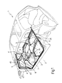
- figure 1 represents a perspective view of the basic elements of the body of the invention
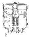
- FIGS 2, 3 and 4 represent plan, section and front views, respectively, of the floor pan of the body
- FIGS 5 and 6 represent sections through the floor pan of figure 2, through planes V-V and VI-VI respectively;
- figure 7 represents a section of a part of the floor pan of figure 2 through plane VII-VII;
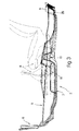
- figure 8 represents a section through a side member of the body frame and a part of the floor pan thereof;
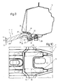
- figure 9 represents a vertical section through the front part of the floor pan to which mechanical parts and assemblies of the motor vehicle are attached;
- figure 10 represents a section through a part of the floor pan suitable for illustrating the attachment of another mechanical assembly to the floor pan;
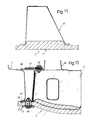
- figure 11 represents a transversal section of a cross member fixed to the floor pan
- figure 12 represents a side view of the cross member of figure 11;
- figure 13 represents a detail, on a larger scale, of figure 12 suitable for illustrating the manner in which the cross member is attached to the side members of the frame;
- FIGS 14 to 16 represent various forms of realisation of the means for attaching mechanical parts and assemblies to the floor pan of the body.
- the body of the invention substantially comprises a frame, indicated as a whole by reference 1 (fig.1), which is capable of supporting several fixed and movable enclosing panels (not shown) and a floor pan 2.
- the frame in turn, comprises two side members 3, two front supports 4 fixed to the front end of the side members and forming thereby a pre-defined angle, a front cross member 5 suitable for attaching the ends of supports 4 together and a rear cross member 6, suitable for attaching the rear ends of the said side members together.
- the floor pan 2 shown in figures 2, 3 and 4, substantially comprises a floor 7 and a fireproof wall 8 forming a pre-defined angle with the former and suitable for dividing the engine compartment from the interior of the vehicle.
- the floor 7 is shaped so as to produce a tunnel 9 and a cross member 10, visible in section in figures 5 and 6.
- the abovementioned floor pan can be constructed of sheet metal, it is preferably constructed by forming a semi-finished piece of plastic material; this comprises several layers of plastic material, at least two of which are external layers 11 (figures 8, 14, 15 and 16) having a higher density and mechanical resistance and at least one intermediate layer 12 with a lower density.
- the floor pan 2 is provided with means of attachment suitable for fixing it to the lower surface of the frame, and with means of attachment suitable for fixing several mechanical parts and assemblies to the floor pan to form thereby a single unit.
- This unit comprises, in addition to the floor pan, a servo-brake device 13 (figure 9), pedals 14, a steering support cradle 15, a steering box 16, two seat support guides 17 (figure 6) and an assembly 18 (figure 3) of which the handbrake and gear levers form a part.
- the means for attaching the floor pan to the frame comprises continuous seating 24 (fig.8) capable of resting against the lower surface 25 of side members 3 and on the lower surface 26 (figure 3) of rear cross member 6; such means of attachment further comprises several metal gussets 27 (figures 2 and 8) each of which is suitable for resting against the lower surface 28 of the floor 7 and for attachment, by threaded organs of attachment 29, to side members 3 and rear cross member 6.
- some gussets 27 are provided, four of which are fixed to the side members and the others to the rear cross member 6 and front fireproof wall.
- each gusset 27 has a concavity 31 suitable for housing the said rim. Furthermore, between the continuous seating 24 and the lower surfaces 25 and 26 respectively of side members 3 and rear cross member 6 is placed a layer of elastic adhesive 32; a similar layer of adhesive 33 is interposed between the rim 30 and the concavity 31. Finally, conveniently, each gusset 27 has a lug 34 suitable for resting against the lower surface 25 of the floor 7, with the interposition of a further layer of elastic adhesive 35.
- the abovementioned means of attachment suitable for fixing the floor pan 2 to the frame 1 further comprises a layer of adhesive 40 (figure 1) placed between the edges of the fireproof wall 8 and the lower surfaces of the supporting elements 4 and front cross member 5.
- the floor pan 2 being constructed of a plastic material according to the aforementioned manner, may also comprise cross member 10 (fig.2), which is produced directly from the material of the floor 7, a separate cross member 41 (figures 11 and 12) constructed of sheet metal and having a substantially U-shaped section, as can be seen in figure 11; this cross member is fixed, in the manner indicated, to the side members 3 and is suitable for supporting seat guides 42 (figure 12).
- Each end of the said cross member is attached to a corresponding side member 3 by means of attachment shown in figure 13; it comprises substantially a seating 43 obtained on the outer edge of the floor 7 and suitable for resting against the lower surface 44 of a corresponding side member, at least one bolt 46 suitable for attaching the said edge to the side member and a lug 47 capable of being supported on the upper surface 48 of the said side member and of being fixed, by at least one other bolt 49, to the end of the cross member; between the seating 43 and the lower surface 44 of the side member is placed a layer of elastic adhesive 50.
- the aforementioned means of attachment suitable for fixing several mechanical parts and assemblies to floor pan 2 substantially comprises a metal plate 55 (figure 9), fixed to the internal surface 56 of fireproof wall 8 and provided with a cradle 15 suitable for supporting the steering column 58 and pedals 14.
- the said means of attachment further comprises several studs 60 fixed to the casing of the servo-brake 13, and several holes for these studs obtained in the fireproof wall and in the plate 55.
- the casing of the servo-brake is placed on the external surface 62 of the fireproof wall and the studs are secured by means of nuts 63, which therefore fix both the plate 55 and the servo-brake 13 to the fireproof wall.
- the other mechanical parts and assemblies which are fixed to the floor pan 7 before the latter is fixed to the frame 2 are the steering box 16 (figure 9) and assembly 18 for the gear and handbrake levers (figure 3).
- the seat guides 17 (figure 6).
- means of attachment of the type shown in figures 14 to 16 can be used.
- Such means comprise a hole 66 (figure 15) obtained in the floor pan, a cavity 67 made on a surface of the said floor pan coaxially with hole 66, a cup-shaped metal washer 68 housed in the cavity 67 and fixed by a nut 69, and a bolt 70 which passes through a hole 71 obtained in a wall 72 of the mechanical part or assembly to be fixed to the floor pan.
- the shank of the bolt 70 passes through the hole 71 and screws into threaded nut 69.
- the nut 69 is provided with a sleeve having the function of a distance piece, suitable for making contact with wall 72 of the mechanical part or assembly to be fixed to the floor pan.
- each of the means of attachment aforementioned can comprise a bush 73 (figure 16), inserted in hole 66 and provided with a flange 74 suitable for insertion between the floor pan and the wall 72 of the mechanical part or assembly to be fixed to the floor pan.
- the metal washer 68 can be dispensed with.
- the means of attachment illustrated in figures 14 to 16 have different resistances, higher for that of the last of these figures; they can be used without distinction according to the mechanical resistance and stresses required of the attachment, but in each case are attached rigidly to the floor pan to enable the necessary tightening torque to be applied to ensure attachment of the various parts.
- Such means of attachment can be mounted either by concurrent pressing or by adhesion or by another known method.
- concurrent pressing such means will be positioned in the press together with the fabric, and the resin which impregnates the fabric will ensure the adhesion thereof to the floor pan.
- adhesion between the metal cup-shaped washer 68 and the cavity 67 a layer of adhesive will be deposited.
- Mounting can be effected automatically by systems such as robots or mechanical arms, the tool holders of which will have a coil to heat the means of attachment to a suitable temperature.
- other heating systems with a high density of energy can be used such as laser or electron beam. The heat passing from the metal element to the adhesive will give it a rapid pre-polymerization and render superfluous the passage of the floor pan through suitable jigs or ovens.
- This unit can be prepared with extreme ease and in a fully automated manner, due to the notable accessibility offered by the floor pan. It, in turn, is mounted on the frame 2 by bringing it into contact with the lower surface of the said structure and using the means of attachment which have been described above.
- the attachment realised between the floor pan and frame has a high mechanical resistance and does not produce substantial vibration which is a source of noise; in fact the attachment between the floor pan 2, side members 3 and front 5 and rear cross member 6 is effected by means of elastic elements, comprised of layers of elastic adhesive 32, 33 and 34 (figure 8) and layers of adhesive 40 (fig.1) which are interposed between the fireproof wall 8 and the front supports 4 and front cross member 5 of the frame.
Abstract
Description
- The present invention relates to a motor vehicle body of the type comprising a frame suitable for supporting several fixed and movable enclosing panels, and a floor pan defining the bottom of the interior of the vehicle. The frame normally comrises two side members, two front supports fixed to the front end of the side members and forming therewith a pre-defined angle, a front cross member suitable for attaching the ends of the supports together, and a rear cross member suitable for attaching the rear ends of the side members together.
- In this type of body, the floor pan is normally fixed to the frame by non-dismountable means of attachment, for example by welding, or is fixed thereto using dismountable means of attachment normally comprising threaded parts.
- This type of body presents some disadvantages.
- First of all, complete body preparation requires numerous lengthy operations; in fact, after the floor pan has been attached to the frame in the aforesaid manner, it is necessary to fix basic mechanical parts and assemblies to the body, such as the servo-brake device, pedals, steering support cradle, steering box and seat support guides; these operations are difficult to execute, particularly because of the lack of access to the parts of the body to which these parts and assemblies must be attached.
- Furthermore, a body of this type is difficult to assemble in a fully automated manner using dedicated machines and devices.
- If the floor pan is fixed to the frame using dismountable means of attachment, for example screw attachment, the vehicle can be noisy due to vibration of the said floor pan and the relative parts attached to the frame.
- Finally, a body of this type can be excessively costly due to the numerous bending operations of the sheet metal from which both the frame or the floor pan are obtained; since these parts are of steel, the total weight of the body can be particularly high.
- An aim of the present invention is to produce a body for a motor vehicle in which the disadvantages described can be eliminated.
- Such an aim is achieved by means of a body substantially comprising a frame capable of supporting several fixed and mobile enclosing panels and a floor pan defining the bottom of the interior of the vehicle, the said frame comprising two side members, two front supports fixed to the front end of the said side members and forming thereby a pre-defined angle, a front cross member suitable for attaching the ends of the said supports together and a rear cross member suitable for attaching the rear ends of the said side members together, characterised by the fact that the said floor pan is provided with means of attachment suitable for fixing the said floor pan to the lower surface of the said frame and means of attachment suitable for fixing several mechanical parts and assemblies to the said floor pan to form a single unit, prior to the floor pan being fixed to the said frame by the said means of attachment.
- For a better understanding of the body of the present invention there is now given, by way of an example, a detailed description thereof with reference to the attached drawings in which :
- figure 1 represents a perspective view of the basic elements of the body of the invention;
- figures 2, 3 and 4 represent plan, section and front views, respectively, of the floor pan of the body;
- figures 5 and 6 represent sections through the floor pan of figure 2, through planes V-V and VI-VI respectively;
- figure 7 represents a section of a part of the floor pan of figure 2 through plane VII-VII;
- figure 8 represents a section through a side member of the body frame and a part of the floor pan thereof;
- figure 9 represents a vertical section through the front part of the floor pan to which mechanical parts and assemblies of the motor vehicle are attached;
- figure 10 represents a section through a part of the floor pan suitable for illustrating the attachment of another mechanical assembly to the floor pan;
- figure 11 represents a transversal section of a cross member fixed to the floor pan;
- figure 12 represents a side view of the cross member of figure 11;
- figure 13 represents a detail, on a larger scale, of figure 12 suitable for illustrating the manner in which the cross member is attached to the side members of the frame;
- figures 14 to 16 represent various forms of realisation of the means for attaching mechanical parts and assemblies to the floor pan of the body.
- The body of the invention substantially comprises a frame, indicated as a whole by reference 1 (fig.1), which is capable of supporting several fixed and movable enclosing panels (not shown) and a
floor pan 2. The frame, in turn, comprises twoside members 3, two front supports 4 fixed to the front end of the side members and forming thereby a pre-defined angle, afront cross member 5 suitable for attaching the ends of supports 4 together and a rear cross member 6, suitable for attaching the rear ends of the said side members together. - The
floor pan 2, shown in figures 2, 3 and 4, substantially comprises afloor 7 and afireproof wall 8 forming a pre-defined angle with the former and suitable for dividing the engine compartment from the interior of the vehicle. Thefloor 7 is shaped so as to produce atunnel 9 and across member 10, visible in section in figures 5 and 6. - Although the abovementioned floor pan can be constructed of sheet metal, it is preferably constructed by forming a semi-finished piece of plastic material; this comprises several layers of plastic material, at least two of which are external layers 11 (figures 8, 14, 15 and 16) having a higher density and mechanical resistance and at least one
intermediate layer 12 with a lower density. - The
floor pan 2 is provided with means of attachment suitable for fixing it to the lower surface of the frame, and with means of attachment suitable for fixing several mechanical parts and assemblies to the floor pan to form thereby a single unit. This unit comprises, in addition to the floor pan, a servo-brake device 13 (figure 9),pedals 14, asteering support cradle 15, asteering box 16, two seat support guides 17 (figure 6) and an assembly 18 (figure 3) of which the handbrake and gear levers form a part. - The means for attaching the floor pan to the frame comprises continuous seating 24 (fig.8) capable of resting against the
lower surface 25 ofside members 3 and on the lower surface 26 (figure 3) of rear cross member 6; such means of attachment further comprises several metal gussets 27 (figures 2 and 8) each of which is suitable for resting against thelower surface 28 of thefloor 7 and for attachment, by threaded organs ofattachment 29, toside members 3 and rear cross member 6. - As is clearly seen in figure 2, some
gussets 27 are provided, four of which are fixed to the side members and the others to the rear cross member 6 and front fireproof wall. - In figure 8, the edges of the
floor 7 are formed to produce arim 30, turned towards the base, and eachgusset 27 has aconcavity 31 suitable for housing the said rim. Furthermore, between thecontinuous seating 24 and thelower surfaces side members 3 and rear cross member 6 is placed a layer ofelastic adhesive 32; a similar layer ofadhesive 33 is interposed between therim 30 and theconcavity 31. Finally, conveniently, eachgusset 27 has alug 34 suitable for resting against thelower surface 25 of thefloor 7, with the interposition of a further layer ofelastic adhesive 35. - The abovementioned means of attachment suitable for fixing the
floor pan 2 to theframe 1 further comprises a layer of adhesive 40 (figure 1) placed between the edges of thefireproof wall 8 and the lower surfaces of the supporting elements 4 andfront cross member 5. - The
floor pan 2, being constructed of a plastic material according to the aforementioned manner, may also comprise cross member 10 (fig.2), which is produced directly from the material of thefloor 7, a separate cross member 41 (figures 11 and 12) constructed of sheet metal and having a substantially U-shaped section, as can be seen in figure 11; this cross member is fixed, in the manner indicated, to theside members 3 and is suitable for supporting seat guides 42 (figure 12). Each end of the said cross member is attached to acorresponding side member 3 by means of attachment shown in figure 13; it comprises substantially aseating 43 obtained on the outer edge of thefloor 7 and suitable for resting against thelower surface 44 of a corresponding side member, at least onebolt 46 suitable for attaching the said edge to the side member and alug 47 capable of being supported on theupper surface 48 of the said side member and of being fixed, by at least oneother bolt 49, to the end of the cross member; between theseating 43 and thelower surface 44 of the side member is placed a layer ofelastic adhesive 50. - The aforementioned means of attachment suitable for fixing several mechanical parts and assemblies to
floor pan 2 substantially comprises a metal plate 55 (figure 9), fixed to theinternal surface 56 offireproof wall 8 and provided with acradle 15 suitable for supporting thesteering column 58 andpedals 14. The said means of attachment further comprisesseveral studs 60 fixed to the casing of the servo-brake 13, and several holes for these studs obtained in the fireproof wall and in theplate 55. The casing of the servo-brake is placed on theexternal surface 62 of the fireproof wall and the studs are secured by means of nuts 63, which therefore fix both theplate 55 and the servo-brake 13 to the fireproof wall. - The other mechanical parts and assemblies which are fixed to the
floor pan 7 before the latter is fixed to theframe 2 are the steering box 16 (figure 9) andassembly 18 for the gear and handbrake levers (figure 3). Among the parts to be fixed to the floor pan are included the seat guides 17 (figure 6). - For the attachment of these latter mechanical parts and assemblies to the floor pan, means of attachment of the type shown in figures 14 to 16 can be used. Such means comprise a hole 66 (figure 15) obtained in the floor pan, a
cavity 67 made on a surface of the said floor pan coaxially withhole 66, a cup-shaped metal washer 68 housed in thecavity 67 and fixed by anut 69, and abolt 70 which passes through ahole 71 obtained in awall 72 of the mechanical part or assembly to be fixed to the floor pan. As can be seen, to realise such a fixture, the shank of thebolt 70 passes through thehole 71 and screws into threadednut 69. - As can be clearly seen in the figure, the
nut 69 is provided with a sleeve having the function of a distance piece, suitable for making contact withwall 72 of the mechanical part or assembly to be fixed to the floor pan. - Furthermore, conveniently, each of the means of attachment aforementioned can comprise a bush 73 (figure 16), inserted in
hole 66 and provided with aflange 74 suitable for insertion between the floor pan and thewall 72 of the mechanical part or assembly to be fixed to the floor pan. - Or, according to the more simplified form of figure 14, the
metal washer 68 can be dispensed with. - The means of attachment illustrated in figures 14 to 16 have different resistances, higher for that of the last of these figures; they can be used without distinction according to the mechanical resistance and stresses required of the attachment, but in each case are attached rigidly to the floor pan to enable the necessary tightening torque to be applied to ensure attachment of the various parts.
- Such means of attachment can be mounted either by concurrent pressing or by adhesion or by another known method. In the case of concurrent pressing, such means will be positioned in the press together with the fabric, and the resin which impregnates the fabric will ensure the adhesion thereof to the floor pan. In the case of adhesion between the metal cup-
shaped washer 68 and thecavity 67, a layer of adhesive will be deposited. Mounting can be effected automatically by systems such as robots or mechanical arms, the tool holders of which will have a coil to heat the means of attachment to a suitable temperature. Alternatively, other heating systems with a high density of energy can be used such as laser or electron beam. The heat passing from the metal element to the adhesive will give it a rapid pre-polymerization and render superfluous the passage of the floor pan through suitable jigs or ovens. - It is evident that the body described can be realised with very simple and quick operations and at low cost. In fact, a unit of elements is first realised comprising, in addition to the floor pan (2), mechanical parts and assemblies which have been described and which are fixed to the said floor pan, such as the servo-
brake device 13,pedals 14,steering support cradle 15,steering box 16,seat support guides 17 and handbrake andgear lever assembly 18. - This unit can be prepared with extreme ease and in a fully automated manner, due to the notable accessibility offered by the floor pan. It, in turn, is mounted on the
frame 2 by bringing it into contact with the lower surface of the said structure and using the means of attachment which have been described above. - The attachment realised between the floor pan and frame has a high mechanical resistance and does not produce substantial vibration which is a source of noise; in fact the attachment between the
floor pan 2,side members 3 andfront 5 and rear cross member 6 is effected by means of elastic elements, comprised of layers ofelastic adhesive fireproof wall 8 and the front supports 4 andfront cross member 5 of the frame. - If such a floor pan is constructed with plastic material it can be produced with the forming technology normally used for these materials; in such a case, the weight of the body is also significantly reduced.
- It is evident that the described form of realisation of the present invention can be provided with modifications and variations, either in respect of the form, or the arrangement of the various parts, without exceeding the scope of the invention.
Claims (21)
- A body for a motor vehicle substantially comprising a frame (1) capable of supporting several fixed and mobile enclosing panels and a floor pan (2) defining the floor (7) of the interior of the motor vehicle, said frame comprising two side members (3), two front supports (4) fixed to the front end of the said side members and forming therewith a pre-defined angle, a front cross member (5) suitable for attaching the ends of the said supports together and a rear cross member (6) suitable for attaching the rear ends of the said side members together, characterised by the fact that the said floor pan is provided with means of attachment (27, 30) suitable for fixing the floor pan to the lower surface (28) of the said frame and means of attachment (55, 60, 69,70) suitable for fixing several mechanical parts and assemblies to the said floor pan to form thereby a single unit, prior to the floor pan being fixed to the said frame by the said means of attachment.
- A body according to claim 1, characterised by the fact that the said unit comprises, in addition to the said floor pan, a servo-brake device (13), pedals (14), a steering support cradle (15), a steering box (16), two seat support guides (17), and a handbrake and gear lever assembly (18).
- A body according to claims 1 or 2, characterised by the fact that the said floor pan (2) has a first wall (7) suitable for creating the floor of the said interior and a second wall (8) suitable for creating a fireproof wall suitable for separating the said interior from the engine compartment, said fireproof wall forming a pre-defined angle with the said floor.
- A body according to one of the foregoing claims, characterised by the fact that the said means of attachment is capable of attaching pre-defined zones of the edge of the said floor (7) to the said side members (3) and said rear cross member (6) of the frame, and pre-defined zones of the edges of said fireproof wall (8) to the said supports (4) and said front cross member (5).
- A body according to one of the foregoing claims, characterised by the fact that the said floor pan is obtained by forming semi-finished plastic material, said floor pan comprising several layers of plastic material, with at least two external layers (11) of higher density and mechanical resistance and an intermediate layer (12) of a lower density.
- A body according to one of the foregoing claims, characterised by the fact that the said means of attachment suitable for fixing the floor pan to the frame comprises continuous seating (24) obtained on three sides of the said floor (7) and suitable for resting against the lower surface (25) of the said side members (3) and against the lower surface (26) of the said rear cross member (6) and several metal gussets (27) each of which is suitable for resting against the lower surface (28) of the said floor and for being attached, by means of threaded attachments, to the side members and to the rear cross member.
- A body according to claim 6, characterised by the fact that the edges of the said floor (7) are shaped in such a way as to produce a rim (30) turned towards the base and each of the said gussets (27) comprises a concavity (31) suitable for housing the said rim.
- A body according to claims 6 or 7, characterised by the fact that each of said gussets (27) further has a lug (34) suitable for resting against the lower surface (28) of the said floor.
- A body according to claims 6 and 7, characterised by the fact that a layer of elastic adhesive (32, 33, 35) is placed between the said continuous seating (24) and said lower surfaces (25, 26) of the side members and of said rear cross member, between the said rim (30), each of the said cavities (31) of the gussets, and between the said lower surface (28) of the said floor and the said lug (34).
- A body according to one of claims 6 to 9, characterised by the fact that it comprises 5 of said gussets (27), two of which are fixed to each side member (3) and one to the said rear cross member (6).
- A body according to one of the foregoing claims, characterised by the fact that the said means of attachment suitable for fixing the floor pan (2) to the frame (1) further comprises a layer of adhesive (40) placed between the edges of the said fireproof wall (8) and the lower surfaces of the said supports (4) and of the said front cross member (5).
- A body according to one of the foregoing claims, characterised by the fact that the said floor (7) is shaped in a manner to produce a longitudunal tunnel (9) and is provided with an opening for the passage of parts attached to the said gear lever and handbrake assembly (18).
- A body according to claim 12, characterised by the fact that the said floor (7) is further shaped in a manner to produce a cross member (10) provided with holes for the said means for attaching the said guides (17) to the floor pan.
- A body according to one of claims 1 to 12, characterised by the fact that it comprises a metal cross member (41) with a substantially U-shaped section in contact with the said floor (7) of the floor pan and suitable for supporting the seat guides (42), each end of the said metal cross member being attached to a corresponding side member (3) by parts of attachment.
- A body according to claim 14, characterised by the fact that the said parts of attachment comprise a seating (43) obtained on the peripheral edge of the said floor (7) and suitable for resting against the lower surface (44) of a corresponding side member, at least one bolt (46) suitable for securing the said edge to the said side member and a lug (47) suitable for resting against the upper surface (48) of the side member and for being secured, by at least one other bolt (49), to the said end of the cross member, a layer of adhesive (50) being interposed between the said seating and said lower surface of the side member.
- A body according to one of the foregoing claims, characterised by the fact that the said means of attachment suitable for fixing several mechanical parts and assemblies to the floor pan (2) comprises a metal plate (55) fixed on the internal surface (56) of the said fireproof wall and provided with the said cradle (15) suitable for supporting the steering column and the said pedals (14), several threaded studs (16) fixed to the casing of the said servo-brake (13) and several holes for the said studs obtained in the fireproof wall (8) and in the plate (55), the said servo-brake casing resting against the external surface (62) of the said fireproof wall and the said studs passing through the said holes and being secured by means of nuts (63).
- A body according to one of the foregoing claims, characterised by the fact that each of the said means of attachment of several mechanical parts and assemblies to the said floor pan comprises a hole (66) provided in the said floor pan, a cavity (67) obtained on a surface of the said floor pan coaxially to the said hole, a metal washer (68) in the form of a cup housed in the said cavity and secured by a nut (69) and a bolt (70) which passes through a hole provided in a wall (72) of the said mechanical part or assembly, said hole and said washer and which is screwed into the said nut.
- A body according to claim 17, characterised by the fact that the said nut (69) is provided with a sleeve with the function of a distance piece suitable for resting against the said wall (72) of the said mechanical part or assembly.
- A body according to claims 17 or 18, characterised by the fact that each of the said means of attachment comprises a bush (73) inserted in the said hole (66) of the said floor pan and provided with a flange (74) suitable for being interposed between the said floor pan (2) and the said wall (72) of the said mechanical part or assembly.
- A body according to claim 19, characterised by the fact that each of the said means of attachment is inserted by concurrent pressing or by adhesion.
- A body according to claim 20, characterised by the fact that each of the said means of attachment is inserted by automatic means and secured by an adhesive, polymerized by local thermal action with a high density of energy (induction, laser, Electron beam).
Applications Claiming Priority (2)
| Application Number | Priority Date | Filing Date | Title |
|---|---|---|---|
| IT06811189A IT1237697B (en) | 1989-12-18 | 1989-12-18 | BODYWORK FOR A VEHICLE |
| IT6811189 | 1989-12-18 |
Publications (2)
| Publication Number | Publication Date |
|---|---|
| EP0433903A1 true EP0433903A1 (en) | 1991-06-26 |
| EP0433903B1 EP0433903B1 (en) | 1994-10-19 |
Family
ID=11307930
Family Applications (1)
| Application Number | Title | Priority Date | Filing Date |
|---|---|---|---|
| EP90124158A Expired - Lifetime EP0433903B1 (en) | 1989-12-18 | 1990-12-13 | Body for a motor vehicle |
Country Status (5)
| Country | Link |
|---|---|
| US (1) | US5129700A (en) |
| EP (1) | EP0433903B1 (en) |
| JP (1) | JPH03271084A (en) |
| DE (1) | DE69013478T2 (en) |
| IT (1) | IT1237697B (en) |
Cited By (17)
| Publication number | Priority date | Publication date | Assignee | Title |
|---|---|---|---|---|
| EP0518166A2 (en) * | 1991-06-14 | 1992-12-16 | Deere & Company | Frame element to which a component frame element is attachable |
| DE19627610A1 (en) * | 1996-07-09 | 1998-01-15 | Daimler Benz Ag | Vehicle floor with cross support arrangement |
| DE19810123A1 (en) * | 1998-03-09 | 1999-09-16 | Bayerische Motoren Werke Ag | Motor vehicle |
| DE19849621A1 (en) * | 1998-10-28 | 2000-05-04 | Daimler Chrysler Ag | Floor assembly for motor vehicle has troughs made of fibre composite material fitted to longitudinal supports and crossmembers and serve to accommodate folding seats and spare wheel |
| EP1059206A3 (en) * | 1999-06-08 | 2001-10-17 | FIAT AUTO S.p.A. | A cladding for the front lower part of the passenger compartment of a motor vehicle |
| EP1312528A1 (en) * | 2001-11-14 | 2003-05-21 | Siemens Aktiengesellschaft | Underbody of a vehicle body, especially for railway vehicles |
| EP1382514A1 (en) * | 2002-07-19 | 2004-01-21 | Volkswagen Aktiengesellschaft | Motor vehicle floor structure |
| US6854791B1 (en) * | 1999-10-20 | 2005-02-15 | Rcc Regional Compact Car Ag | Fiber-reinforced thermoplastic vehicle cell |
| FR2866623A1 (en) * | 2004-02-23 | 2005-08-26 | Peguform France | Motor vehicle floor panel contains reinforcement made from combined synthetic material and metal layers |
| US7097238B2 (en) * | 2001-04-06 | 2006-08-29 | Honda Giken Kogyo Kabushiki Kaisha | Floor panel for an automobile |
| EP1759963A1 (en) | 2005-09-02 | 2007-03-07 | Compagnie Plastic Omnium | Body-in-white for a motor vehicle |
| US7748774B2 (en) * | 2007-06-28 | 2010-07-06 | Honda Motor Co., Ltd. | Vehicle body structure |
| CN101070079B (en) * | 2006-05-12 | 2011-03-09 | 马自达汽车株式会社 | Vehicle front body structure |
| GB2475973A (en) * | 2009-12-03 | 2011-06-08 | Gm Global Tech Operations Inc | Chassis structure of a motor vehicle body |
| GB2489104A (en) * | 2011-03-18 | 2012-09-19 | Gm Global Tech Operations Inc | Floor module for a motor vehicle having shaped-on formfitting means |
| WO2013092122A1 (en) * | 2011-12-20 | 2013-06-27 | Bayerische Motoren Werke Aktiengesellschaft | Structure for a motor vehicle, in particular a passenger vehicle |
| EP2578474B1 (en) * | 2008-04-04 | 2015-08-12 | Gordon Murray Design Limited | Vehicle Chassis |
Families Citing this family (51)
| Publication number | Priority date | Publication date | Assignee | Title |
|---|---|---|---|---|
| EP0512576B1 (en) * | 1991-05-10 | 1995-08-09 | Mazda Motor Corporation | Vehicle assembling method and vehicle body structure |
| CA2070036C (en) * | 1991-06-14 | 1995-06-20 | Wayne Robert Hutchison | Monocoque body assembly |
| JP3179187B2 (en) * | 1992-06-09 | 2001-06-25 | マツダ株式会社 | Car body structure |
| US5219439A (en) * | 1992-08-26 | 1993-06-15 | Chrysler Corporation | Vehicle underbody floor pan to frame rails mounting arrangement |
| US5273340A (en) * | 1992-10-19 | 1993-12-28 | Caterpillar Inc. | Cab assembly |
| US5704644A (en) * | 1993-02-27 | 1998-01-06 | Esoro Ag | Lightweight road vehicle with strengthening structure |
| NO301268B1 (en) * | 1993-05-07 | 1997-10-06 | Ringdal Patenter As | Reinforced front section for use in the production of booths / bodies for vehicles |
| DE19500361A1 (en) * | 1995-01-06 | 1996-07-18 | Mc Micro Compact Car Ag | Body for a passenger car, in particular for a small car |
| TW393412B (en) * | 1995-10-20 | 2000-06-11 | Chrysler Corp | Method and system for attaching composite plastic automobile body to steel automobile frame and the resultant automobile |
| EP0791450A1 (en) * | 1996-02-23 | 1997-08-27 | Lear Corporation | Method and apparatus for joining carpet and plastic |
| DE19621949C2 (en) * | 1996-05-31 | 2000-09-28 | Daimler Chrysler Ag | Floor structure for a passenger car |
| GB2342895B (en) * | 1998-07-24 | 2002-04-03 | Ingersoll Rand Co | Enclosure for a portable machine |
| JP3531816B2 (en) * | 2001-06-06 | 2004-05-31 | 本田技研工業株式会社 | Heat insulation device for vehicle floor |
| US6793276B2 (en) * | 2001-07-30 | 2004-09-21 | Mazda Motor Corporation | Automobile floor structure |
| US6845839B2 (en) * | 2001-08-23 | 2005-01-25 | General Motors Corporation | Vehicle body platform |
| DE10218926A1 (en) * | 2002-04-27 | 2003-12-04 | Daimler Chrysler Ag | Floor assembly for a cab |
| US7044535B2 (en) * | 2002-07-16 | 2006-05-16 | Dana Corporation | Structural composite body closure panels for use with a vehicular space frame assembly |
| DE10260534B4 (en) * | 2002-12-21 | 2016-02-11 | Volkswagen Ag | Front end of a motor vehicle |
| EP1439110A3 (en) * | 2003-01-16 | 2004-11-03 | Mazda Motor Corporation | Floor panel structure of vehicle body |
| DE102004005571B4 (en) * | 2004-02-05 | 2008-07-10 | Daimler Ag | Connection area for connecting an attachment to a vehicle body |
| US7310878B2 (en) * | 2004-02-27 | 2007-12-25 | Gm Global Technology Operations, Inc. | Automotive lower body component method of manufacture |
| JP4655654B2 (en) * | 2005-02-04 | 2011-03-23 | 日産自動車株式会社 | Lower body structure |
| US20070145780A1 (en) * | 2005-12-23 | 2007-06-28 | Caterpillar Inc. | Rotatable cab with multi-piece deck |
| US7744148B2 (en) * | 2005-12-23 | 2010-06-29 | Caterpillar Sarl | Rotatable cab with toe guard |
| EP2094556A1 (en) * | 2006-12-19 | 2009-09-02 | Dow Global Technologies Inc. | Floor module |
| US7810875B2 (en) * | 2007-10-05 | 2010-10-12 | Mark Von Edward Genaddi Gerisch | Structural pan-chassis stabilization system |
| DE102008036870A1 (en) * | 2008-08-07 | 2010-02-11 | Dr. Ing. H.C. F. Porsche Aktiengesellschaft | vehicle body |
| US20100237657A1 (en) * | 2009-03-19 | 2010-09-23 | Dejana Cargo & Van Interiors Inc. | Truck floor assembly |
| DE102010018481A1 (en) * | 2010-04-28 | 2011-11-03 | Gm Global Technology Operations Llc (N.D.Ges.D. Staates Delaware) | Floor structure of a motor vehicle body |
| DE102010035212A1 (en) * | 2010-08-24 | 2012-03-01 | Gm Global Technology Operations Llc (N.D.Ges.D. Staates Delaware) | Body structure of a motor vehicle, motor vehicle and method for producing a body structure |
| DE102010054688A1 (en) * | 2010-12-16 | 2012-06-21 | GM Global Technology Operations LLC | Floor structure for forming floor of car body of motor vehicle, has reinforcing structure for strengthening vehicle body, particularly in area of seat attachment |
| JP5577237B2 (en) * | 2010-12-28 | 2014-08-20 | トヨタ自動車株式会社 | Body structure |
| US10160497B2 (en) * | 2011-02-01 | 2018-12-25 | Polaris Industries Inc. | All terrain vehicle |
| JP5739735B2 (en) * | 2011-06-08 | 2015-06-24 | 株式会社マーレ フィルターシステムズ | Drain plug mounting structure of synthetic resin cover |
| JPWO2013030960A1 (en) * | 2011-08-30 | 2015-03-23 | 株式会社日立製作所 | Fastening structure of components to composite material |
| WO2013030960A1 (en) * | 2011-08-30 | 2013-03-07 | 株式会社日立製作所 | Fastening structure for fixing component to composite material |
| DE102011118328A1 (en) * | 2011-11-11 | 2013-05-16 | GM Global Technology Operations LLC (n. d. Gesetzen des Staates Delaware) | Vehicle floor group and method for their assembly |
| DE102011089044A1 (en) * | 2011-12-19 | 2013-06-20 | Bayerische Motoren Werke Aktiengesellschaft | Motor vehicle body with a rear floor and a cross member |
| JP5692043B2 (en) * | 2011-12-20 | 2015-04-01 | トヨタ自動車株式会社 | Body structure |
| DE102012020318A1 (en) * | 2012-03-02 | 2013-09-05 | Deutsches Zentrum für Luft- und Raumfahrt e.V. | Vehicle, has energy absorptance element comprising base body, ring core arranged between ring inner and outer walls, and sandwich structure and/or carrier structure formed by ring inner and outer walls and ring core |
| FR2994554B1 (en) * | 2012-08-20 | 2014-08-08 | Renault Sa | "BODY STRUCTURE ASSEMBLY OF A MOTOR VEHICLE HAVING A FLAT FRONT FLOOR" |
| DE102013004306A1 (en) * | 2013-03-13 | 2014-09-18 | Daimler Ag | Cross member for the floor area of a motor vehicle shell structure, method for producing a cross member and motor vehicle Robaustruktur |
| WO2014203782A1 (en) * | 2013-06-21 | 2014-12-24 | 帝人株式会社 | Vehicle of monocoque construction formed from thermoplastic resin members |
| US9187136B1 (en) * | 2014-08-01 | 2015-11-17 | Honda Motor Co., Ltd. | Structural pan for automotive body/frame |
| JP6103014B2 (en) * | 2015-09-29 | 2017-03-29 | トヨタ自動車株式会社 | Vehicle floor structure |
| CN105966469A (en) * | 2016-06-14 | 2016-09-28 | 北京新能源汽车股份有限公司 | Connecting structure for front floor and front beam of vehicle and vehicle |
| US11173808B2 (en) | 2016-12-22 | 2021-11-16 | Polaris Industies Inc. | Vehicle |
| USD835545S1 (en) | 2017-02-17 | 2018-12-11 | Polaris Industries Inc. | Off-road vehicle |
| US10286826B2 (en) * | 2017-07-25 | 2019-05-14 | Ford Global Technologies, Llc | Vehicle flooring component |
| JP6572964B2 (en) * | 2017-12-28 | 2019-09-11 | マツダ株式会社 | Lower body structure |
| US10889336B2 (en) | 2018-12-17 | 2021-01-12 | Ford Global Technologies, Llc | Polymeric vehicle floor |
Citations (9)
| Publication number | Priority date | Publication date | Assignee | Title |
|---|---|---|---|---|
| FR1137219A (en) * | 1954-12-30 | 1957-05-27 | Auto Union Gmbh | Car body, especially for motor cars |
| DE2848593A1 (en) * | 1978-11-09 | 1980-05-22 | Daimler Benz Ag | Vehicle bottom transmission tunnel - has cover protruding into car interior consisting of sheet metal webs with edge flange secured to vehicle floor from below |
| DE2923874A1 (en) * | 1979-06-13 | 1981-01-08 | Audi Nsu Auto Union Ag | Car body with preassembled floor unit - is secured to rest of body after paint spraying at least inside surfaces and incorporates seats and carpet |
| DE3035644A1 (en) * | 1980-09-20 | 1982-05-06 | Volkswagenwerk Ag, 3180 Wolfsburg | Lightweight floor pan for car - has plastic moulded sections with flange attachment to metal sections |
| EP0171576A1 (en) * | 1984-08-14 | 1986-02-19 | Adam Opel Aktiengesellschaft | Preassembled unit for the bottom part of a motor vehicle, in particular a passenger vehicle, method of producing such a unit and its use |
| EP0247570A1 (en) * | 1986-05-27 | 1987-12-02 | IVECO FIAT S.p.A. | Perforated plate for connecting together corresponding ends of cables, pipes and the like, in particular for motor vehicles |
| DE3635317A1 (en) * | 1986-10-17 | 1988-04-28 | Autoschmiede Meier Menge Gmbh | Process and apparatus for stiffening superstructures, and process for producing apparatuses of this type |
| EP0298903A2 (en) * | 1987-07-04 | 1989-01-11 | Industriekreditbank Ag Deutsche Industriebank | Bottom plate for a motor vehicle |
| DE3932830A1 (en) * | 1988-09-30 | 1990-04-05 | Iveco Fiat | Lorry tilt cab - has controls fixed to plastics cover, closing opening in floor plate |
Family Cites Families (10)
| Publication number | Priority date | Publication date | Assignee | Title |
|---|---|---|---|---|
| AT160424B (en) * | 1936-04-20 | 1941-05-26 | Budd Edward G Mfg Co | Combined chassis and car body construction. |
| US3073647A (en) * | 1960-02-18 | 1963-01-15 | Gen Motors Corp | Vehicle body |
| DE1680609B1 (en) * | 1965-03-26 | 1969-10-23 | Bayer Ag | Self-supporting floor pan for the bodies of motor vehicles |
| DE2435545C3 (en) * | 1974-07-24 | 1979-09-20 | Daimler-Benz Ag, 7000 Stuttgart | Tunnel edge reinforcement for an engine parts receiving tunnel, arranged in the center of the floor of a passenger car and running in the longitudinal direction of the vehicle |
| US4422685A (en) * | 1981-07-06 | 1983-12-27 | Bonfilio Paul F | Modular chassis and body for motor vehicles |
| IT1213478B (en) * | 1986-08-07 | 1989-12-20 | Alfa Romeo Spa | BODY FOR A VEHICLE, PARTICULARLY A CAR, AN PROCESS FOR ITS REALIZATION. |
| US4978164A (en) * | 1987-03-26 | 1990-12-18 | Nissan Motor Co., Ltd. | Modular vehicle body structure |
| DE3809456C2 (en) * | 1987-03-27 | 1995-06-14 | Nissan Motor | Vehicle body and method of manufacturing the same |
| IT1210827B (en) * | 1987-06-23 | 1989-09-29 | Fiat Auto Spa | MODULAR BODY ELEMENT FOR CARS |
| US4917435A (en) * | 1989-05-23 | 1990-04-17 | Ford Motor Company | Truck cab construction |
-
1989
- 1989-12-18 IT IT06811189A patent/IT1237697B/en active IP Right Grant
-
1990
- 1990-11-28 US US07/618,898 patent/US5129700A/en not_active Expired - Fee Related
- 1990-12-13 EP EP90124158A patent/EP0433903B1/en not_active Expired - Lifetime
- 1990-12-13 DE DE69013478T patent/DE69013478T2/en not_active Expired - Fee Related
- 1990-12-18 JP JP2403261A patent/JPH03271084A/en not_active Withdrawn
Patent Citations (9)
| Publication number | Priority date | Publication date | Assignee | Title |
|---|---|---|---|---|
| FR1137219A (en) * | 1954-12-30 | 1957-05-27 | Auto Union Gmbh | Car body, especially for motor cars |
| DE2848593A1 (en) * | 1978-11-09 | 1980-05-22 | Daimler Benz Ag | Vehicle bottom transmission tunnel - has cover protruding into car interior consisting of sheet metal webs with edge flange secured to vehicle floor from below |
| DE2923874A1 (en) * | 1979-06-13 | 1981-01-08 | Audi Nsu Auto Union Ag | Car body with preassembled floor unit - is secured to rest of body after paint spraying at least inside surfaces and incorporates seats and carpet |
| DE3035644A1 (en) * | 1980-09-20 | 1982-05-06 | Volkswagenwerk Ag, 3180 Wolfsburg | Lightweight floor pan for car - has plastic moulded sections with flange attachment to metal sections |
| EP0171576A1 (en) * | 1984-08-14 | 1986-02-19 | Adam Opel Aktiengesellschaft | Preassembled unit for the bottom part of a motor vehicle, in particular a passenger vehicle, method of producing such a unit and its use |
| EP0247570A1 (en) * | 1986-05-27 | 1987-12-02 | IVECO FIAT S.p.A. | Perforated plate for connecting together corresponding ends of cables, pipes and the like, in particular for motor vehicles |
| DE3635317A1 (en) * | 1986-10-17 | 1988-04-28 | Autoschmiede Meier Menge Gmbh | Process and apparatus for stiffening superstructures, and process for producing apparatuses of this type |
| EP0298903A2 (en) * | 1987-07-04 | 1989-01-11 | Industriekreditbank Ag Deutsche Industriebank | Bottom plate for a motor vehicle |
| DE3932830A1 (en) * | 1988-09-30 | 1990-04-05 | Iveco Fiat | Lorry tilt cab - has controls fixed to plastics cover, closing opening in floor plate |
Non-Patent Citations (1)
| Title |
|---|
| AUTOMOTIVE ENGINEERING. vol. 90, no. 1, January 1982, WARRENDALE US pages 34 - 36; "Audi features plastic sandwich floor" * |
Cited By (25)
| Publication number | Priority date | Publication date | Assignee | Title |
|---|---|---|---|---|
| EP0518166A3 (en) * | 1991-06-14 | 1993-06-02 | Deere & Company | Frame element to which a component frame element is attachable |
| EP0518166A2 (en) * | 1991-06-14 | 1992-12-16 | Deere & Company | Frame element to which a component frame element is attachable |
| DE19627610A1 (en) * | 1996-07-09 | 1998-01-15 | Daimler Benz Ag | Vehicle floor with cross support arrangement |
| DE19627610C2 (en) * | 1996-07-09 | 2001-03-08 | Daimler Chrysler Ag | Vehicle floor with a cross member arrangement |
| DE19810123A1 (en) * | 1998-03-09 | 1999-09-16 | Bayerische Motoren Werke Ag | Motor vehicle |
| DE19849621A1 (en) * | 1998-10-28 | 2000-05-04 | Daimler Chrysler Ag | Floor assembly for motor vehicle has troughs made of fibre composite material fitted to longitudinal supports and crossmembers and serve to accommodate folding seats and spare wheel |
| EP1059206A3 (en) * | 1999-06-08 | 2001-10-17 | FIAT AUTO S.p.A. | A cladding for the front lower part of the passenger compartment of a motor vehicle |
| US6854791B1 (en) * | 1999-10-20 | 2005-02-15 | Rcc Regional Compact Car Ag | Fiber-reinforced thermoplastic vehicle cell |
| US7097238B2 (en) * | 2001-04-06 | 2006-08-29 | Honda Giken Kogyo Kabushiki Kaisha | Floor panel for an automobile |
| EP1312528A1 (en) * | 2001-11-14 | 2003-05-21 | Siemens Aktiengesellschaft | Underbody of a vehicle body, especially for railway vehicles |
| EP1382514A1 (en) * | 2002-07-19 | 2004-01-21 | Volkswagen Aktiengesellschaft | Motor vehicle floor structure |
| FR2866623A1 (en) * | 2004-02-23 | 2005-08-26 | Peguform France | Motor vehicle floor panel contains reinforcement made from combined synthetic material and metal layers |
| WO2005082699A1 (en) * | 2004-02-23 | 2005-09-09 | Cadence Innovation | Method for producing a vehicle floor comprising a synthetic layer of material |
| EP1759963A1 (en) | 2005-09-02 | 2007-03-07 | Compagnie Plastic Omnium | Body-in-white for a motor vehicle |
| FR2890368A1 (en) * | 2005-09-02 | 2007-03-09 | Plastic Omnium Cie | CASH IN WHITE OF MOTOR VEHICLE |
| CN101070079B (en) * | 2006-05-12 | 2011-03-09 | 马自达汽车株式会社 | Vehicle front body structure |
| US7748774B2 (en) * | 2007-06-28 | 2010-07-06 | Honda Motor Co., Ltd. | Vehicle body structure |
| EP2578474B1 (en) * | 2008-04-04 | 2015-08-12 | Gordon Murray Design Limited | Vehicle Chassis |
| US9211914B2 (en) | 2008-04-04 | 2015-12-15 | Gordon Murray Design Limited | Vehicle chassis |
| US8714636B2 (en) | 2009-12-03 | 2014-05-06 | GM Global Technology Operations LLC | Chassis structure of a motor vehicle body |
| GB2475973A (en) * | 2009-12-03 | 2011-06-08 | Gm Global Tech Operations Inc | Chassis structure of a motor vehicle body |
| RU2567122C2 (en) * | 2009-12-03 | 2015-11-10 | ДЖИЭМ Глобал Текнолоджи Оперейшн ЛЛЦ | Vehicle body bed |
| GB2475973B (en) * | 2009-12-03 | 2016-06-22 | Gm Global Tech Operations Llc | Chassis structure of a motor vehicle body |
| GB2489104A (en) * | 2011-03-18 | 2012-09-19 | Gm Global Tech Operations Inc | Floor module for a motor vehicle having shaped-on formfitting means |
| WO2013092122A1 (en) * | 2011-12-20 | 2013-06-27 | Bayerische Motoren Werke Aktiengesellschaft | Structure for a motor vehicle, in particular a passenger vehicle |
Also Published As
| Publication number | Publication date |
|---|---|
| DE69013478D1 (en) | 1994-11-24 |
| IT1237697B (en) | 1993-06-15 |
| DE69013478T2 (en) | 1995-02-23 |
| IT8968111A0 (en) | 1989-12-18 |
| US5129700A (en) | 1992-07-14 |
| JPH03271084A (en) | 1991-12-03 |
| EP0433903B1 (en) | 1994-10-19 |
Similar Documents
| Publication | Publication Date | Title |
|---|---|---|
| EP0433903B1 (en) | Body for a motor vehicle | |
| JP3432018B2 (en) | Car body support structure | |
| US8313134B2 (en) | Integrated structural member for a vehicle and method of making | |
| US7374232B2 (en) | Hanger beam assembly | |
| EP0141959B1 (en) | Vehicle comprising a body and dash panel | |
| DE3872957D1 (en) | STEERING COLUMN MOUNTING FOR A MOTOR VEHICLE WITH A DEFORMING ELEMENT. | |
| JP2002500131A (en) | Integrated modular instrument panel assembly | |
| JP2802917B2 (en) | Passenger car floor structures | |
| JPH0810036Y2 (en) | Knee support member for automobile | |
| EP0348273B1 (en) | Pneumatic brake booster assembly | |
| EP0842805B1 (en) | A motor-vehicle dashboard | |
| US4274646A (en) | Steering column and cowl support frame | |
| JPS6329645B2 (en) | ||
| US4949801A (en) | Parts-mounting arrangement of industrial vehicle | |
| EP0967142B1 (en) | Rear frame for motor vehicle | |
| JP3134617B2 (en) | Mounting structure of operation pedal bracket for automobile | |
| JPH0514949Y2 (en) | ||
| JP3214352B2 (en) | How to assemble the front of the car | |
| CN210212535U (en) | A central partition assembly and vehicle for vehicle | |
| JPS6181851A (en) | Device for supporting control pedal in automobile | |
| JPH0630556Y2 (en) | Fog lamp integrated grill mounting structure | |
| US4545619A (en) | Detachable arm rest for a motor vehicle | |
| JP3649941B2 (en) | Vehicle airbag module mounting device | |
| JP2904715B2 (en) | Vehicle fuel tank mounting structure | |
| JPH0726218Y2 (en) | Cross member structure for dash panel |
Legal Events
| Date | Code | Title | Description |
|---|---|---|---|
| PUAI | Public reference made under article 153(3) epc to a published international application that has entered the european phase |
Free format text: ORIGINAL CODE: 0009012 |
|
| AK | Designated contracting states |
Kind code of ref document: A1 Designated state(s): DE ES FR GB SE |
|
| 17P | Request for examination filed |
Effective date: 19911120 |
|
| 17Q | First examination report despatched |
Effective date: 19930603 |
|
| GRAA | (expected) grant |
Free format text: ORIGINAL CODE: 0009210 |
|
| AK | Designated contracting states |
Kind code of ref document: B1 Designated state(s): DE ES FR GB SE |
|
| PG25 | Lapsed in a contracting state [announced via postgrant information from national office to epo] |
Ref country code: ES Free format text: THE PATENT HAS BEEN ANNULLED BY A DECISION OF A NATIONAL AUTHORITY Effective date: 19941019 |
|
| REF | Corresponds to: |
Ref document number: 69013478 Country of ref document: DE Date of ref document: 19941124 |
|
| PG25 | Lapsed in a contracting state [announced via postgrant information from national office to epo] |
Ref country code: SE Effective date: 19950119 |
|
| ET | Fr: translation filed | ||
| PLBE | No opposition filed within time limit |
Free format text: ORIGINAL CODE: 0009261 |
|
| STAA | Information on the status of an ep patent application or granted ep patent |
Free format text: STATUS: NO OPPOSITION FILED WITHIN TIME LIMIT |
|
| 26N | No opposition filed | ||
| PGFP | Annual fee paid to national office [announced via postgrant information from national office to epo] |
Ref country code: GB Payment date: 19981125 Year of fee payment: 9 |
|
| PG25 | Lapsed in a contracting state [announced via postgrant information from national office to epo] |
Ref country code: GB Free format text: LAPSE BECAUSE OF NON-PAYMENT OF DUE FEES Effective date: 19991213 |
|
| GBPC | Gb: european patent ceased through non-payment of renewal fee |
Effective date: 19991213 |
|
| PGFP | Annual fee paid to national office [announced via postgrant information from national office to epo] |
Ref country code: FR Payment date: 20041028 Year of fee payment: 15 |
|
| PGFP | Annual fee paid to national office [announced via postgrant information from national office to epo] |
Ref country code: DE Payment date: 20050128 Year of fee payment: 15 |
|
| PG25 | Lapsed in a contracting state [announced via postgrant information from national office to epo] |
Ref country code: DE Free format text: LAPSE BECAUSE OF NON-PAYMENT OF DUE FEES Effective date: 20060701 |
|
| PG25 | Lapsed in a contracting state [announced via postgrant information from national office to epo] |
Ref country code: FR Free format text: LAPSE BECAUSE OF NON-PAYMENT OF DUE FEES Effective date: 20060831 |
|
| REG | Reference to a national code |
Ref country code: FR Ref legal event code: ST Effective date: 20060831 |