EP0433733A1 - Device for measuring the number of revolutions of the shaft of a permanent magnet electric motor - Google Patents
Device for measuring the number of revolutions of the shaft of a permanent magnet electric motor Download PDFInfo
- Publication number
- EP0433733A1 EP0433733A1 EP19900122982 EP90122982A EP0433733A1 EP 0433733 A1 EP0433733 A1 EP 0433733A1 EP 19900122982 EP19900122982 EP 19900122982 EP 90122982 A EP90122982 A EP 90122982A EP 0433733 A1 EP0433733 A1 EP 0433733A1
- Authority
- EP
- European Patent Office
- Prior art keywords
- calculation
- motor
- value
- armature
- integral
- Prior art date
- Legal status (The legal status is an assumption and is not a legal conclusion. Google has not performed a legal analysis and makes no representation as to the accuracy of the status listed.)
- Withdrawn
Links
Images
Classifications
-
- G—PHYSICS
- G01—MEASURING; TESTING
- G01P—MEASURING LINEAR OR ANGULAR SPEED, ACCELERATION, DECELERATION, OR SHOCK; INDICATING PRESENCE, ABSENCE, OR DIRECTION, OF MOVEMENT
- G01P3/00—Measuring linear or angular speed; Measuring differences of linear or angular speeds
- G01P3/42—Devices characterised by the use of electric or magnetic means
- G01P3/44—Devices characterised by the use of electric or magnetic means for measuring angular speed
-
- G—PHYSICS
- G01—MEASURING; TESTING
- G01D—MEASURING NOT SPECIALLY ADAPTED FOR A SPECIFIC VARIABLE; ARRANGEMENTS FOR MEASURING TWO OR MORE VARIABLES NOT COVERED IN A SINGLE OTHER SUBCLASS; TARIFF METERING APPARATUS; MEASURING OR TESTING NOT OTHERWISE PROVIDED FOR
- G01D1/00—Measuring arrangements giving results other than momentary value of variable, of general application
- G01D1/04—Measuring arrangements giving results other than momentary value of variable, of general application giving integrated values
-
- G—PHYSICS
- G01—MEASURING; TESTING
- G01P—MEASURING LINEAR OR ANGULAR SPEED, ACCELERATION, DECELERATION, OR SHOCK; INDICATING PRESENCE, ABSENCE, OR DIRECTION, OF MOVEMENT
- G01P7/00—Measuring speed by integrating acceleration
Definitions
- This invention relates to a device for measuring the number of revolutions of the shaft of a permanent magnet electric motor.
- the actuator consists of a permanent magnet reduction motor
- the problem of measuring the number of revolutions is normally solved by adopting one of the following solutions:
- the object of this invention is to provide a device which enables the number of revolutions of the shaft of a permanent magnet electric motor to be measured without requiring the use of sensors, so that the disadvantages listed above can be avoided.
- the aforementioned object is achieved with this invention in that it relates to a device for measuring the number of revolutions of the shaft of a permanent magnet electric motor in a period of time during which it is set in motion for the purpose of connection to a respective electrical supply source, characterised in that it comprises means of calculating the integral of the counter-electromotive force which the said motor develops in the said period of time.
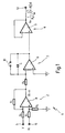
- figure 1 is a block diagram of an embodiment of the device of the analogue type
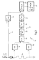
- figure 2 is a block diagram of an embodiment of the logic type of the device.
- N has been calculated by means of formula (1) above, and once the reduction ratio is known (in the case of a motor provided with a reducer), the total angular rotation or linear displacement effected by the motor may easily be calculated.
- a device in its entirety is denoted by, the device being constructed according to this invention for calculating the number of revolutions completed by an electric motor (not shown) in a predetermined period of time, denoted by t1, during which the motor, exhibiting an armature resistance with a value of R, is set in motion by the effect of the connection to a respective source of electrical supply, which provides a supply voltage with a value V, which enables a current of value i to flow through the motor armature.
- Device 1 consists essentially of three circuit units connected in series, namely: an algebraic summation unit 2, an integrating unit 3 and a disconnection unit 4 with a high input impedance and a low output impedance.
- Summation unit 2 is provided with two input terminals 5, 6, to which are fed motor supply voltage V and voltage drop R i, respectively, the latter being established in the armature as current i passes through it.
- These terminals 5, 6 are connected by identical resistances R1 to inverting inputs - and non-inverting inputs +, respectively, of an operational amplifier 8.
- the non-inverting input of the latter is connected to earth by means of a resistance R1, whilst the inverting input is connected to the output by means of a further resistance R1 identical to the aforementioned resistances.
- Integrating unit 3 is of the conventional type, with an input resistance R2, which is connected to the inverting input - of an operational amplifier 9, and to a capacitor C connected between the inverting input and the output of operational amplifier 9.
- the non-inverting input + of amplifier 9 is connected to earth, whilst a switch 10, whose actuation is controlled in synchronism with the electrical supply to the said motor, is connected in parallel with capacitor C, for which purpose the switch is kept open only for the period of time during which the electric motor is supplied with voltage V.
- an entire device constructed according to this invention is denoted by 15 and is designed for calculating the number of revolutions completed by an electric motor M in a predetermined period of time, denoted by t1, during which the motor, exhibiting an armature resistance with a value R, is set in motion by the effect of the connection to a respective source of electrical supply which provides a supply voltage with a value V, which causes a current with a value i to flow in the armature of the motor.
- motor M is arranged in a series circuit supplied, between a terminal 17 and earth, with voltage V, and exhibiting a switch 18 for controlling the electrical supply to the motor, together with a precision resistance Rs with a value much lower than the value of the aforementioned armature resistance R.
- Device 1 5 is provided with two branches, 21 and 22 respectively, converting in an algebraic summation block 23.
- Branch 21 consists of a single integrating block 25, which integrates the value of voltage V for the period of time t1 in which switch 18 is closed.
- Branch 22 comprises a pair of analogue/digital converters 31, 32 connected to the terminals of resistance Rs for recording the respective voltage values V1, V2, and transmitting them to the inputs of an algebraic summation block 33, which provides the difference V2-V1.
- the output of block 33 is connected to a multiplying block 34, which multiplies the value V2-V1 by the inverse of value Rs to obtain the value i of the current flowing in motor M during operation.
- Block 23 effects the difference between the output signals of blocks 25 and 36, whilst the successive block 37 effects the multiplication of the result obtained for the inverse of the product k ⁇ , in order to obtain the value of N similarly to that obtained with reference to device 1.
Landscapes
- Physics & Mathematics (AREA)
- General Physics & Mathematics (AREA)
- Control Of Electric Motors In General (AREA)
- Control Of Direct Current Motors (AREA)
Applications Claiming Priority (2)
| Application Number | Priority Date | Filing Date | Title |
|---|---|---|---|
| IT6811089 | 1989-12-18 | ||
| IT06811089A IT1237696B (it) | 1989-12-18 | 1989-12-18 | Dispositivo di misura del numero di giri dell'albero di un motore elettrico a magneti permanenti. |
Publications (1)
| Publication Number | Publication Date |
|---|---|
| EP0433733A1 true EP0433733A1 (en) | 1991-06-26 |
Family
ID=11307923
Family Applications (1)
| Application Number | Title | Priority Date | Filing Date |
|---|---|---|---|
| EP19900122982 Withdrawn EP0433733A1 (en) | 1989-12-18 | 1990-11-30 | Device for measuring the number of revolutions of the shaft of a permanent magnet electric motor |
Country Status (6)
| Country | Link |
|---|---|
| US (1) | US5172048A (it) |
| EP (1) | EP0433733A1 (it) |
| JP (1) | JPH04210791A (it) |
| BR (1) | BR9006484A (it) |
| IT (1) | IT1237696B (it) |
| RU (1) | RU2027213C1 (it) |
Cited By (2)
| Publication number | Priority date | Publication date | Assignee | Title |
|---|---|---|---|---|
| GB2269568A (en) * | 1992-08-10 | 1994-02-16 | Lansing Linde Ltd | Electrically powered device, eg vehicle with on-demand power steering. |
| FR2791486A1 (fr) * | 1999-03-24 | 2000-09-29 | Valeo Systemes Dessuyage | Moteur electrique a courant continu equipe de moyens perfectionnes de detection de rotation |
Families Citing this family (2)
| Publication number | Priority date | Publication date | Assignee | Title |
|---|---|---|---|---|
| US7196498B2 (en) * | 2004-09-08 | 2007-03-27 | Honeywell International Inc. | Method and apparatus for generator control |
| DE102008040929A1 (de) * | 2008-08-01 | 2010-02-04 | Robert Bosch Gmbh | Verfahren zur Messwertermittlung in einem getaktet angesteuerten System |
Citations (2)
| Publication number | Priority date | Publication date | Assignee | Title |
|---|---|---|---|---|
| US3519906A (en) * | 1968-02-16 | 1970-07-07 | Gen Electric | Dc motor speed signal generating circuit |
| US4691152A (en) * | 1986-02-19 | 1987-09-01 | International Business Machines Corporation | Data disk drive velocity estimator |
Family Cites Families (8)
| Publication number | Priority date | Publication date | Assignee | Title |
|---|---|---|---|---|
| US3705352A (en) * | 1971-02-25 | 1972-12-05 | Westinghouse Electric Corp | Testing system for motor driven apparatus |
| US3708737A (en) * | 1971-05-19 | 1973-01-02 | California Data Corp | Electric motor speed sensing |
| US3836853A (en) * | 1973-10-10 | 1974-09-17 | Gen Motors Corp | Apparatus for measuring the speed of a moving member |
| JPS5716369A (en) * | 1980-07-02 | 1982-01-27 | Fuji Electric Co Ltd | Driving test equipment for rotary machine |
| DE3234683A1 (de) * | 1982-09-18 | 1984-03-22 | Robert Bosch Gmbh, 7000 Stuttgart | Verfahren zur messung der drehzahl eines gleichstrommotors |
| US4535405A (en) * | 1982-09-29 | 1985-08-13 | Microbot, Inc. | Control and force-sensing method and apparatus for motors |
| DE3418573A1 (de) * | 1984-05-18 | 1985-12-05 | Siemens AG, 1000 Berlin und 8000 München | Verfahren und vorrichtung zum stabilisieren der ortskurve eines durch integration gebildeten vektors |
| DE3447090A1 (de) * | 1984-12-22 | 1986-06-26 | Heidelberger Druckmaschinen Ag, 6900 Heidelberg | Verfahren und einrichtung zur bremsenkontrolle eines bewegungsueberwachten und -gesteuerten antriebsmotors in einer druckmaschine |
-
1989
- 1989-12-18 IT IT06811089A patent/IT1237696B/it active IP Right Grant
-
1990
- 1990-11-30 EP EP19900122982 patent/EP0433733A1/en not_active Withdrawn
- 1990-12-14 BR BR909006484A patent/BR9006484A/pt not_active IP Right Cessation
- 1990-12-17 RU SU904894044A patent/RU2027213C1/ru active
- 1990-12-18 JP JP2403262A patent/JPH04210791A/ja not_active Withdrawn
- 1990-12-18 US US07/629,407 patent/US5172048A/en not_active Expired - Fee Related
Patent Citations (2)
| Publication number | Priority date | Publication date | Assignee | Title |
|---|---|---|---|---|
| US3519906A (en) * | 1968-02-16 | 1970-07-07 | Gen Electric | Dc motor speed signal generating circuit |
| US4691152A (en) * | 1986-02-19 | 1987-09-01 | International Business Machines Corporation | Data disk drive velocity estimator |
Non-Patent Citations (1)
| Title |
|---|
| ELECTRONIC ENGINEERING, vol. 46, no. 562, December 1974, pages 48,49, London, GB; M.G. SMART: "Analogue distance indicating device" * |
Cited By (2)
| Publication number | Priority date | Publication date | Assignee | Title |
|---|---|---|---|---|
| GB2269568A (en) * | 1992-08-10 | 1994-02-16 | Lansing Linde Ltd | Electrically powered device, eg vehicle with on-demand power steering. |
| FR2791486A1 (fr) * | 1999-03-24 | 2000-09-29 | Valeo Systemes Dessuyage | Moteur electrique a courant continu equipe de moyens perfectionnes de detection de rotation |
Also Published As
| Publication number | Publication date |
|---|---|
| IT1237696B (it) | 1993-06-15 |
| IT8968110A1 (it) | 1991-06-18 |
| JPH04210791A (ja) | 1992-07-31 |
| IT8968110A0 (it) | 1989-12-18 |
| US5172048A (en) | 1992-12-15 |
| RU2027213C1 (ru) | 1995-01-20 |
| BR9006484A (pt) | 1991-10-01 |
Similar Documents
| Publication | Publication Date | Title |
|---|---|---|
| US4292575A (en) | Control signal transmitter for the commutating device of an electronically commutated d-c motor | |
| EP0114404A1 (en) | Improved magnetic sensing for monitors and controllers | |
| US5744950A (en) | Apparatus for detecting the speed of a rotating element including signal conditioning to provide a fifty percent duty cycle | |
| NL8203285A (nl) | In het lichaam implanteerbare omzetter. | |
| US5172048A (en) | Device for measuring the number of revolutions of the shaft of a permanent magnet electric motor | |
| US4189666A (en) | Speed control system for small size D-C electric motor | |
| RU2005104958A (ru) | Компактное устройство для измерения скорости и направления вращения объекта | |
| US4059799A (en) | Tachometer apparatus | |
| US3137163A (en) | Method of and means for measuring torque of an electric motor drive | |
| US2720620A (en) | Damping circuit for forced balanced galvanometer system | |
| EP0838035B1 (de) | Verfahren und schaltungsanordnung zum ermitteln der drehzahl eines gleichstrommotors | |
| US713257A (en) | Recording electrical measuring instrument. | |
| US3418643A (en) | Memory device in conjunction with a magnetically variable electric signal generator | |
| US3505596A (en) | Hand type tachometer selectively usable as an installed tachometer system | |
| US2891727A (en) | Analogue computer | |
| EP0712001B1 (en) | A method and a circuit system for detecting the speed of rotation of a DC motor | |
| US4652868A (en) | Multi-channel fault monitor using quick-acting interfaces to operate slow-acting indicators | |
| US3323054A (en) | Self-balancing measuring system having anti-hunt magnetic means for slider damping | |
| US4659985A (en) | Electric meter having at least two display registers selected according to a parameter | |
| SU1513376A1 (ru) | Устройство дл измерени температуры обмотки электрической машины | |
| GB2102955A (en) | Improvements relating to servo systems | |
| RU2079808C1 (ru) | Резистивный датчик положения | |
| JPH03223619A (ja) | ポテンショメータ入力回路 | |
| US3348144A (en) | System for measuring speeds of workpieces rotated by motor | |
| SU1534340A1 (ru) | Способ измерени пульсаций электромагнитного момента вентильного электродвигател |
Legal Events
| Date | Code | Title | Description |
|---|---|---|---|
| PUAI | Public reference made under article 153(3) epc to a published international application that has entered the european phase |
Free format text: ORIGINAL CODE: 0009012 |
|
| AK | Designated contracting states |
Kind code of ref document: A1 Designated state(s): DE ES FR GB SE |
|
| RIN1 | Information on inventor provided before grant (corrected) |
Inventor name: SCARTEZZINI, VITO Inventor name: AMPALA, CLAUDIO Inventor name: GIACCARDI, ERALDO |
|
| 17P | Request for examination filed |
Effective date: 19911028 |
|
| 17Q | First examination report despatched |
Effective date: 19921202 |
|
| STAA | Information on the status of an ep patent application or granted ep patent |
Free format text: STATUS: THE APPLICATION IS DEEMED TO BE WITHDRAWN |
|
| 18D | Application deemed to be withdrawn |
Effective date: 19930928 |