EP0433701A2 - Pressure-activated valve - Google Patents
Pressure-activated valve Download PDFInfo
- Publication number
- EP0433701A2 EP0433701A2 EP19900122480 EP90122480A EP0433701A2 EP 0433701 A2 EP0433701 A2 EP 0433701A2 EP 19900122480 EP19900122480 EP 19900122480 EP 90122480 A EP90122480 A EP 90122480A EP 0433701 A2 EP0433701 A2 EP 0433701A2
- Authority
- EP
- European Patent Office
- Prior art keywords
- pressure
- valve body
- flow
- actuated
- valve
- Prior art date
- Legal status (The legal status is an assumption and is not a legal conclusion. Google has not performed a legal analysis and makes no representation as to the accuracy of the status listed.)
- Withdrawn
Links
Images


Classifications
-
- F—MECHANICAL ENGINEERING; LIGHTING; HEATING; WEAPONS; BLASTING
- F16—ENGINEERING ELEMENTS AND UNITS; GENERAL MEASURES FOR PRODUCING AND MAINTAINING EFFECTIVE FUNCTIONING OF MACHINES OR INSTALLATIONS; THERMAL INSULATION IN GENERAL
- F16F—SPRINGS; SHOCK-ABSORBERS; MEANS FOR DAMPING VIBRATION
- F16F9/00—Springs, vibration-dampers, shock-absorbers, or similarly-constructed movement-dampers using a fluid or the equivalent as damping medium
- F16F9/32—Details
- F16F9/44—Means on or in the damper for manual or non-automatic adjustment; such means combined with temperature correction
- F16F9/46—Means on or in the damper for manual or non-automatic adjustment; such means combined with temperature correction allowing control from a distance, i.e. location of means for control input being remote from site of valves, e.g. on damper external wall
-
- F—MECHANICAL ENGINEERING; LIGHTING; HEATING; WEAPONS; BLASTING
- F16—ENGINEERING ELEMENTS AND UNITS; GENERAL MEASURES FOR PRODUCING AND MAINTAINING EFFECTIVE FUNCTIONING OF MACHINES OR INSTALLATIONS; THERMAL INSULATION IN GENERAL
- F16F—SPRINGS; SHOCK-ABSORBERS; MEANS FOR DAMPING VIBRATION
- F16F9/00—Springs, vibration-dampers, shock-absorbers, or similarly-constructed movement-dampers using a fluid or the equivalent as damping medium
- F16F9/32—Details
- F16F9/34—Special valve constructions; Shape or construction of throttling passages
-
- B—PERFORMING OPERATIONS; TRANSPORTING
- B60—VEHICLES IN GENERAL
- B60G—VEHICLE SUSPENSION ARRANGEMENTS
- B60G2600/00—Indexing codes relating to particular elements, systems or processes used on suspension systems or suspension control systems
- B60G2600/22—Magnetic elements
- B60G2600/26—Electromagnets; Solenoids
Definitions
- the invention relates to a pressure-operated valve according to the preamble of the main claim.
- the pressure-actuated valve comprises a valve body which is actuated by a spring element in the closing direction against a valve seat. If the valve body sits on its valve seat, a flow opening is closed and a chamber containing an upstream pressure is separated from a chamber containing an downstream pressure.
- the valve body can close the flow opening, ie the valve body covers the flow opening.
- the inflow-side pressure acts on the valve body in the area of the flow opening.
- the part of the valve body covering the flow opening represents an effective pressure area for the inflow-side pressure. If the inflow-side pressure reaches a certain value, this pressure can lift the valve body against the closing force of the spring element from the valve seat and pressure medium can flow from the first chamber into the flow into the second chamber. Should also be a large flow of pressure medium from the first chamber into the second chamber can flow without the pressure medium flow in the area of the flow opening being throttled too much, the flow opening must be correspondingly large.
- the spring element must be dimensioned accordingly so that the spring element acting on the valve body can close the flow opening.
- the pressure medium can only flow from one specific chamber into the other chamber.
- the pressure-actuated valve has the function of a so-called pressure-maintaining valve or pressure-limiting valve or safety valve, based on this only possible flow direction. A flow through the known pressure-operated valve in the opposite direction is not possible.
- the pressure-actuated valve with the characterizing features of the main claim has the advantage that a relatively weak and therefore small-sized spring element can be used to secure a large pressure with a large possible flow opening.
- An intermediate pressure which forms in an intermediate chamber when the pressure-actuated valve opens provides the advantage that, as the pressure medium flow increases, the pressure on the inflow side remains more or less constant, as desired. It is even possible that the pressure on the inflow side decreases as the pressure medium flow increases. It is a question of dimensioning.
- the pressure-operated valve has the advantage that it can be built so that it can be flowed through in both directions of flow.
- the valve can advantageously be constructed in such a way that the pressure difference in the area of the valve is the same for both flow directions or, depending on the dimensioning, the respective pressure difference can be chosen differently for both flow directions.
- valve Since only one spring element is required to secure the respective upstream pressure for both flow directions, the valve is very simple and has a small size.
- the pressure-actuated valve advantageously has a relatively small and light construction, it is particularly suitable for protecting a pressure medium flow which is exchanged between work spaces of a damping system, in particular a shock absorber.
- the pressure-actuated valve can advantageously influence the damping force in the shock absorber. It can be present as the sole valve in the shock absorber or it can e.g. B. as an additional safety valve in parallel with another valve, e.g. B. an electromagnetically actuated valve.
- the pressure operated valve can be used in such a way that as soon as there is too much pressure in one of the work rooms, it opens a path to the other work room. Depending on the design of the pressure-actuated valve, both flow directions can be secured with a single pressure-actuated valve.
- FIGS. 1 to 4 each show an exemplary embodiment and FIGS. 5 to 7 show special details.
- the pressure-actuated valve according to the invention can be used in any system in which a pressure of a pressure medium is to be secured or a pressure difference between an upstream and an downstream pressure of the pressure medium is to be secured, set or controlled.
- a shock absorber was chosen as an application example for the pressure-actuated valve according to the invention.
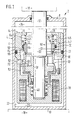
- FIG. 1 shows the first embodiment.
- a shock absorber 2 has a cylinder 4 with a casing tube 6, shown in sections, with a first end face 8 and with a second end face 10.
- a piston rod 12 protrudes from the first end face 8 of the casing tube 6. Only the two ends of the piston rod 12 are shown.
- the piston rod 12 is connected at one end to a stepped damper piston 14 and at the other end it is articulated on a first mass 16 indicated by dash-dotted lines. That is, the damper piston 14 is connected to the first mass 16.
- the damper piston 14 comprises a housing 15.
- the second End face 10 is connected to a second mass 18 indicated by dash-dotted lines.
- the first mass 16 is for example a vehicle body and the second mass 18 is e.g. B. a vehicle axle.
- the damper piston can slide axially with the interposition of a guide ring 20 on an inner lateral surface 22 of the tubular casing 6.
- the guide ring 20 also has the function of a seal.
- An interior of the cylinder 4 is divided into a first working space 24 and a second working space 26 by the damper piston 14. In the drawing, the first working space 24 is above and the second working space 26 is below the damper piston 14.
- the working spaces 24, 26 are at least partially filled with a pressure medium.
- the two working spaces 24, 26 are connected to one another via a flow connection 28.
- a throttle point 30 is provided in the course of the flow connection 28.
- the throttle point 30 can be changed by actuating a control slide 32.
- the control slide 32 is provided on the end face with a slide control edge 36.
- the control slide 32 can be actuated in the axial direction against a force of a spring 40.
- the slide control edge 36 of the control slide 32 increasingly lifts off the fixed control edge 34; d. H. with increasing current supply to the magnetic coil 38, a cross-sectional area at the throttle point 30 is increased.
- the solenoid 38 is not energized, the throttle point 30 is closed or the cross-sectional area reaches its minimum.
- the flow connection 28 comprises a spring chamber 42, a chamber 44, longitudinal openings 46, a groove 48, the throttle point 30, a slide chamber 50 and transverse openings 52. Is the pressure in the first Working space 24 larger than in the second working space 26, depending on the position of the control slide 32, the pressure medium can flow through the flow connection 28 in the order of enumeration. If the pressure in the second working space 26 is greater than in the first working space 24, then the pressure medium flows through the flow connection 28 in the opposite direction.
- the cross-sectional area of the throttle point 30 determines a damping force of the shock absorber 2. If the control slide 32 has a setting position in which the cross-sectional area of the throttle point 30 is very small and at the same time one of the masses 16, 18 is moved very quickly relative to the other mass 16, 18, this creates 2 large damping forces within the shock absorber, which means that, depending on the relative movement, a very high pressure is generated in one of the two working spaces 24, 26. If no further measures are provided, the pressure in one of the working spaces 24, 26 can possibly reach a level which could lead to failure of the shock absorber 2 or undesirably large damping forces occur. To prevent this, the pressure-actuated valve 60 according to the invention is installed in the flow connection 28 of the shock absorber 2.
- the pressure-actuated valve 60 comprises a valve body 62, a spring element 64, a sealing element 70 and at least one region of the housing 15 surrounding the valve body 62, the spring element 64 and the seal 70.
- the spring element 64 can consist of a spring or of several cooperating springs.
- Provided on the housing 15 of the damper piston 14 is a guide bore 66 which is approximately concentric with the piston rod 12.
- the valve body 62 has, roughly speaking, a sleeve-like shape with an outer guide jacket 68.
- the valve body 62 is mounted with its guide jacket 68 in the guide bore 66 of the housing 15 so as to be displaceable in the axial direction. So that by a between the guide jacket 68 of the valve body 62 and the guide bore 66 of the housing 15, no pressure medium can flow, a groove is inserted in the area of the guide bore 66 and the sealing element 70 is inserted therein.
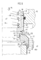
- valve body 62 is shown in FIG. 1 transversely to the circumference, but cut along its axis, as a result of which two mirror-image cut surfaces can be seen in FIG. For the purpose of clarification, one of these cut surfaces is shown again in FIG. 5 on a different scale. In all figures, the same or equivalent parts are provided with the same reference numerals.
- the sleeve-like valve body 62 has an end face 72 which extends into the spring chamber 42.
- the spring element 64 is installed in the spring chamber 42.
- the spring element 64 acts with one spring end against the housing 15 of the damper piston 14 and with its other spring end against the end face 72 of the valve body 62.
- the spring element 64 tries to actuate the valve body 62 with a closing force in a closing direction until the valve body 62 comes to rest on a shoulder 74 of the housing 15 which runs transversely to the closing direction.
- the closing direction is symbolically indicated in the drawing by an arrow 75.
- the part of the valve body 62 which comes into contact with the shoulder 74 of the housing 15 is referred to below as the valve body sealing region 76.
- the part of the housing 15 on which the valve body sealing region 76 comes to rest is referred to below as the counter-sealing region 78.
- the valve body sealing area 76 and the counter-sealing area 78 together form a sealing point 80
- the guide jacket 68 of the valve body 62 has a diameter denoted by D1.
- the sealing point 80 between the shoulder 74 of the housing 15 and the valve body 62 runs in a circular shape and has a diameter denoted by D2.
- the valve body 62 has one to the guide jacket 68 is approximately concentric inner bore jacket 82 with a diameter D3.
- a shoulder 84 is formed between the guide jacket 68 and the sealing point 80.
- the shoulder 84 on the valve body 62 extends transversely to the closing or opening direction in FIG. 5; however, as shown in FIG. 1, it can also run obliquely.
- an effective pressure area 85 is obtained from the area difference of the area with the diameter D1 minus the area with the diameter D2.
- the effective pressure area 85 of the valve body 62 protrudes into a chamber 86.
- the chamber 86 is connected to the slide chamber 50 via longitudinal bores 88.
- the same pressure p2 prevails in the chamber 86 as in the slide chamber 50 and, because of the transverse openings 52, also the same pressure p2 as in the second working chamber 26.
- the chamber 86 and the longitudinal bores 88 are also part of the flow connection 28.
- the pressure p2 prevailing in the chamber 86 acts on the effective pressure surface 85 of the valve body 62.
- a cylindrical part 90 can be provided on the valve body 62 between the shoulder 84 and the sealing point 80. The pressure prevailing in the chamber 86 can thus act unhindered up to the sealing point 80 and the valve body sealing region 76 of the valve body 62 is located on the end of the cylindrical part 90 of the valve body 62 which is preferably edge-shaped and faces the counter-sealing region 78.
- the pressure p1 prevails in the spring chamber 42, the chamber 44 and the longitudinal openings 46 as in the first working chamber 24.
- the pressure p1 is greater than the pressure p2 or pressure p1 is equal to pressure p2 or pressure p1 is less than pressure p2.
- the pressure p1 acts on the end face 72 of the valve body 62 in the closing direction symbolized by the arrow 75.
- the diameter D3 of the bore casing 82 is smaller than the diameter D2 of the sealing point 80.
- An annular part extending between the two diameters D2, D3 on the side of the valve body 62 facing away from the end face 72 is referred to below as the end face 92.
- a cylindrical shoulder 94 with a diameter D4 runs on the housing 15.
- the diameter D4 is smaller than the diameter D2.
- the end face 92 of the valve body 62 is graduated, u. a. because of a cylindrical shoulder 95 with a diameter D5.
- the diameter D5 is larger than the diameter D3, but smaller than the diameter D2 of the sealing point 80.
- the diameter D4 is slightly larger than the diameter D5.
- the cylindrical shoulder 95 of the valve body 62 overlaps the cylindrical shoulder 94 of the housing 15 in the axial direction, so that a narrow, annular throttle point 98 is formed between these two cylindrical shoulders 94, 95.
- the sealing point 80 is closed due to the closing force of the spring element 64.
- the force in the opening direction (counter to arrow 75) becomes increasingly larger, or with decreasing pressure p1 in chamber 44, the sum of the closing forces becomes increasingly smaller.
- the valve body sealing region 76 lifts off from the counter-sealing region 78 and a flow opening 100 opens between the valve body sealing region 76 of the valve body 62 and the counter-sealing region 78 of the housing 15. Pressure medium can now escape from the chamber 86 flow through the flow opening 100 in the direction of the chamber 44.
- the pressure p2 can also be referred to as the upstream pressure.
- the respective other pressure, here the pressure p1 in the chamber 44 can be referred to as the downstream pressure.
- the pressure medium is throttled again in the area of the throttle point 98, so that an intermediate pressure p3 forms in the area between the diameter D2 and the diameter D5, ie in the intermediate chamber 99, which, depending on Size of the flow opening 100 and the throttle point 98, is in the range between the pressure p2 and the pressure p1.
- the intermediate pressure p3 can be almost the same as the pressure on the inflow side. Since the intermediate pressure p3 is greater than the pressure p1, as soon as a certain flow area 100 is opened in the area of the sealing point 80, the valve body 62 is increasingly torn in the opening direction (counter to arrow 75), as a result of which a very large flow opening 100 can advantageously be formed immediately.
- the pressure-actuated valve 60 can be designed such that the pressure difference between the pressure p2 and the p1 remains largely constant regardless of a size of the pressure medium stream flowing through.
- the pressure p2 in the chamber 86 is greater than the pressure p1 in the chamber 44 and the pressure difference reaches a certain value, the flow opening 100 of the pressure-actuated valve 60 opens.
- the pressure-actuated valve 60 remains closed, regardless of the pressure difference.
- FIG. 2 shows an exemplary embodiment for this.
- Figure 2 shows the second embodiment.
- the diameter D2 of the sealing point 80 is larger than the diameter D1 of the guide jacket 68 of the valve body 62.
- the pressure-actuated valve 60 shown here therefore opens its flow opening 100 when the pressure p1 in the chamber 44 is sufficiently greater than the pressure p2 in the chamber 86, and the pressure medium can flow out of the chamber 44 in the direction of the chamber 86.
- the pressure p1 in the chamber 44 can be referred to as the upstream pressure.
- the intermediate chamber 99 and then the throttle point 98 adjoins the sealing point 80 in the direction of flow before the pressure medium reaches the chamber 86.
- the pressure-actuated valve 60 of the second exemplary embodiment can also keep the pressure p1 in the chamber 44 constant, irrespective of the size of the pressure medium stream flowing through, in a manner corresponding to that described for the first exemplary embodiment according to FIG. 1. It is possible for a person skilled in the art to transfer further details mentioned for the first exemplary embodiment with reference to FIGS. 1 and 5 to the second exemplary embodiment according to FIG. 2.
- one of the pressure-actuated valves 60 explained on the basis of the first two exemplary embodiments is installed in the shock absorber 2, then either the pressure p1 in the chamber 44, ie in the first working chamber 24, or the pressure p2 in the chamber 86, ie in the second working chamber 26, can be at one maximum value can be limited. If the pressures p1, p2 in both work spaces 24, 26 are to be limited with the pressure-actuated valve 60, two of the valves 60 shown in FIGS. 1 and 2 are to be installed in the flow connection 28 of the shock absorber 2. Since the pressure-actuated valves 60 are relatively small and since the required spring element 64 can be relatively weak and therefore small, it is often possible to install two pressure-actuated valves 60 in the shock absorber 2 without any problems.
- the variants of the pressure-actuated valve 60 offer the advantage that both the pressure p1 in the first working space 24 and the pressure p2 in the second working space 26 can be limited with a single pressure-actuated valve 60.
- the pressure-actuated valve 60 can be flowed through in two flow directions.
- Figure 3 shows the third embodiment.
- the valve body 62 comprises a first valve body part 111 and a second valve body part 112.
- a part of the pressure-actuated valve 60 shown in FIG. 3 is identified by a dash-dotted line and marked VI. This part of the pressure-actuated valve 60 is shown again in FIG. 6 for the purpose of illustration with a changed scale.
- first sealing point 115 and a first throttle point 116 between the first valve body part 111 and the second valve body part 112.
- a first intermediate chamber 117 is formed between them.
- second sealing point 119 and a second throttling point 120 between the second valve body part 112 and the housing 15.
- a second intermediate chamber 118 is also formed in between.
- the throttling points 116 and 120 are designed according to FIG. When the pressure-actuated valve 60 is closed, the sealing points 115, 119 separate the chamber 44 from the chamber 86.
- the second sealing point 119 has a diameter D7.
- the diameter of the first sealing point 115 is also denoted here by D2 and the diameter of the guide jacket 68 of the first valve body part 111 is denoted by D1.
- the diameter D7 of the second sealing point 119 is larger than the diameter D2 of the first sealing point 115. If the pressure p2 in the chamber 86 is greater than the pressure p1 in the chamber 44, then because D7 is larger than D2, the second valve body part 112 in Closing direction (arrow 75) pressed against shoulder 74 of housing 15; d. H. if p2 is greater than p1, then the second sealing point 119 is closed.
- first sealing point 115 When the first sealing point 115 is closed, a first valve body sealing region 121 of the first valve body part 111 in the form of a peripheral edge comes into contact with a first counter sealing region 122 of the second valve body part 112 facing the first valve body sealing region 121.
- Sealing point 119 is in the form of a circumferential edge with the diameter D7 and a second valve body sealing region 126 of the second valve body part 112 abuts a second counter-sealing region 127 which forms on the shoulder 74 of the housing 15.
- the diameter D2 of the first sealing point 115 is smaller than the diameter D1 of the guide jacket 68 of the first valve body part 111 of the valve body 62.
- the area difference of the surface with the diameter D1, minus the surface with the diameter D2, results in a on the first valve body part 111 the first effective pressure surface 131 facing the chamber 86.
- the pressure p2 prevailing in the chamber 86 can act on the first valve body part 111 in the opening direction (counter to arrow 75) via the pressure surface 131.
- pressure p2 in chamber 86 may be referred to as the upstream pressure.
- the pressure-actuated valve 60 operates as if the two valve body parts 111 and 112 were firmly joined together, and from a certain pressure difference between the pressure p1 and the pressure p2, only the second sealing point 119 between the second valve body part 112 and the housing can 15 open.
- the diameter D7 of the second sealing point 119 is larger than that Diameter D1 of the guide jacket 68 of the valve body 62.
- the resulting difference in the areas forms a second effective pressure surface 135 facing the chamber 44. Because of the second effective pressure surface 135 on the second valve body part 112, the second sealing point 119 between the second valve body part can start from a certain differential pressure 112 and the housing 15 open, whereby a second flow opening 136 is opened between the second valve body part 112 and the housing 15.
- Figure 4 shows the fourth embodiment.
- the diameter D2 of the first sealing point 115 between the first valve body part 111 and the second valve body part 112 is larger than the diameter D1 of the guide jacket 68
- the diameter D7 of the second sealing point 119 between the second valve body part 112 and the shoulder 74 of the housing 15 is smaller than the diameter D1 of the guide jacket 68 of the valve body 62.
- the first effective pressure surface 131 of the first valve body part 111 faces the chamber 44
- the second effective pressure surface 135 of the second valve body part 112 is the chamber 86 facing.
- the first flow opening 132 is opened and, with a corresponding pressure difference, when the pressure p2 in the chamber 86 is greater than the pressure p1 in the chamber 44, the second flow opening 136 between the second valve body part 112 and the housing 15 is opened.
- the first throttle point 116 is arranged behind the first sealing point 115.
- the second flow opening 136 comes in the region of the second flow opening 136 first the second sealing point 119 and then the second throttle point 120.
- first sealing point 115 and the first throttle point 116 there is the first intermediate chamber 117 and between the The second intermediate chamber 118 is located at the second sealing point 119 and the second throttling point 120. Further details explained with reference to FIG. 6 can also be applied analogously to the fourth exemplary embodiment.
- FIGS. 3 and 4 offer the additional advantage that the flow of the pressure medium can be influenced in the two possible flow directions. Since the pressure medium flows from the first working chamber 24 into the second working chamber 26 and sometimes in the opposite direction in many embodiments of the shock absorber 2, the third and fourth exemplary embodiments are particularly well suited for a large number of shock absorber embodiments.
- valve body 62 when the valve body 62 is actuated in the closing direction (arrow 75), the flow openings 100, 132, 136 of the respective sealing points 80, 115, 119 are essentially completely closed because the valve body sealing region 76, 121, which is formed in the form of an edge, 126 comes into contact with the respective counter sealing area 78, 122, 127.
- the pressure-actuated valve 60 explained with reference to FIGS. 1 to 6 belongs to the group of the so-called seat valves. However, it is also possible to design the valve body 62 or the valve body parts 111, 112 of the valve body 62 in a slide-like manner, which is to be explained with reference to FIG. 7.
- FIG. 7 shows a further possibility for designing the valve body 62 of the pressure-actuated valve 60 in the region of the flow opening 100 between the valve body 62 and the housing 15.
- the valve body 62 is designed in the manner of a slide.
- a shoulder 141 of the valve body 62 comes to a shoulder 142 of the housing 15 in the closed position Investment.
- the slide-shaped valve body 62 covers an edge on the housing 15 in the area of the sealing point 80 in the axial direction.
- An annular gap is present in the area of the sealing point 80.
- the annular gap in the area of the sealing point 80 is relatively small, so that an average diameter of this annular gap can be referred to as the diameter D2 of the first sealing point 80.
- the pressure-actuated valve 60 shown in detail in FIG. 7 can also be modified in such a way that the diameter D2 of the annular gap of the sealing point 80 is larger than the diameter D1 of the guide jacket 68, so that the ratios obtained are approximately the same as those in the figure 2 shown second embodiment.
- a further flow connection 146 with z. B. a further pressure-actuated valve 147, an aperture, an electromagnetically actuated valve or the like between the two working spaces 24, 26 may be present.
- the pressure-actuated valve 60 according to the invention can also be arranged in a flow connection which is not provided in the damper piston 14 but at another location inside or outside the shock absorber 2.
- the pressure-actuated valve 60 is arranged in the flow connection 28 parallel to the throttle point 30 which can be controlled via the control slide 32.
- the pressure-actuated valve 60 will be dimensioned such that, in the normal case, the damping force of the shock absorber 2 is controlled solely via the throttle point 30, and only when an unusually large external force that displaces the two masses 16, 18 against one another does the pressure p1 or p2 is sufficient to open the pressure-actuated valve 60.
- the pressure p1 or p2 in the working spaces 24, 26 can thus be limited to an uncritical value.
- the unusually large, the two masses 16, 18 mutually displacing force can, for. B. occur when the shock absorber 2 is installed in a vehicle between the vehicle body and the vehicle axle and when this vehicle runs at high speed over a high obstacle.
- the pressure-actuated valve 60 can also be present as the only valve in the flow connection 28 of the shock absorber 2. That means there can be further throttling points, e.g. B. the throttle point 30 and thus also the control slide 32 are omitted, and the pressure-actuated valve 60 is the only one that controls the damping force of the shock absorber 2 of the damping system.
- the pressure medium flows essentially radially from the outside inwards or from the inside outwards through the respective flow opening 100, 132, 136 in the region of the sealing point 80, 115, 119.
- the pressure medium flows into the the chamber 44 or 86 containing the downstream pressure flows in, it is deflected more or less, depending on how far the valve body 62 is actuated in the opening direction, in the axial direction, specifically against the opening direction.
- the pressure medium is deflected in the axial direction by the shoulder 95 of the valve body 62 or the valve body parts 111, 112.
- a particular advantage is that in all of the exemplary embodiments (FIGS. 1 to 7), given the inflow-side pressure, the size of the respective effective pressure area 85, 131, 135 is the only influence on the opening force.
- the effective pressure area 85, 131, 135 is completely independent of the flow opening 100, 132, 136 that can be opened.
- the spring element 64 only the size of the respectively effective pressure area 85, 131, 135 has to be taken into account to a large extent. So you can z. B.
- the sealing element 70 may be dispensed with.
- the embodiments of the pressure-actuated valve 60 according to FIGS. 3, 4 and 6 have the further advantage that the pressure medium flow can be influenced in both directions with a single pressure-actuated valve 60. Only one spring element 64 is advantageously required for this. Nevertheless, e.g. B. when the pressure medium flows from the first working space 24 into the second working space 26, the inflow-side pressure, ie the pressure p1 in the chamber 44 or in the first working space 24, can be brought to a high value and when the pressure medium flows from the second working space 26 in the first working space 24, the inflow-side pressure, ie the pressure p2 in the chamber 86 or in the second working space 26, can be kept very small.
- the inflow-side pressure ie the pressure p1 in the chamber 44 or in the first working space
- the same can be achieved if the effective pressure area 131 is selected to be relatively small and the effective pressure area 135 is relatively large for the pressure ratio mentioned as an example.
- the two respective inflow-side pressures p1 and p2 can thus be controlled independently of one another for both flow directions.
- the pressure-actuated valve 60 is particularly well suited for shock absorbers, in particular for so-called single-tube shock absorbers and also for so-called two-tube shock absorbers.
Landscapes
- Engineering & Computer Science (AREA)
- General Engineering & Computer Science (AREA)
- Mechanical Engineering (AREA)
- Safety Valves (AREA)
- Fluid-Damping Devices (AREA)
Abstract
Description
Die Erfindung betrifft ein druckbetätigtes Ventil nach der Gattung des Hauptanspruchs. Das druckbetätigte Ventil umfaßt einen Ventilkörper, der von einem Federelement in Schließrichtung gegen einen Ventilsitz betätigt wird. Sitzt der Ventilkörper auf seinem Ventilsitz, so ist eine Durchflußöffnung geschlossen und es wird eine einen zuströmseitigen Druck enthaltende Kammer von einer einen abströmseitigen Druck enthaltendenen Kammer getrennt.The invention relates to a pressure-operated valve according to the preamble of the main claim. The pressure-actuated valve comprises a valve body which is actuated by a spring element in the closing direction against a valve seat. If the valve body sits on its valve seat, a flow opening is closed and a chamber containing an upstream pressure is separated from a chamber containing an downstream pressure.
Der Ventilkörper kann, je nach Druckdifferenz zwischen dem zuströmseitigen Druck und dem abströmseitigen Druck, die Durchflußöffnung verschließen, d. h. der Ventilkörper deckt die Durchflußöffnung ab. Der zuströmseitige Druck wirkt im Bereich der Durchflußöffnung auf den Ventilkörper. Der die Durchflußöffnung abdeckende Teil des Ventilkörpers stellt eine wirksame Druckfläche für den zuströmseitigen Druck dar. Erreicht der zuströmseitige Druck einen bestimmten Wert, so kann dieser Druck den Ventilkörper entgegen der Schließkraft des Federelementes von dem Ventilsitz abheben und es kann Druckmedium aus der ersten Kammer in die zweite Kammer strömen. Soll auch ein großer Druckmediumstrom aus der ersten Kammer in die zweite Kammer strömen können, ohne daß der Druckmediumstrom im Bereich der Durchflußöffnung zu stark angedrosselt wird, so muß die Durchflußöffnung entsprechend groß sein. Ist die Durchflußöffnung groß, so muß, damit das auf den Ventilkörper wirkende Federelement die Durchflußöffnung verschließen kann, das Federelement entsprechend dimensioniert sein. Je größer die Durchflußöffnung ist, umso stärker muß das Federelement sein, um den zuströmseitigen Druck auf einem gewünschten Wert halten zu können.Depending on the pressure difference between the upstream pressure and the downstream pressure, the valve body can close the flow opening, ie the valve body covers the flow opening. The inflow-side pressure acts on the valve body in the area of the flow opening. The part of the valve body covering the flow opening represents an effective pressure area for the inflow-side pressure. If the inflow-side pressure reaches a certain value, this pressure can lift the valve body against the closing force of the spring element from the valve seat and pressure medium can flow from the first chamber into the flow into the second chamber. Should also be a large flow of pressure medium from the first chamber into the second chamber can flow without the pressure medium flow in the area of the flow opening being throttled too much, the flow opening must be correspondingly large. If the flow opening is large, the spring element must be dimensioned accordingly so that the spring element acting on the valve body can close the flow opening. The larger the flow opening, the stronger the spring element must be in order to be able to keep the inflow-side pressure at a desired value.
Sollen bei dem bekannten druckbetätigten Ventil hohe Drücke abgesichert werden können, ohne daß bei großen Durchflußströmen eine zu starke Androsselung des Druckmediumstromes erfolgt, so ist ein starkes Federelement erforderlich, was ein sehr groß und massereich bauendes druckbetätigtes Ventil zur Folge hat.If, in the known pressure-actuated valve, high pressures can be secured without the pressure medium flow being excessively throttled in the case of large flow rates, a strong spring element is required, which results in a very large and massively constructed pressure-actuated valve.
Bei dem bekannten druckbetätigten Ventil kann das Druckmedium nur aus einer bestimmten Kammer in die andere Kammer strömen. Das druckbetätigte Ventil hat, bezogen auf diese allein mögliche Durchflußrichtung, die Funktion eines sogenannten Druckhalteventils bzw. Druckbegrenzungsventils bzw. Sicherheitsventils. Eine Durchströmung des bekannten druckbetätigten Ventils in entgegengesetzter Richtung ist nicht möglich.In the known pressure-operated valve, the pressure medium can only flow from one specific chamber into the other chamber. The pressure-actuated valve has the function of a so-called pressure-maintaining valve or pressure-limiting valve or safety valve, based on this only possible flow direction. A flow through the known pressure-operated valve in the opposite direction is not possible.
Das druckbetätigte Ventil mit den kennzeichnenden Merkmalen des Hauptanspruchs weist demgegenüber den Vorteil auf, daß mit einem relativ schwachen und deshalb kleinbauenden Federelement ein großer Druck bei gleichzeitig großer möglicher Durchflußöffnung abgesichert werden kann.The pressure-actuated valve with the characterizing features of the main claim has the advantage that a relatively weak and therefore small-sized spring element can be used to secure a large pressure with a large possible flow opening.
Durch die in den Unteransprüchen aufgeführten Maßnahmen sind vorteilhafte Weiterbildungen und Verbesserungen des druckbetätigten Ventils möglich.Advantageous further developments and improvements of the pressure-actuated valve are possible through the measures listed in the subclaims.
Durch einen bei sich öffnendem druckbetätigten Ventil in einer Zwischenkammer sich ausbildenden Zwischendruck erhält man den Vorteil, daß bei zunehmendem Druckmediumstrom der zuströmseitige Druck, je nach Wunsch, mehr oder weniger konstant bleibt. Es ist sogar möglich, daß bei zunehmendem Druckmediumstrom der zuströmseitige Druck abnimmt. Es ist eine Frage der Dimensionierung.An intermediate pressure which forms in an intermediate chamber when the pressure-actuated valve opens provides the advantage that, as the pressure medium flow increases, the pressure on the inflow side remains more or less constant, as desired. It is even possible that the pressure on the inflow side decreases as the pressure medium flow increases. It is a question of dimensioning.
Das druckbetätigte Ventil hat den Vorteil, daß es so gebaut werden kann, daß es in beide Strömungsrichtungen durchströmbar ist. Das Ventil kann in vorteilhafter Weise so gebaut werden, daß die Druckdifferenz im Bereich des Ventils für beide Strömungsrichtungen gleich groß ist oder, je nach Dimensionierung, kann auch die jeweilige Druckdifferenz für beide Strömungsrichtungen verschieden gewählt werden.The pressure-operated valve has the advantage that it can be built so that it can be flowed through in both directions of flow. The valve can advantageously be constructed in such a way that the pressure difference in the area of the valve is the same for both flow directions or, depending on the dimensioning, the respective pressure difference can be chosen differently for both flow directions.
Da zur Absicherung des jeweils zuströmseitigen Druckes für beide Strömungsrichtungen nur ein Federelement erforderlich ist, ist das Ventil sehr einfach und baut klein.Since only one spring element is required to secure the respective upstream pressure for both flow directions, the valve is very simple and has a small size.
Da das druckbetätigte Ventil in vorteilhafter Weise relativ klein und leicht baut, ist es in besonderem Maße zur Absicherung eines zwischen Arbeitsräumen eines Dämpfungssystems, insbesondere eines Stoßdämpfers, sich austauschenden Druckmediumstromes geeignet. Das druckbetätigte Ventil kann bei dem Stoßdämpfer in vorteilhafter Weise die Dämpfungskraft beeinflussen. Es kann dabei als alleiniges Ventil in dem Stoßdämpfer vorhanden sein oder es kann z. B. als zusätzliches Sicherheitsventil parallel neben einem anderen Ventil, z. B. einem elektromagnetisch betätigbaren Ventil vorhanden sein. Das druckbetätigte Ventil kann hierbei so angewendet werden, daß es, sobald in einem der Arbeitsräume ein zu großer Druck herrscht, es einen Weg in den jeweils anderen Arbeitsraum öffnet. Je nach Ausgestaltung des druckbetätigten Ventils können mit einem einzigen druckbetätigten Ventil beide Strömungsrichtungen abgesichert werden.Since the pressure-actuated valve advantageously has a relatively small and light construction, it is particularly suitable for protecting a pressure medium flow which is exchanged between work spaces of a damping system, in particular a shock absorber. The pressure-actuated valve can advantageously influence the damping force in the shock absorber. It can be present as the sole valve in the shock absorber or it can e.g. B. as an additional safety valve in parallel with another valve, e.g. B. an electromagnetically actuated valve. The pressure operated valve can be used in such a way that as soon as there is too much pressure in one of the work rooms, it opens a path to the other work room. Depending on the design of the pressure-actuated valve, both flow directions can be secured with a single pressure-actuated valve.
Vier Ausführungsbeispiele der Erfindung sind in der Zeichnung vereinfacht dargestellt und in der nachfolgenden Beschreibung näher erläutert. Es zeigen die Figuren 1 bis 4 je ein Ausführungsbeispiel und die Figuren 5 bis 7 spezielle Einzelheiten.Four exemplary embodiments of the invention are shown in simplified form in the drawing and are explained in more detail in the description below. FIGS. 1 to 4 each show an exemplary embodiment and FIGS. 5 to 7 show special details.
Das erfindungsgemäße, druckbetätigte Ventil kann in jedweder Anlage, in der ein Druck eines Druckmediums abgesichert bzw. eine Druckdifferenz zwischen einem zuströmseitigen und einem abströmseitigen Druck des Druckmediums abgesichert, eingestellt oder gesteuert werden soll, eingesetzt werden. Obwohl nicht allein darauf beschränkt, wurde in den Ausführungsbeispielen der vorliegenden Patentanmeldung für das erfindungsgemäße, druckbetätigte Ventil ein Stoßdämpfer als Anwendungsbeispiel gewählt.The pressure-actuated valve according to the invention can be used in any system in which a pressure of a pressure medium is to be secured or a pressure difference between an upstream and an downstream pressure of the pressure medium is to be secured, set or controlled. Although not only limited to this, in the exemplary embodiments of the present patent application a shock absorber was chosen as an application example for the pressure-actuated valve according to the invention.
Die Figur 1 zeigt das erste Ausführungsbeispiel. Ein Stoßdämpfer 2 hat einen Zylinder 4 mit einem abschnittsweise dargestellten Mantelrohr 6 mit einer ersten Stirnseite 8 und mit einer zweiten Stirnseite 10. Aus der ersten Stirnseite 8 des Mantelrohres 6 ragt eine Kolbenstange 12 heraus. Von der Kolbenstange 12 sind nur deren beiden Enden dargestellt. Die Kolbenstange 12 ist mit einem Ende mit einem abgestuften Dämpferkolben 14 verbunden und mit einem anderen Ende ist sie an einer strichpunktiert angedeuteten ersten Masse 16 angelenkt. Das heißt, der Dämpferkolben 14 ist mit der ersten Masse 16 verbunden. Der Dämpferkolben 14 umfaßt ein Gehäuse 15. Die zweite Stirnseite 10 ist mit einer strichpunktiert angedeuteten zweiten Masse 18 verbunden. Die erste Masse 16 ist beispielsweise ein Fahrzeugaufbau und die zweite Masse 18 ist z. B. eine Fahrzeugachse. Der Dämpferkolben kann unter Zwischenlage eines Führungsringes 20 an einer inneren Mantelfläche 22 des Mantelrohres 6 axial gleiten. Der Führungsring 20 hat gleichzeitig die Aufgabe einer Dichtung. Ein Innenraum des Zylinders 4 wird durch den Dämpferkolben 14 in einen ersten Arbeitsraum 24 und in einen zweiten Arbeitsraum 26 unterteilt. In der Zeichnung befindet sich der erste Arbeitsraum 24 oberhalb und der zweite Arbeitsraum 26 unterhalb des Dämpferkolbens 14. Die Arbeitsräume 24, 26 sind zumindest teilweise mit einem Druckmedium gefüllt.Figure 1 shows the first embodiment. A
Die beiden Arbeitsräume 24, 26 sind über eine Strömungsverbindung 28 miteinander verbunden. Im Verlauf der Strömungsverbindung 28 ist eine Drosselstelle 30 vorgesehen. Die Drosselstelle 30 kann durch Betätigen eines Steuerschiebers 32 verändert werden. An dem Gehäuse 15 des Dämpferkolbens 14 gibt es eine feststehende Steuerkante 34. Der Steuerschieber 32 ist stirnseitig mit einer Schiebersteuerkante 36 versehen. Durch Bestromen einer Magnetspule 38 kann der Steuerschieber 32 in axialer Richtung entgegen einer Kraft einer Feder 40 betätigt werden. Mit zunehmender Bestromung der Magnetspule 38 hebt die Schiebersteuerkante 36 des Steuerschiebers 32 zunehmend von der feststehenden Steuerkante 34 ab; d. h. bei zunehmender Bestromung der Magnetspule 38 wird eine Querschnittsfläche an der Drosselstelle 30 vergrößert. Bei nicht bestromter Magnetspule 38 ist die Drosselstelle 30 geschlossen bzw. die Querschnittsfläche erreicht ihr Minimum.The two working
Die Strömungsverbindung 28 umfaßt einen Federraum 42, eine Kammer 44, Längsöffnungen 46, einen Nuteinstich 48, die Drosselstelle 30, einen Schieberraum 50 und Queröffnungen 52. Ist der Druck im ersten Arbeitsraum 24 größer als im zweiten Arbeitsraum 26, so kann, in Abhängigkeit der Stellung des Steuerschiebers 32, das Druckmedium durch die Strömungsverbindung 28 in der Reihenfolge der Aufzählung strömen. Ist der Druck in dem zweiten Arbeitsraum 26 größer als in dem ersten Arbeitsraum 24, dann durchströmt das Druckmedium die Strömungsverbindung 28 in umgekehrter Richtung.The
Die Querschnittsfläche der Drosselstelle 30 bestimmt eine Dämpfungskraft des Stoßdämpfers 2. Hat der Steuerschieber 32 eine Stellposition, bei der die Querschnittsfläche der Drosselstelle 30 sehr klein ist und wird gleichzeitig eine der Massen 16, 18 sehr schnell gegenüber der jeweils anderen Masse 16, 18 bewegt, so entstehen innerhalb des Stoßdämpfers 2 große Dämpfungskräfte, was bedeutet, daß, je nach Relativbewegung, in einem der beiden Arbeitsräume 24, 26 ein sehr hoher Druck entsteht. Sind keine weiteren Maßnahmen vorgesehen, so kann unter Umständen der Druck in einem der Arbeitsräume 24, 26 ein Maß erreichen, welches zu einem Ausfall des Stoßdämpfers 2 führen könnte bzw. es treten unerwünscht große Dämpfungskräfte auf. Um dies zu verhindern, ist in der Strömungsverbindung 28 des Stoßdämpfers 2 das erfindungsgemäße, druckbetätigte Ventil 60 eingebaut.The cross-sectional area of the
Das druckbetätigte Ventil 60 umfaßt einen Ventilkörper 62, ein Federelement 64, ein Dichtelement 70 und mindestens einen den Ventilkörper 62, das Federelement 64 und die Dichtung 70 umgebenden Bereich des Gehäuses 15. Das Federelement 64 kann aus einer Feder oder aus mehreren zusammenarbeitenden Federn bestehen. Am Gehäuse 15 des Dämpferkolbens 14 ist eine zur Kolbenstange 12 in etwa konzentrisch verlaufende Führungsbohrung 66 vorgesehen. Der Ventilkörper 62 hat, grob betrachtet, eine hülsenartige Gestalt mit einem äußeren Führungsmantel 68. Der Ventilkörper 62 ist mit seinem Führungsmantel 68 in der Führungsbohrung 66 des Gehäuses 15 in axialer Richtung verschiebbar gelagert. Damit durch einen zwischen dem Führungsmantel 68 des Ventilkörpers 62 und der Führungsbohrung 66 des Gehäuses 15 gebildeten Spalt kein Druckmedium strömen kann, ist im Bereich der Führungsbohrung 66 ein Nuteinstich eingestochen und in diesen das Dichtelement 70 eingelegt.The pressure-actuated
Der Ventilkörper 62 ist in der Figur 1 quer zum Umfang, aber längs zu seiner Achse geschnitten dargestellt, wodurch man in der Figur 1 zwei spiegelbildliche Schnittflächen erkennen kann. Zwecks Verdeutlichung ist eine dieser Schnittflächen nochmals in Figur 5 in geändertem Maßstab wiedergegeben. In allen Figuren sind gleiche oder gleichwirkende Teile mit denselben Bezugszeichen versehen.The
Der hülsenartige Ventilkörper 62 hat eine sich in den Federraum 42 erstreckende Stirnseite 72. In dem Federraum 42 ist das Federelement 64 eingebaut. Das Federelement 64 wirkt mit seinem einen Federende gegen das Gehäuse 15 des Dämpferkolbens 14 und mit seinem anderen Federende gegen die Stirnseite 72 des Ventilkörpers 62. Das Federelement 64 ist bestrebt, den Ventilkörper 62 mit einer Schließkraft in eine Schließrichtung zu betätigen, bis der Ventilkörper 62 an einem quer zur Schließrichtung verlaufenden Absatz 74 des Gehäuses 15 zur Anlage kommt. Die Schließrichtung ist in der Zeichnung symbolhaft durch einen Pfeil 75 angedeutet. Der Teil des Ventilkörpers 62, der an dem Absatz 74 des Gehäuses 15 zur Anlage kommt, wird nachfolgend als Ventilkörperdichtbereich 76 bezeichnet. Der Teil des Gehäuses 15, an dem der Ventilkörperdichtbereich 76 zur Anlage kommt, wird nachfolgend als Gegendichtbereich 78 bezeichnet. Der Ventilkörperdichtbereich 76 und der Gegendichtbereich 78 bilden im Zusammenspiel eine Dichtstelle 80.The sleeve-
Der Führungsmantel 68 des Ventilkörpers 62 hat einen mit D1 bezeichneten Durchmesser. Die Dichtstelle 80 zwischen dem Absatz 74 des Gehäuses 15 und dem Ventilkörper 62 verläuft kreisringförmig und hat einen mit D2 bezeichneten Durchmesser. Der Ventilkörper 62 hat einen zum Führungsmantel 68 in etwa konzentrisch verlaufenden inneren Bohrungsmantel 82 mit einem Durchmesser D3.The
Da der Durchmesser D2 der Dichtstelle 80 kleiner als der Durchmesser D1 des Führungsmantels 68 des Ventilkörpers 62 ist, wird zwischen dem Führungsmantel 68 und der Dichtstelle 80 ein Absatz 84 gebildet. Der Absatz 84 am Ventilkörper 62 verläuft in der Figur 5 quer zur Schließ- bzw. Öffnungsrichtung; er kann aber auch, wie in der Figur 1 dargestellt, schräg verlaufen. Unabhängig vom Verlauf des Absatzes 84 bzw. der Gestaltung des Ventilkörpers 62 zwischen dem Führungsmantel 68 und der Dichtstelle 80 erhält man aus der Flächendifferenz der Fläche mit dem Durchmesser D1 abzüglich der Fläche mit dem Durchmesser D2 eine wirksame Druckfläche 85. Die wirksame Druckfläche 85 des Ventilkörpers 62 ragt in eine Kammer 86. Die Kammer 86 ist über Längsbohrungen 88 mit dem Schieberraum 50 verbunden. Somit herrscht in der Kammer 86 ein gleicher Druck p2 wie in dem Schieberraum 50 und, wegen den Queröffnungen 52, auch der gleiche Druck p2 wie in dem zweiten Arbeitsraum 26. Die Kammer 86 und die Längsbohrungen 88 sind ebenfalls Bestandteil der Strömungsverbindung 28.Since the diameter D2 of the
Der in der Kammer 86 herrschende Druck p2 beaufschlagt die wirksame Druckfläche 85 des Ventilkörpers 62. Zwischen dem Absatz 84 und der Dichtstelle 80 kann am Ventilkörper 62 ein zylindrischer Teil 90 vorgesehen sein. Damit kann der in der Kammer 86 herrschende Druck ungehindert bis an die Dichtstelle 80 wirken und der Ventilkörperdichtbereich 76 des Ventilkörpers 62 befindet sich an dem vorzugweise kantenförmig ausgebildeten, dem Gegendichtbereich 78 zugewandten Ende des zylindrischen Teils 90 des Ventilkörpers 62.The pressure p2 prevailing in the
In dem Federraum 42, der Kammer 44 und den Längsöffnungen 46 herrscht ein gleicher Druck p1 wie in dem ersten Arbeitsraum 24. Je nach Bewegungsrichtung und Geschwindigkeit des Dämpferkolbens 14 gegenüber dem Zylinder 4 ist der Druck p1 größer als der Druck p2 oder der Druck p1 ist gleich dem Druck p2 oder der Druck p1 ist kleiner als der Druck p2. Der Druck p1 wirkt auf die Stirnseite 72 des Ventilkörpers 62 in die durch den Pfeil 75 symbolisierte Schließrichtung. Der Durchmesser D3 des Bohrungsmantels 82 ist kleiner als der Durchmesser D2 der Dichtstelle 80. Ein zwischen den beiden Durchmessern D2, D3 auf der der Stirnseite 72 abgewandten Seite des Ventilkörpers 62 sich erstreckender ringförmiger Teil wird nachfolgend als Stirnseite 92 bezeichnet. Bei geschlossener Dichtstelle 80 wirkt der Druck p1 auf die gesamte Stirnseite 92 zwischen D2 und D3 in Öffnungsrichtung entgegen dem Pfeil 75.The pressure p1 prevails in the
Angrenzend an den stirnseitigen Absatz 74 des Gehäuses 15 verläuft am Gehäuse 15 ein zylindrischer Absatz 94 mit einem Durchmesser D4. Der Durchmesser D4 ist kleiner als der Durchmesser D2. Die Stirnseite 92 des Ventilkörpers 62 verläuft abgestuft, u. a. wegen einem zylindrischen Absatz 95 mit einem Durchmesser D5. Der Durchmesser D5 ist größer als der Durchmesser D3, aber kleiner als der Durchmesser D2 der Dichtstelle 80. Der Durchmesser D4 ist geringfügig größer als der Durchmesser D5. Der zylindrische Absatz 95 des Ventilkörpers 62 überlappt in axialer Richtung den zylindrischen Absatz 94 des Gehäuses 15, so daß sich zwischen diesen beiden zylindrischen Absätzen 94, 95 eine schmale, ringförmige Drosselstelle 98 bildet. Zwischen der Dichtstelle 80 und der Drosselstelle 98 befindet sich eine Zwischenkammer 99. Da bei geschlossener Dichtstelle 80 durch die Drosselstelle 98 kein Druckmedium strömt, wirkt der in der Kammer 44 herrschende Druck p1 auf die gesamte Stirnseite 92 zwischen dem Durchmesser D2 und dem Durchmesser D3 und somit auch in der Zwischenkammer 99.Adjacent to the
Bei geschlossener Dichtstelle 80, d. h. wenn der Ventilkörperdichtbereich 76 des Ventilkörpers 62 an dem Gegendichtbereich 78 des Gehäuses 15 anliegt, wirken auf den Ventilkörper 62 in Schließrichtung (Pfeil 75) folgende Kräfte: Die Schließkraft des Federelementes 64 und die Schließkraft des zwischen dem Durchmesser D1 und dem Durchmesser D3 auf die Stirnseite 72 des Ventilkörpers 62 wirkenden Druckes p1. In Öffnungsrichtung wirken folgende Kräfte: Die Kraft des auf die wirksame Druckfläche 85 zwischen dem Durchmesser D1 und dem Durchmesser D2 des Ventilkörpers 62 wirkenden Druckes p2 und die Kraft des Druckes p1, der auch auf die Stirnseite 92 zwischen dem Durchmesser D2 und dem Durchmesser D3 auf den Ventilkörper 62 in Öffnungsrichtung (entgegen Pfeil 75) wirkt. Bei kleiner Druckdifferenz zwischen p1 und p2 ist, wegen der Schließkraft des Federelementes 64, die Dichtstelle 80 geschlossen. Mit zunehmendem Druck p2 in der Kammer 86 wird die Kraft in Öffnungsrichtung (entgegen Pfeil 75) zunehmend größer bzw. bei abnehmendem Druck p1 in der Kammer 44 wird die Summe der Schließkräfte zunehmend kleiner. Ab einer bestimmten Druckdifferenz zwischen dem Druck p2 und dem Druck p1 hebt der Ventilkörperdichtbereich 76 von dem Gegendichtbereich 78 ab und es öffnet sich zwischen dem Ventilkörperdichtbereich 76 des Ventilkörpers 62 und dem Gegendichtbereich 78 des Gehäuses 15 eine Durchflußöffnung 100. Nun kann Druckmedium aus der Kammer 86 durch die Durchflußöffnung 100 in Richtung der Kammer 44 strömen. Da das Druckmedium aus der Kammer 86 mit dem Druck p2 in die Kammer 44 strömt, kann in diesem Fall der Druck p2 auch als zuströmseitiger Druck bezeichnet werden. Der jeweils andere Druck, hier der Druck p1 in der Kammer 44, kann als abströmseitiger Druck bezeichnet werden. Beim Strömen aus der Kammer 86 in die Kammer 44 wird das Druckmedium im Bereich der Drosselstelle 98 erneut angedrosselt, so daß sich in dem Bereich zwischen dem Durchmesser D2 und dem Durchmesser D5, d. h. in der Zwischenkammer 99 ein Zwischendruck p3 bildet, welcher, je nach Größe der Durchflußöffnung 100 und der Drosselstelle 98, im Bereich zwischen dem Druck p2 und dem Druck p1 liegt. Insbesondere in Abhängigkeit der Überlappung zwischen dem Absatz 95 des Ventilkörpers 62 und dem Absatz 94 des Gehäuses 15 kann, insbesondere bei weit geöffnetem Ventil 60, der Zwischendruck p3 nahezu gleich groß wie der zuströmseitige Druck sein. Da der Zwischendruck p3 größer ist als der Druck p1, wird, sobald im Bereich der Dichtstelle 80 eine gewisse Durchflußfläche 100 geöffnet ist, der Ventilkörper 62 verstärkt in Öffnungsrichtung (entgegen Pfeil 75) gerissen, wodurch sich in vorteilhafter Weise sofort eine sehr große Durchflußöffnung 100 bilden kann. Auch wenn bei Betätigen des Ventilkörpers 62 in Öffnungsrichtung (entgegen Pfeil 75) die Kraft des Federelementes 64 zunimmt, so kann dies doch durch den Zwischendruck p3 weitgehend kompensiert oder, je nach Ausführung der Konstruktion, sogar überkompensiert werden. Bei geeigneter konstruktiver Wahl der Durchmesser kann das druckbetätigte Ventil 60 so ausgeführt sein, daß unabhängig von einer Größe des durchströmenden Druckmediumstromes die Druckdifferenz zwischen dem Druck p2 und dem p1 weitgehend konstant bleibt.When the
Ist bei dem ersten Ausführungsbeispiel nach Figur 1 der Druck p2 in der Kammer 86 größer als der Druck p1 in der Kammer 44 und erreicht die Druckdifferenz einen bestimmten Wert, so öffnet sich die Durchflußöffnung 100 des druckbetätigten Ventils 60. Ist jedoch der Druck p1 in der Kammer 44 größer als der Druck p2 in der Kammer 86, so bleibt das druckbetätigte Ventil 60 geschlossen und zwar unabhängig von der Druckdifferenz. Es ist aber auch möglich, das druckbetätigte Ventil 60 so zu gestalten, daß es öffnet, wenn der Druck p1 in der Kammer 44 größer ist als der Druck p2 in der Kammer 86. Die Figur 2 zeigt dafür ein Ausführungsbeispiel.If, in the first exemplary embodiment according to FIG. 1, the pressure p2 in the
Die Figur 2 zeigt das zweite Ausführungsbeispiel. Hier ist der Durchmesser D2 der Dichtstelle 80 größer als der Durchmesser D1 des Führungsmantels 68 des Ventilkörpers 62. Das hier gezeigte druckbetätigte Ventil 60 öffnet deshalb seine Durchflußöffnung 100, wenn der Druck p1 in der Kammer 44 ausreichend größer ist als der Druck p2 in der Kammer 86, und das Druckmedium kann aus der Kammer 44 in Richtung der Kammer 86 strömen. Hierbei kann der Druck p1 in der Kammer 44 als zuströmseitiger Druck bezeichnet werden. Auch bei diesem Ausführungsbeispiel schließt sich in Strömungsrichtung an die Dichtstelle 80 die Zwischenkammer 99 und dann die Drosselstelle 98 an, bevor das Druckmedium in die Kammer 86 gelangt. Somit kann auch das druckbetätigte Ventil 60 des zweiten Ausführungsbeispiels den Druck p1 in der Kammer 44 ebenfalls unabhängig von der Größe des durchströmenden Druckmediumstromes konstant halten und zwar sinngemäß in gleicher Weise wie es bereits für das erste Ausführungsbeispiel nach Figur 1 beschrieben ist. Dem Fachmann ist es möglich, weitere zum ersten Ausführungsbeispiel anhand der Figuren 1 und 5 erwähnte Einzelheiten auf das zweite Ausführungsbeispiel nach Figur 2 entsprechend zu übertragen.Figure 2 shows the second embodiment. Here, the diameter D2 of the
Ist in dem Stoßdämpfer 2 eines der anhand der ersten beiden Ausführungsbeispiele erläuterten druckbetätigten Ventile 60 eingebaut, so kann entweder der Druck p1 in der Kammer 44, d. h. im ersten Arbeitsraum 24 oder der Druck p2 in der Kammer 86, d. h. im zweiten Arbeitsraum 26 auf einen maximalen Wert begrenzt werden. Sollen die Drücke p1, p2 in beiden Arbeitsräumen 24, 26 mit dem druckbetätigten Ventil 60 begrenzt werden, so sind zwei der in den Figuren 1 und 2 dargestellten Ventile 60 in der Strömungsverbindung 28 des Stoßdämpfers 2 einzubauen. Da die druckbetätigten Ventile 60 relativ klein bauen und da das erforderliche Federelement 64 relativ schwach und damit klein gebaut sein kann, ist ein Einbau zweier druckbetätigter Ventile 60 im Stoßdämpfer 2 häufig problemlos möglich. Die nachfolgend anhand zweier weiterer Ausführungsbeispiele erläuterten Varianten des druckbetätigten Ventils 60 bieten den Vorteil, daß mit einem einzigen druckbetätigten Ventil 60 sowohl der Druck p1 im ersten Arbeitsraum 24 als auch der Druck p2 im zweiten Arbeitsraum 26 begrenzt werden kann. Bei den Ausführungsbeispielen 3 und 4 ist das druckbetätigte Ventil 60 in zwei Durchflußrichtungen durchströmbar. Die Figur 3 zeigt das dritte Ausführungsbeispiel. Hier umfaßt der Ventilkörper 62 ein erstes Ventilkörperteil 111 und ein zweites Ventilkörperteil 112. Ein Teil des in Figur 3 dargestellten druckbetätigten Ventils 60 ist mit einer strichpunktierten und mit VI bezeichneten Linie gekennzeichnet. Dieser Teil des druckbetätigten Ventils 60 ist in der Figur 6 zwecks Verdeutlichung mit geändertem Maßstab nochmals wiedergegeben.If one of the pressure-actuated
Zwischen dem ersten Ventilkörperteil 111 und dem zweiten Ventilkörperteil 112 gibt es eine erste Dichtstelle 115 und eine erste Drosselstelle 116. Dazwischen wird eine erste Zwischenkammer 117 gebildet. Zwischen dem zweiten Ventilkörperteil 112 und dem Gehäuse 15 gibt es eine zweite Dichtstelle 119 und eine zweite Drosselstelle 120. Ebenfalls dazwischen bildet sich eine zweite Zwischenkammer 118. Die Drosselstellen 116 und 120 sind entsprechend Figur 6 ausgebildet. Bei geschlossenem, druckbetätigtem Ventil 60 trennen die Dichtstellen 115, 119 die Kammer 44 von der Kammer 86. Die zweite Dichtstelle 119 hat einen Durchmesser D7. Der Durchmesser der ersten Dichtstelle 115 wird auch hier mit D2 bezeichnet und der Durchmesser des Führungsmantels 68 des ersten Ventilkörperteils 111 wird mit D1 bezeichnet. Der Durchmesser D7 der zweiten Dichtstelle 119 ist größer als der Durchmesser D2 der ersten Dichtstelle 115. Ist der Druck p2 in der Kammer 86 größer als der Druck p1 in der Kammer 44 so wird, weil D7 größer als D2 ist, der zweite Ventilkörperteil 112 in Schließrichtung (Pfeil 75) gegen den Absatz 74 des Gehäuses 15 gedrückt; d. h. wenn p2 größer als p1 ist, dann ist die zweite Dichtstelle 119 geschlossen.There is a
Bei geschlossener erster Dichtstelle 115 kommt ein in Form einer umlaufenden Kante ausgebildeter erster Ventilkörperdichtbereich 121 des ersten Ventilkörperteils 111 an einem dem ersten Ventilkörperdichtbereich 121 zugewandten ersten Gegendichtbereich 122 des zweiten Ventilkörperteils 112 zur Anlage. Bei geschlossener zweiter Dichtstelle 119 liegt ein in Form einer umlaufenden Kante mit dem Durchmesser D7 ausgebildeter zweiter Ventilkörperdichtbereich 126 des zweiten Ventilkörperteils 112 an einem an dem Absatz 74 des Gehäuses 15 sich bildenden zweiten Gegendichtbereich 127 an.When the
Der Durchmesser D2 der ersten Dichtstelle 115 ist kleiner als der Durchmesser D1 des Führungsmantels 68 des ersten Ventilkörperteils 111 des Ventilkörpers 62. Aus der Flächendifferenz der Fläche mit dem Durchmesser D1, abzüglich der Fläche mit dem Durchmesser D2, ergibt sich an dem ersten Ventilkörperteil 111 eine der Kammer 86 zugewandte erste wirksame Druckfläche 131. Über die Druckfläche 131 kann der in der Kammer 86 herrschende Druck p2 auf den ersten Ventilkörperteil 111 in Öffnungsrichtung (entgegen Pfeil 75) wirken. Ist der Druck p2 größer als der Druck p1, so wird, sobald die Druckdifferenz zwischen den beiden Drücken einen von der wirksamen Druckfläche 131 und von der Schließkraft des Federelementes 64 abhängigen Wert erreicht, der erste Ventilkörperteil 111 in Öffnungsrichtung betätigt, wodurch im Bereich der ersten Dichtstelle 115 zwischen dem ersten Ventilkörperteil 111 und dem zweiten Ventilkörperteil 112 eine erste Durchflußöffnung 132 freigegeben wird. In diesem Fall kann der Druck p2 in der Kammer 86 als der zuströmseitige Druck bezeichnet werden.The diameter D2 of the
Ist der Druck p1 in der Kammer 44 größer als der Druck p2 in der Kammer 86, d. h. daß der Druck p1 in der Kammer 44 der zuströmseitige Druck ist, so ist die erste Durchflußöffnung 132 zwischen dem ersten Ventilkörperteil 111 und dem zweiten Ventilkörperteil 112 geschlossen, und das druckbetätigte Ventil 60 arbeitet in der Weise, wie wenn die beiden Ventilkörperteile 111 und 112 fest zusammengefügt wären, und es kann ab einer bestimmten Druckdifferenz zwischen dem Druck p1 und dem Druck p2 nur die zweite Dichtstelle 119 zwischen dem zweiten Ventilkörperteil 112 und dem Gehäuse 15 öffnen. Der Durchmesser D7 der zweiten Dichtstelle 119 ist größer als der Durchmesser D1 des Führungsmantels 68 des Ventilkörpers 62. Die sich daraus ergebende Differenz der Flächen bildet eine der Kammer 44 zugewandte zweite wirksame Druckfläche 135. Wegen der zweiten wirksamen Druckfläche 135 am zweiten Ventilkörperteil 112 kann ab einer bestimmten Differenzdruck die zweite Dichtstelle 119 zwischen dem zweiten Ventilkörperteil 112 und dem Gehäuse 15 öffnen, wodurch zwischen dem zweiten Ventilkörperteil 112 und dem Gehäuse 15 eine zweite Durchflußöffnung 136 freigegeben wird.If the pressure p1 in the
Die Figur 4 zeigt das vierte Ausführungsbeispiel. Hier ist als Unterschied zum dritten Ausführungsbeispiel (Figur 3) der Durchmesser D2 der ersten Dichtstelle 115 zwischen dem ersten Ventilkörperteil 111 und dem zweiten Ventilkörperteil 112 größer als der Durchmesser D1 des Führungsmantels 68, und der Durchmesser D7 der zweiten Dichtstelle 119 zwischen dem zweiten Ventilkörperteil 112 und dem Absatz 74 des Gehäuses 15 ist kleiner als der Durchmesser D1 des Führungsmantels 68 des Ventilkörpers 62. Somit ist hier die erste wirksame Druckfläche 131 des ersten Ventilkörperteils 111 der Kammer 44 zugewandt, und die zweite wirksame Druckfläche 135 des zweiten Ventilkörperteils 112 ist der Kammer 86 zugewandt. Damit wird, bei entsprechender Druckdifferenz, wenn der Druck p1 in der Kammer 44 größer ist als der Druck p2 in der Kammer 86, die erste Durchflußöffnung 132 freigegeben und es wird bei entsprechender Druckdifferenz, wenn der Druck p2 der Kammer 86 größer ist als der Druck p1 in der Kammer 44, die zweite Durchflußöffnung 136 zwischen dem zweiten Ventilkörperteil 112 und dem Gehäuse 15 geöffnet. Auch hier ist im Bereich der ersten Durchflußöffnung 132, in Durchflußrichtung betrachtet, die erste Drosselstelle 116 hinter der ersten Dichtstelle 115 angeordnet. Ebenso kommt, ebenfalls in Durchflußrichtung betrachtet, im Bereich der zweiten Durchflußöffnung 136 zuerst die zweite Dichtstelle 119 und dann die zweite Drosselstelle 120. Zwischen der ersten Dichtstelle 115 und der ersten Drosselstelle 116 befindet sich die erste Zwischenkammer 117 und zwischen der zweiten Dichtstelle 119 und zweiten Drosselstelle 120 befindet sich die zweite Zwischenkammer 118. Auch weitere, anhand der Figur 6 erläuterte Einzelheiten können sinngemäß auf das vierte Ausführungsbeispiel übertragen werden.Figure 4 shows the fourth embodiment. In contrast to the third exemplary embodiment (FIG. 3), the diameter D2 of the
Die in den Figuren 3 und 4 dargestellten Ausführungsbeispiele bieten den zusätzlichen Vorteil, daß die Strömung des Druckmediums in den beiden möglichen Strömungsrichtungen beeinflußt werden kann. Da bei vielen Ausführungsarten des Stoßdämpfers 2 das Druckmedium mal aus dem ersten Arbeitsraum 24 in den zweiten Arbeitsraum 26 und mal in umgekehrter Richtung strömt, sind das dritte und das vierte Ausführungsbeispiel für eine Vielzahl von Stoßdämpfer-Ausführungsarten besonders gut geeignet.The exemplary embodiments shown in FIGS. 3 and 4 offer the additional advantage that the flow of the pressure medium can be influenced in the two possible flow directions. Since the pressure medium flows from the first working
Bei den anhand der Figuren 1 bis 6 erläuterten vier Ausführungsbeispielen sind bei in Schließrichtung (Pfeil 75) betätigtem Ventilkörper 62 die Durchflußöffnungen 100, 132, 136 der jeweiligen Dichtstellen 80, 115, 119 im wesentlichen vollständig geschlossen weil der kantenförmig ausgebildete Ventilkörperdichtbereich 76, 121, 126 an dem jeweiligen Gegendichtbereich 78, 122, 127 zur Anlage kommt. Das anhand der Figuren 1 bis 6 erläuterte druckbetätigte Ventil 60 gehört zur Gruppe der sogenannten Sitzventile. Es ist aber auch möglich, den Ventilkörper 62 bzw. die Ventilkörperteile 111, 112 des Ventilkörpers 62 schieberartig auszubilden, was anhand der Figur 7 erläutert werden soll.In the four exemplary embodiments explained with reference to FIGS. 1 to 6, when the
Die Figur 7 zeigt eine weitere Möglichkeit zur Ausgestaltung des Ventilkörpers 62 des druckbetätigten Ventils 60 im Bereich der Durchflußöffnung 100 zwischen dem Ventilkörper 62 und dem Gehäuse 15. Bei der in Figur 7 dargestellten Variante ist der Ventilkörper 62 schieberartig ausgebildet. Bei in Schließrichtung (Pfeil 75) betätigtem Ventilkörper 62 kommt eine Schulter 141 des Ventilkörpers 62 an einem Absatz 142 des Gehäuses 15 in der Schließstellung zur Anlage. Der schieberartig ausgebildete Ventilkörper 62 überdeckt im Bereich der Dichtstelle 80 in axialer Richtung eine Kante am Gehäuse 15. Dabei ist im Bereich der Dichtstelle 80 ein Ringspalt vorhanden. Der Ringspalt im Bereich der Dichtstelle 80 ist verhältnismäßig niedrig, so daß ein mittlerer Durchmesser dieses Ringspaltes als Durchmesser D2 der ersten Dichtstelle 80 bezeichnet werden kann.FIG. 7 shows a further possibility for designing the
Bei vielen Anwendungsfällen, wie z. B. häufig bei Stoßdämpfern, ist es nicht unbedingt erforderlich, daß die Dichtstelle 80 vollständig abdichtet. Es ist nur erforderlich, den freien Querschnitt der Dichtstelle 80 so klein zu machen, daß die gewünschte Funktion des druckbetätigten Ventils 60 erfüllt wird. Damit der Zwischendruck p3 in der Zwischenkammer 99 nicht zu groß wird, wodurch das druckbetätigte Ventil 60 gegebenenfalls zu früh öffnen könnte, sollte der freie Querschnitt des Ringspalts im Bereich der Dichtstelle 80 deutlich kleiner sein als der ringförmige Querschnitt im Bereich der Drosselstelle 98. Bei dem in Figur 7 ausschnittsweise gezeigten druckbetätigten Ventil 60 ist auch bei in Schließrichtung (Pfeil 75) betätigtem Ventilkörper 62 eine Leckage vorhanden. Da der Querschnitt des Ringspalts im Bereich der Dichtstelle 80 kleiner ist als der Querschnitt der Drosselstelle 98, fällt der Druck im Bereich der Dichtstelle 80 deutlich stärker ab als im Bereich der Drosselstelle 98, so daß bei in Schließrichtung betätigtem Ventilkörper 62 in der Zwischenkammer 99 weitgehend der gleiche Druck herrscht wie in der Kammer 44.In many applications, such as. B. often with shock absorbers, it is not absolutely necessary that the
Das in Figur 7 ausschnittsweise dargestellte druckbetätigte Ventil 60 kann auch in der Weise abgeändert werden, daß der Durchmesser D2 des Ringspaltes der Dichtstelle 80 größer ist als der Durchmesser D1 des Führungsmantels 68, so daß man in etwa gleiche Verhältnisse bekommt, wie bei dem in Figur 2 dargestellten zweiten Ausführungsbeispiel. Es ist aber auch möglich, die in der Figur 7 dargestellte Variante entsprechend den anhand der Figuren 3, 4 und 6 erläuterten Ausführungsbeispielen abzuwandeln und den Ventilkörper 62 in zwei Ventilkörperteile 111, 112 aufzuteilen, so daß mit dem erfindungsgemäßen druckbetätigten Ventil die Strömung des Druckmediums in beiden Strömungsrichtungen durchgelassen und dabei beeinflußt werden kann.The pressure-actuated
Bei dem Stoßdämpfer 2 kann neben der Strömungsverbindung 28 mit dem druckbetätigten Ventil 60 eine weitere Strömungsverbindung 146 mit z. B. einem weiteren druckbetätigten Ventil 147, einer Blende, einem elektromagnetisch betätigbaren Ventil oder dergleichen zwischen den beiden Arbeitsräumen 24, 26 vorhanden sein. Es können auch mehrere Strömungsverbindungen 146 vorhanden sein.In the
Das erfindungsgemäße druckbetätigte Ventil 60 kann auch in einer nicht in dem Dämpferkolben 14, sondern an anderer Stelle innerhalb oder außerhalb des Stoßdämpfers 2 vorgesehenen Strömungsverbindung angeordnet sein.The pressure-actuated
Das druckbetätigte Ventil 60 ist in der Strömungsverbindung 28 parallel zu der über den Steuerschieber 32 steuerbaren Drosselstelle 30 angeordnet. Zweckmäßigerweise wird man das druckbetätigte Ventil 60 so dimensionieren, daß im Normalfall die Dämpfungskraft des Stoßdämpfers 2 allein über die Drosselstelle 30 gesteuert wird, und nur bei Auftreten einer ungewöhnlich großen, die beiden Massen 16, 18 gegeneinander verschiebenden äußeren Kraft wird der Druck p1 bzw. p2 ausreichen, um das druckbetätigte Ventil 60 zu öffnen. Damit kann der Druck p1 bzw. p2 in den Arbeitsräumen 24, 26 auf einen unkritischen Wert begrenzt werden. Die ungewöhnlich große, die beiden Massen 16, 18 gegeneinander verschiebende Kraft kann z. B. auftreten, wenn der Stoßdämpfer 2 in einem Fahrzeug zwischen Fahrzeugaufbau und Fahrzeugachse eingebaut ist und wenn dieses Fahrzeug bei hoher Geschwindigkeit über ein hohes Hindernis fährt.The pressure-actuated
Das erfindungsgemäße druckbetätigte Ventil 60 kann aber auch als einziges Ventil in der Strömungsverbindung 28 des Stoßdämpfers 2 vorhanden sein. Das heißt, es können weitere Drosselstellen, wie z. B. die Drosselstelle 30 und damit auch der Steuerschieber 32 entfallen, und das druckbetätigte Ventil 60 kontrolliert als einziges die Dämpfungskraft des Stoßdämpfers 2 des Dämfungssystems.However, the pressure-actuated
Bei den dargestellten Ausführungsbeispielen (Figuren 1 bis 7) strömt das Druckmedium in wesentlichen radial von außen nach innen bzw. von innen nach außen durch die jeweilige Durchflußöffnung 100, 132, 136 im Bereich der Dichtstelle 80, 115, 119. Bevor das Druckmedium in die den abströmseitigen Druck enthaltende Kammer 44 bzw. 86 einströmt, wird es mehr oder weniger, je nachdem, wie weit der Ventilkörper 62 in Öffnungsrichtung betätigt ist, in axiale Richtung umgelenkt und zwar entgegen der Öffnungsrichtung. Das Druckmedium wird durch den Absatz 95 des Ventilkörpers 62 bzw. der Ventilkörperteile 111, 112 in axiale Richtung umgelenkt. Beide Effekte, d. h. Ausbildung des Zwischendruckes p3 in der jeweiligen Zwischenkammer 99, 117, 118 und die Umlenkung des Druckmediumstromes im Bereich des Absatzes 95, bewirken folgenden Vorteil: Bei geschlossenem, druckbetätigtem Ventil 60 ist allein die Größe der jeweiligen wirksamen Druckfläche 85 bzw. 131 bzw. 135 für das Öffnen des Ventils 60 verantwortlich. Sobald jedoch der Ventilkörper 62 bzw. einer der Ventilkörperteile 111, 112 mindestens etwas in Öffnungsrichtung bewegt wird, steigt die Öffnungskraft. Damit kann die Zunahme der Schließkraft des Federelements 64 mindestens teilweise kompensiert bzw. überkompensiert werden. Damit ist z. B. ein Konstanthalten des zuströmseitigen Druckes möglich, unabhängig von der Größe des Druckmediumstromes. Je nach Dimensionierung des Ventils 60 ist der eine Effekt oder der andere Effekt von größerer Bedeutung.In the illustrated exemplary embodiments (FIGS. 1 to 7), the pressure medium flows essentially radially from the outside inwards or from the inside outwards through the respective flow opening 100, 132, 136 in the region of the
Ein besonderer Vorteil ist, daß bei allen Ausführungsbeispielen (Figuren 1 bis 7), bei gegebenem zuströmseitigen Druck, für die Öffnungskraft allein die Größe der jeweiligen wirksamen Druckfläche 85, 131, 135 von Einfluß ist. Die wirksame Druckfläche 85, 131, 135 ist vollkommen unabhängig von der jeweils öffenbaren Durchflußöffnung 100, 132, 136. Bei Dimensionierung des Federelementes 64 muß weitgehend nur die Größe der jeweils wirksamen Druckfläche 85, 131, 135 berücksichtigt werden. So kann man z. B. die Durchmesserdifferenz zwischen D1 und D2 bzw. D1 und D7 und damit die wirksame Druckfläche 85 bzw. 131 bzw. 135 klein wählen, wodurch zur Absicherung eines hohen zuströmseitigen Druckes ein schwaches und damit kleines Federelement 64 genügt und trotzdem kann eine große Durchflußöffnung 100, 132, 136 öffenbar sein.A particular advantage is that in all of the exemplary embodiments (FIGS. 1 to 7), given the inflow-side pressure, the size of the respective
Um die Reibung zwischen dem Ventilkörper 62 und dem Gehäuse 15 so klein wie möglich zu halten, kann gegebenenfalls auf das Dichtelement 70 verzichtet werden.In order to keep the friction between the
Die Ausführungsformen des druckbetätigten Ventils 60 nach den Figuren 3, 4 und 6 haben den weiteren Vorteil, daß mit einem einzigen druckbetätigten Ventil 60 die Druckmediumströmung in beiden Richtungen beeinflußt werden kann. Vorteilhafterweise ist dazu nur ein Federelement 64 erforderlich. Trotzdem kann z. B. bei Strömung des Druckmediums aus dem ersten Arbeitsraum 24 in den zweiten Arbeitsraum 26 der zuströmseitige Druck, d. h. der Druck p1 in der Kammer 44 bzw. in dem ersten Arbeitsraum 24 auf einen hohen Wert gebracht werden und bei Strömung des Druckmediums aus dem zweiten Arbeitsraum 26 in den ersten Arbeitsraum 24 kann der zuströmseitige Druck, d. h. der Druck p2 in der Kammer 86 bzw. in dem zweiten Arbeitsraum 26 sehr klein gehalten werden. Dies wird bei dem Ausführungsbeispiel nach Figur 3 und 6 dadurch erreicht, daß man die wirksame Druckfläche 131 am ersten Ventilkörperteil 111 relativ groß und die wirksame Druckfläche 135 am zweiten Ventilkörperteil 112 relativ klein wählt. Bei dem Ausführungsbeispiel nach Figur 4 erreicht man das gleiche, wenn man für das beispielhaft genannte Druckverhältnis die wirksame Druckfläche 131 relativ klein und die wirksame Druckfläche 135 relativ groß wählt. Somit sind die beiden jeweiligen zuströmseitigen Drücke p1 und p2 für beide Strömungsrichtungen unabhängig voneinander steuerbar.The embodiments of the pressure-actuated
Das druckbetätigte Ventil 60 ist für Stoßdämpfer, insbesondere für sogenannte Einrohrstoßdämpfer und auch für sogenannte Zweirohrstoßdämpfer besonders gut geeignet.The pressure-actuated
Claims (10)
Applications Claiming Priority (2)
| Application Number | Priority Date | Filing Date | Title |
|---|---|---|---|
| DE3942545 | 1989-12-22 | ||
| DE3942545A DE3942545A1 (en) | 1989-12-22 | 1989-12-22 | PRESSURE ACTUATED VALVE |
Publications (2)
| Publication Number | Publication Date |
|---|---|
| EP0433701A2 true EP0433701A2 (en) | 1991-06-26 |
| EP0433701A3 EP0433701A3 (en) | 1992-11-04 |
Family
ID=6396182
Family Applications (1)
| Application Number | Title | Priority Date | Filing Date |
|---|---|---|---|
| EP19900122480 Withdrawn EP0433701A3 (en) | 1989-12-22 | 1990-11-26 | Pressure-activated valve |
Country Status (5)
| Country | Link |
|---|---|
| US (1) | US5137125A (en) |
| EP (1) | EP0433701A3 (en) |
| JP (1) | JPH04136574A (en) |
| DE (1) | DE3942545A1 (en) |
| HU (1) | HU908422D0 (en) |
Cited By (6)
| Publication number | Priority date | Publication date | Assignee | Title |
|---|---|---|---|---|
| WO1993005315A1 (en) * | 1991-09-06 | 1993-03-18 | Alfred Teves Gmbh | Controllable valve arrangement for adjustable double-tube dashpots |
| WO1993017254A1 (en) * | 1992-02-29 | 1993-09-02 | Itt Automotive Europe Gmbh | Damper valve and process for continuously adjusting the damping force of an adjustable oscillation damper |
| WO1996015390A1 (en) * | 1994-11-14 | 1996-05-23 | Industrieanlagen-Betriebsgesellschaft Mbh | Vibration damper, in particular for vehicles |
| WO2007085608A1 (en) * | 2006-01-28 | 2007-08-02 | Continental Teves Ag & Co. Ohg | Electrically actuated valve |
| EP2243979A3 (en) * | 2009-04-23 | 2012-04-18 | ZF Friedrichshafen AG | Adjustable vibration absorber with an emergency valve |
| DE102014224976A1 (en) * | 2014-12-05 | 2016-06-09 | Zf Friedrichshafen Ag | damping valve |
Families Citing this family (12)
| Publication number | Priority date | Publication date | Assignee | Title |
|---|---|---|---|---|
| DE4041619A1 (en) * | 1990-12-22 | 1992-06-25 | Bosch Gmbh Robert | CYLINDER |
| DE4123141C1 (en) * | 1991-07-12 | 1992-07-30 | Boge Ag, 5208 Eitorf, De | |
| US5511759A (en) * | 1994-05-26 | 1996-04-30 | Steelcase, Inc. | Hydraulic chair height adjustment mechanism |
| ES2163949B2 (en) * | 1997-07-29 | 2003-07-16 | Stabilus Gmbh | BLOCKABLE CYLINDER-PISTON GROUP. |
| SE523534C2 (en) * | 1998-03-10 | 2004-04-27 | Oehlins Racing Ab | Valve or pressure regulator device for effecting opening and / or closing functions or movements for two parts working against each other, eg cone / slide and seat / housing respectively. |
| US6198369B1 (en) | 1998-12-04 | 2001-03-06 | Tlx Technologies | Proportional actuator for proportional control devices |
| US6392516B1 (en) | 1998-12-04 | 2002-05-21 | Tlx Technologies | Latching solenoid with improved pull force |
| DE10140580A1 (en) * | 2000-12-16 | 2002-06-20 | Stabilus Gmbh | Piston-cylinder unit has axially moving piston rd, cylinder filled with damping medium, pre-tensioned valve |
| US8684660B2 (en) | 2011-06-20 | 2014-04-01 | General Electric Company | Pressure and temperature actuation system |
| DE102015209318B4 (en) | 2015-05-21 | 2022-05-12 | Zf Friedrichshafen Ag | damping valve device |
| DE102024121727A1 (en) * | 2024-07-30 | 2026-02-05 | Rapa Automotive Gmbh & Co. Kg | PRESSURE REGULATOR VALVE WITH INTEGRATED CHECK FUNCTION |
| DE102024121725A1 (en) * | 2024-07-30 | 2026-02-05 | Rapa Automotive Gmbh & Co. Kg | VALVE CARTRIDGE WITH CHECK VALVE |
Family Cites Families (15)
| Publication number | Priority date | Publication date | Assignee | Title |
|---|---|---|---|---|
| GB706112A (en) * | 1951-03-05 | 1954-03-24 | Bastian Blessing Co | Safety valve device |
| US3034605A (en) * | 1961-03-14 | 1962-05-15 | Henry M Pernini | Hydraulic buffer |
| DE2036694A1 (en) * | 1970-07-24 | 1972-01-27 | Sempell Rhein Armaturen | Safety valve for incompressible media |
| DE2727407C2 (en) * | 1977-06-18 | 1982-05-27 | Boge Gmbh, 5208 Eitorf | Valve device, in particular for telescopic vibration dampers in motor vehicles |
| JPS55163344A (en) * | 1979-06-04 | 1980-12-19 | Kayaba Ind Co Ltd | Shock absorber |
| DE3015596A1 (en) * | 1980-04-23 | 1981-10-29 | Fichtel & Sachs Ag, 8720 Schweinfurt | HYDRAULIC VIBRATION DAMPER WITH LOW-NOISE SHOCK VALVES |
| FR2554201B1 (en) * | 1983-10-27 | 1986-01-17 | Robatel Slpi | SAFETY VALVE FOR CONTROLLING PRESSURES IN TWO SEPARATE ENCLOSURES |
| JPH0235060Y2 (en) * | 1984-10-08 | 1990-09-21 | ||
| DE3513839A1 (en) * | 1985-04-17 | 1986-10-23 | Fritz Bauer + Söhne oHG, 8503 Altdorf | FLUID FILLED PUMP CYLINDER UNIT |
| DE3720125A1 (en) * | 1986-10-29 | 1988-05-11 | Showa Mfg | VALVE CONSTRUCTION FOR A HYDRAULIC SHOCK ABSORBER |
| DE3800864A1 (en) * | 1987-04-01 | 1988-10-20 | Bosch Gmbh Robert | SHOCK ABSORBER II |
| DE3800865A1 (en) * | 1987-04-01 | 1988-10-20 | Bosch Gmbh Robert | SHOCK ABSORBER I |
| DE3868398D1 (en) * | 1988-02-15 | 1992-03-26 | Bendix Espana | DAMPER WITH VARIABLE DAMPING FORCE. |
| US4946009A (en) * | 1989-04-12 | 1990-08-07 | Applied Power, Inc. | Electromagnetic valve utilizing a permanent magnet |
| US4972929A (en) * | 1989-06-07 | 1990-11-27 | Lord Corporation | Bidirectional dual disc valve assembly |
-
1989
- 1989-12-22 DE DE3942545A patent/DE3942545A1/en not_active Withdrawn
-
1990
- 1990-11-26 EP EP19900122480 patent/EP0433701A3/en not_active Withdrawn
- 1990-12-20 US US07/630,617 patent/US5137125A/en not_active Expired - Fee Related
- 1990-12-21 HU HU908422A patent/HU908422D0/en unknown
- 1990-12-21 JP JP2404919A patent/JPH04136574A/en active Pending
Cited By (7)
| Publication number | Priority date | Publication date | Assignee | Title |
|---|---|---|---|---|
| WO1993005315A1 (en) * | 1991-09-06 | 1993-03-18 | Alfred Teves Gmbh | Controllable valve arrangement for adjustable double-tube dashpots |
| US5611413A (en) * | 1991-09-06 | 1997-03-18 | Itt Automotive Europe Gmbh | Controllable valve arrangement for controllable two-tube vibration absorbers |
| WO1993017254A1 (en) * | 1992-02-29 | 1993-09-02 | Itt Automotive Europe Gmbh | Damper valve and process for continuously adjusting the damping force of an adjustable oscillation damper |
| WO1996015390A1 (en) * | 1994-11-14 | 1996-05-23 | Industrieanlagen-Betriebsgesellschaft Mbh | Vibration damper, in particular for vehicles |
| WO2007085608A1 (en) * | 2006-01-28 | 2007-08-02 | Continental Teves Ag & Co. Ohg | Electrically actuated valve |
| EP2243979A3 (en) * | 2009-04-23 | 2012-04-18 | ZF Friedrichshafen AG | Adjustable vibration absorber with an emergency valve |
| DE102014224976A1 (en) * | 2014-12-05 | 2016-06-09 | Zf Friedrichshafen Ag | damping valve |
Also Published As
| Publication number | Publication date |
|---|---|
| JPH04136574A (en) | 1992-05-11 |
| DE3942545A1 (en) | 1991-06-27 |
| EP0433701A3 (en) | 1992-11-04 |
| HU908422D0 (en) | 1991-07-29 |
| US5137125A (en) | 1992-08-11 |
Similar Documents
| Publication | Publication Date | Title |
|---|---|---|
| DE4129581C2 (en) | Controllable valve arrangement for controllable two-pipe vibration dampers | |
| EP0433701A2 (en) | Pressure-activated valve | |
| EP0634577B1 (en) | Two-way cartridge valve as seat valve | |
| EP0400395B1 (en) | Shock absorber | |
| DE3932669C2 (en) | Hydraulic shock absorber | |
| DE69005747T2 (en) | Hydraulic fluid valve and a damper equipped with such a valve. | |
| EP1435028B1 (en) | Pressure regulating valve, in particular proportional pressure regulating valve | |
| DE2545563A1 (en) | HYDRAULIC DAMPER FOR A VEHICLE SUSPENSION | |
| EP0318816A2 (en) | Hydraulic shock and vibration damper with adjustable damping | |
| DE4041619A1 (en) | CYLINDER | |
| EP0325958A1 (en) | Hydraulically actuated valve | |
| EP1226478B1 (en) | Valve, especially a pressure control valve | |
| WO2016131908A1 (en) | Regulable vibration damper | |
| DE2134093C3 (en) | Pressure reducing valve | |
| DE102018219221A1 (en) | Pressure relief valve with horizontal characteristic and suction | |
| LU84377A1 (en) | ADJUSTABLE THROTTLE VALVE | |
| DE2945911C2 (en) | ||
| EP0041247A2 (en) | Pilot-operated device for load-independent flow control | |
| WO1999040349A1 (en) | Pressure control valve | |
| EP0298245B1 (en) | Damping device | |
| EP4487037A1 (en) | Valve | |
| DE102018203008B4 (en) | Valve arrangement | |
| DE19938699B4 (en) | Locking device for detecting relatively movable objects | |
| DE4022016A1 (en) | Double two=way logical valve - has plunger of greater dia. than valve seat area | |
| DE3715651A1 (en) | Double-acting stop valve |
Legal Events
| Date | Code | Title | Description |
|---|---|---|---|
| PUAI | Public reference made under article 153(3) epc to a published international application that has entered the european phase |
Free format text: ORIGINAL CODE: 0009012 |
|
| AK | Designated contracting states |
Kind code of ref document: A2 Designated state(s): DE ES FR GB |
|
| RAP3 | Party data changed (applicant data changed or rights of an application transferred) |
Owner name: ROBERT BOSCH GMBH |
|
| PUAL | Search report despatched |
Free format text: ORIGINAL CODE: 0009013 |
|
| AK | Designated contracting states |
Kind code of ref document: A3 Designated state(s): DE ES FR GB |
|
| 17P | Request for examination filed |
Effective date: 19930407 |
|
| 17Q | First examination report despatched |
Effective date: 19940620 |
|
| STAA | Information on the status of an ep patent application or granted ep patent |
Free format text: STATUS: THE APPLICATION IS DEEMED TO BE WITHDRAWN |
|
| 18D | Application deemed to be withdrawn |
Effective date: 19941101 |