EP0433504B1 - Verfahren für das Strippen von verbrauchtem FCC-Katalysator - Google Patents
Verfahren für das Strippen von verbrauchtem FCC-Katalysator Download PDFInfo
- Publication number
- EP0433504B1 EP0433504B1 EP89313387A EP89313387A EP0433504B1 EP 0433504 B1 EP0433504 B1 EP 0433504B1 EP 89313387 A EP89313387 A EP 89313387A EP 89313387 A EP89313387 A EP 89313387A EP 0433504 B1 EP0433504 B1 EP 0433504B1
- Authority
- EP
- European Patent Office
- Prior art keywords
- catalyst
- flue gas
- stripping
- mixture
- stripping zone
- Prior art date
- Legal status (The legal status is an assumption and is not a legal conclusion. Google has not performed a legal analysis and makes no representation as to the accuracy of the status listed.)
- Expired - Lifetime
Links
- 239000003054 catalyst Substances 0.000 title claims description 124
- 238000000034 method Methods 0.000 title claims description 18
- 229930195733 hydrocarbon Natural products 0.000 claims description 37
- 150000002430 hydrocarbons Chemical class 0.000 claims description 37
- 239000004215 Carbon black (E152) Substances 0.000 claims description 32
- UGFAIRIUMAVXCW-UHFFFAOYSA-N Carbon monoxide Chemical compound [O+]#[C-] UGFAIRIUMAVXCW-UHFFFAOYSA-N 0.000 claims description 31
- 239000003546 flue gas Substances 0.000 claims description 31
- 239000000203 mixture Substances 0.000 claims description 24
- 239000000047 product Substances 0.000 claims description 22
- 238000000926 separation method Methods 0.000 claims description 16
- 238000004231 fluid catalytic cracking Methods 0.000 claims description 15
- 239000007789 gas Substances 0.000 claims description 14
- 239000002245 particle Substances 0.000 claims description 14
- 238000005336 cracking Methods 0.000 claims description 8
- 230000008929 regeneration Effects 0.000 claims description 8
- 238000011069 regeneration method Methods 0.000 claims description 8
- 238000004891 communication Methods 0.000 claims description 3
- 239000012084 conversion product Substances 0.000 claims description 3
- 230000000694 effects Effects 0.000 claims description 3
- 239000006194 liquid suspension Substances 0.000 claims description 2
- 238000002156 mixing Methods 0.000 claims description 2
- 230000001172 regenerating effect Effects 0.000 claims description 2
- 238000006243 chemical reaction Methods 0.000 description 16
- 239000000725 suspension Substances 0.000 description 8
- 239000000463 material Substances 0.000 description 5
- 239000000571 coke Substances 0.000 description 4
- OKTJSMMVPCPJKN-UHFFFAOYSA-N Carbon Chemical compound [C] OKTJSMMVPCPJKN-UHFFFAOYSA-N 0.000 description 3
- 229910052799 carbon Inorganic materials 0.000 description 3
- 239000012808 vapor phase Substances 0.000 description 3
- 229910021536 Zeolite Inorganic materials 0.000 description 2
- 238000004523 catalytic cracking Methods 0.000 description 2
- 238000002485 combustion reaction Methods 0.000 description 2
- 238000010586 diagram Methods 0.000 description 2
- HNPSIPDUKPIQMN-UHFFFAOYSA-N dioxosilane;oxo(oxoalumanyloxy)alumane Chemical compound O=[Si]=O.O=[Al]O[Al]=O HNPSIPDUKPIQMN-UHFFFAOYSA-N 0.000 description 2
- 238000005194 fractionation Methods 0.000 description 2
- 238000010438 heat treatment Methods 0.000 description 2
- 239000012071 phase Substances 0.000 description 2
- 239000007787 solid Substances 0.000 description 2
- 239000011949 solid catalyst Substances 0.000 description 2
- 238000011144 upstream manufacturing Methods 0.000 description 2
- 239000010457 zeolite Substances 0.000 description 2
- QVGXLLKOCUKJST-UHFFFAOYSA-N atomic oxygen Chemical compound [O] QVGXLLKOCUKJST-UHFFFAOYSA-N 0.000 description 1
- 238000009835 boiling Methods 0.000 description 1
- 239000003575 carbonaceous material Substances 0.000 description 1
- 239000007795 chemical reaction product Substances 0.000 description 1
- 238000007599 discharging Methods 0.000 description 1
- 238000005516 engineering process Methods 0.000 description 1
- 239000011261 inert gas Substances 0.000 description 1
- 230000000977 initiatory effect Effects 0.000 description 1
- 238000011068 loading method Methods 0.000 description 1
- 238000010297 mechanical methods and process Methods 0.000 description 1
- 230000005226 mechanical processes and functions Effects 0.000 description 1
- 229910052760 oxygen Inorganic materials 0.000 description 1
- 239000001301 oxygen Substances 0.000 description 1
- JTJMJGYZQZDUJJ-UHFFFAOYSA-N phencyclidine Chemical class C1CCCCN1C1(C=2C=CC=CC=2)CCCCC1 JTJMJGYZQZDUJJ-UHFFFAOYSA-N 0.000 description 1
- 238000011084 recovery Methods 0.000 description 1
- 238000009987 spinning Methods 0.000 description 1
- 238000010977 unit operation Methods 0.000 description 1
Images

Classifications
-
- C—CHEMISTRY; METALLURGY
- C10—PETROLEUM, GAS OR COKE INDUSTRIES; TECHNICAL GASES CONTAINING CARBON MONOXIDE; FUELS; LUBRICANTS; PEAT
- C10G—CRACKING HYDROCARBON OILS; PRODUCTION OF LIQUID HYDROCARBON MIXTURES, e.g. BY DESTRUCTIVE HYDROGENATION, OLIGOMERISATION, POLYMERISATION; RECOVERY OF HYDROCARBON OILS FROM OIL-SHALE, OIL-SAND, OR GASES; REFINING MIXTURES MAINLY CONSISTING OF HYDROCARBONS; REFORMING OF NAPHTHA; MINERAL WAXES
- C10G11/00—Catalytic cracking, in the absence of hydrogen, of hydrocarbon oils
- C10G11/14—Catalytic cracking, in the absence of hydrogen, of hydrocarbon oils with preheated moving solid catalysts
- C10G11/18—Catalytic cracking, in the absence of hydrogen, of hydrocarbon oils with preheated moving solid catalysts according to the "fluidised-bed" technique
- C10G11/182—Regeneration
Definitions
- This invention relates to a method and apparatus for the separation of entrained cracked products from a fluidized finely divided solid catalyst in a fluidized catalytic cracking unit (FCC). More particularly, it relates to an improved method and apparatus for separating catalyst from a catalytically cracked product in a catalyst stripper zone to minimize or substantially eliminate flow of valuable cracked product to the regenerator.
- FCC fluidized catalytic cracking unit
- the hydrocarbon conversion catalyst usually employed in an FCC unit is preferably a high activity crystalline zeolite catalyst of a fluidizable particle size.
- the catalyst is transferred in suspended or dispersed phase condition generally upwardly through one or more riser conversion zones (FCC cracking zones) providing a hydrocarbon residence time in each conversion zone in the range of 0.5 to 10 seconds, and usually less than 8 seconds.
- riser conversion zones FCC cracking zones
- High temperature riser hydrocarbon conversions occurring at temperatures of at least 538°C (1000°F) or higher and at 0.5 to 4 seconds hydrocarbon residence time in contact with the catalyst in the riser, are desirable for some operations before initiating separation of vapor phase hydrocarbon product materials from the catalyst.
- Rapid separation of catalyst from hydrocarbons discharged from a riser conversion zone is particularly desirable for restricting hydrocarbon conversion time. It is also highly desirable to strip hydrocarbon product materials from the catalyst before the catalyst enters a regeneration zone.
- carbonaceous deposits accumulate on the catalyst particles and the particles entrain hydrocarbon vapors upon removal from the hydrocarbon conversion step.
- the entrained hydrocarbons are removed from the catalyst in a separate catalyst stripping zone.
- Hydrocarbon conversion products separated from the catalyst and stripped materials are combined and passed to a product fractionation step. Stripped catalyst containing deactivating amounts of carbonaceous material, referred to as coke, is then passed to a catalyst regeneration operation.
- total delta carbon Coke deposited on deactivated FCC catalyst together with entrained product which is carried over to the regenerator with the deactivated catalyst is referred to by those skilled in the art as "total delta carbon.”
- total delta carbon Coke deposited on deactivated FCC catalyst together with entrained product which is carried over to the regenerator with the deactivated catalyst.
- Anderson et al U.S. Patent 4,043,899 discloses a method for rapid separation of a product suspension comprising fluidized catalyst particles and the vapor phase hydrocarbon product mixture, by discharging the entire suspension directly from the riser conversion zone into a cyclone separation zone.
- the cyclone is modified to include a separate cyclonic stripping of the catalyst separated from the hydrocarbon vapors.
- the cyclone separator is modified to include an additional downwardly extending section comprising a lower cyclone stage. In this arrangement, catalyst separated from the gasform material in the upper stage, slides along a downwardly sloping baffle to the lower cyclone where stripping steam is introduced to further separate entrained hydrocarbon products from the catalyst recovered from the upper cyclone.
- the steamed and stripped hydrocarbons are passed from the lower cyclone through a concentric pipe where they are combined with the hydrocarbon vapors separated in the upper cyclone.
- the separated and stripped catalyst is collected and passes from the cyclone separator by conventional means through a dipleg.
- Myers et al U.S. Patent 4,070,159 provides a separation means whereby the bulk of catalyst solids is discharged directly into a settling chamber without passing through a cyclone separator.
- the discharge end of the riser conversion zone is in open communication with the disengaging chamber such that the catalyst discharges from the riser in a vertical direction into the disengaging chamber which is otherwise essentially closed to the flow of gases.
- the cyclone separation system is in open communication with the riser conversion zone by means of a port located upstream from, but not near, the discharge end of the riser conversion zone.
- a deflector cone mounted directly above the terminus of the riser causes the catalyst to be directed in a downward path so as to prevent the catalyst from abrading the upper end of the disengaging vessel.
- the cyclone separator is of the usual configuration employed in a catalytic cracking unit to separate entrained catalyst particles from the cracked hydrocarbon products so that the catalyst passes through the dipleg of the cyclone to the body of the catalyst in the lower section of the disengaging vessel, and the vapor phase is directed from this vessel to a conventional fractionation unit. There is essentially no net flow of gases within the disengaging vessel beyond that resulting from a moderate amount of steam introduced to strip the catalyst residing in the bottom of the disengaging vessel.
- Krug U.S. Patent 4,574,044 discloses a method for increasing the overall efficiency of an FCC process by decreasing the amount of valuable product burned in the regenerator. Separation of catalyst from hydrocarbon product is enhanced by first stripping the hydrocarbon product from the catalyst and then conditioning the catalyst in the presence of steam at elevated temperatures for a period of 1/2 to 30 minutes. The benefits of this system include a reduction in coke make.
- the present invention improves stripping efficiency in an FCC catalyst stripper. Stripping is improved by indirectly heating the stripper section with hot regenerated catalyst fluidized in a stream of regenerator flue gas. More particularly, the method of the present invention comprises: mixing a hydrocarbon feed with a regenerated catalyst in the lower section of a reactor riser; passing the mixture through the length of the reactor riser under conversion conditions whereby the hydrocarbon is catalytically cracked and the catalyst is deactivated; separating the cracked product from the deactivated catalyst; charging the deactivated catalyst to a stripping zone; withdrawing the deactivated catalyst from the stripping zone; regenerating the withdrawn deactivated catalyst in a regeneration zone whereby a hot flue gas is generated; withdrawing a portion of the regenerated catalyst; fluidizing the regenerated catalyst in a stream of the hot flue gas; transferring at least a portion of the thermal energy of the regenerated catalyst and the hot flue gas to the stripping zone whereby the mixture of hot flue gas and regenerated catalyst is
- the method may also include transferring thermal energy from hot flue gas and regenerated catalyst to the stripping zone by maintaining conduit means within the stripping zone and passing regenerated catalyst fluidized in a stream of hot flue gas through the conduit means at a flow rate such that the stripping zone is heated to a temperature sufficient to enhance separation of catalyst and hydrocarbon product.
- the cooled regenerated catalyst and flue gas are then mixed with hot regenerated catalyst and charged to the reactor riser.
- the cooled regenerated catalyst and flue gas may be returned to the regenerator.
- the present invention also comprises an apparatus for separating entrained hydrocarbon vapors from a fluidized catalyst bed comprising a longitudinally extensive cylindrical reactor shell having inlet and outlet ports; a cylindrical riser conduit extending longitudinally through the reactor shell; a plurality of frustoconical members attached to the inner surface of the reactor shell; a plurality of frustoconical members attached to the outer surface of the riser conduit; and conduit means extending through the reactor shell for providing indirect heat exchange between a fluidized mixture of hot flue gas and a finely divided solid flowing through the conduit means and the gaseous stream containing solid catalyst flowing around the outer surface of the conduit means.
- the apparatus may further comprise a multiple-tube heat exchanger positioned in the annular space between the outside surface of the riser conduit and the inside surface of the reactor shell.
- the apparatus may further comprise flow control means for controlling the regenerated catalyst and hot flue gas flow rates through the tubes to maintain a desired temperature in the catalyst stripper.
- the present invention reduces coke loading on deactivated catalyst by reducing the amount of valuable product carried over to the regenerator. This lowers regenerator temperature for a given catalyst circulation rate. Cooler regenerated catalyst permits operation at an increased catalyst to oil ratio and consequently increases conversion.
- Figure 1 is a simplified schematic diagram showing the major components of an FCC unit wherein regenerated catalyst fluidized in a stream of flue gas provides thermal energy to heat the catalyst stripper section.
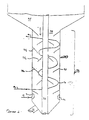
- FIG. 2 is a simplified schematic diagram showing an FCC unit reactor riser and spent catalyst stripper including the novel catalyst stripper design of the present invention.
- a hydrocarbon oil feed such as gas oil or higher boiling material is introduced through a conduit 2 to the bottom or upstream section of a riser reactor 70.
- Hot regenerated catalyst is also introduced to the bottom section of the riser by a standpipe 6 equipped with a flow control valve 8.
- a vapor liquid suspension is formed in the lower bottom section of the riser 70 at an elevated temperature at 525°C to 650°C (980°F to 1200°F) and is usually at least 540°C (1000°F), depending on the degree of hydrocarbon conversion desired and on the composition of the feed.
- the suspension is formed in the bottom section of the riser and is passed upwardly through the riser under selected temperature and residence time conditions.
- Residence of the hydrocarbon charge stock in the riser is usually between 0.1 and 15 seconds, typically 0.5 to 4 seconds, before the suspension passes through suitable separating means, such as a series of cyclones 11 rapidly effecting separation of catalyst particles from vapor hydrocarbon conversion products.
- suitable separating means such as a series of cyclones 11 rapidly effecting separation of catalyst particles from vapor hydrocarbon conversion products.
- the suspension is discharged from the riser 70 into one or more cyclonic separators attached to the end of the riser and represented by a separator means 11.
- Catalyst particles separated in the cyclone 11 pass countercurrently in contact with stripping gas introduced by conduit 16 to a lower portion of the cyclone.
- the contacted and separated catalyst is withdrawn by a dipleg 14 for discharge into a bed of catalyst in the lower section of the reactor.
- the end of the riser 70 with attached separation means 11 as shown in Figure 1 is housed in the larger vessel 17 designated herein as a receiving and catalyst collecting vessel.
- the lower portion of the vessel 17 has generally a smaller diameter than the upper portion thereof and comprises a catalyst stripping section 73 to which a suitable stripping gas, such as steam, is introduced, e.g. by a conduit 75.
- the stripping section is provided with a plurality of frustoconical baffles 74A, 74B and 74C (only three are designated) over which the downflowing catalyst passes countercurrently to upflowing stripping gas.
- Hot flue gas is withdrawn from plenum section 58 of regenerator vessel 36 through conduit 60.
- Control valve 90 positioned in line 80 sets the flowrate of hot flue gas flowing from the regenerator vessel 36 to the stripping section 73.
- Hot regenerated catalyst is withdrawn from the regenerator vessel 36 through line 100 which is equipped with control valve 101 and flows into line 80 where it is fluidized in a stream of hot flue gas.
- the fluidized mixture flows through line 80 into heat exchanger conduit 76 positioned inside the stripping section 73. While line 80 is illustrated as entering stripping section 73 near the top, it is to be understood that the present invention encompasses both downflow and upflow embodiments. Consequently, line 80 may alternatively be positioned near the bottom of stripper section 73.
- a compressor 85 may optionally be installed in line 80 to facilitate flow of flue gas and fluidized catalyst through line 81 into standpipe 6.
- the conduit means may comprise a heat exchanger conduit 76 passing helically between the baffles, or the conduit may comprise a plurality of vertical or horizontal tubes (not shown).
- the fluidized mixture of flue gas and regenerated catalyst enters the heat exchanger conduit 76 at between 650°C and 760°C (1200°F and 1400°F) and leaves the stripping section at a temperature between 590°C and 710°C (1100°F and 1300°F).
- the cooled fluidized mixture from heat exchanger conduit 76 flowing through line 81 flows into regenerated catalyst standpipe 6.
- the cooled fluidized mixture may be returned to the regenerator.
- line 80 is positioned near the bottom for upflow operation, then line 81 will be positioned near the top of stripper section 73.
- Regenerated catalyst and flue gas flow-rates are controlled to increase the temperature in the stripper section 73 sufficiently to achieve enhanced separation between catalyst and reaction products in the stripper. This temperature increase should exceed 28°C (50°F).
- a cyclone 24 is provided in the upper portion of the vessel 16 for recovering stripped hydrocarbon products and stripping gas from entrained catalyst particles.
- a second sequential stage (not shown) of catalyst separation for product vapors discharged from the separator 11 by a conduit 26.
- Deactivated stripped catalyst is withdrawn from the bottom of the stripping section at an elevated temperature which may vary with individual unit operation but typically ranges between 560°C and 600°C (1050°F to 1100°F), by a standpipe 72 equipped with a flow control valve 32.
- the catalyst is then passed from the standpipe 72 into the bottom portion of a regenerator riser 34.
- a regeneration gas is introduced into the bottom of riser 34 through a conduit 35.
- the regeneration gas may comprise air or may optionally comprise preheated air or oxygen supplemented air at 150°C to 260°C (300°F to 500°F) and 270 kPa (25 psig) to 450 kPa (50 psig), typically 380 kPa (40 psig).
- regenerator vessel 36 comprises a bottom closure member 38 shown in the drawing to be conical in shape. Other suitable shapes obvious to those skilled in the art may also be employed, such as rounded dish shapes.
- the regenerator vessel 36 comprises a smaller diameter cylindrical vessel means 40 in the lower section provided with a cyclindrical bottom containing a cyclindrical opening, whose cross section is at least equal to the cross section of the riser 34.
- An annular space 49 is formed by the chambers 36 and 40 and serves to recirculate regenerated catalyst to the dense bed.
- Vessel 40 is provided with a conical head member 46 terminating in a relatively short cylindrical section of sufficient vertical height capped at its upper end by means 47 to accommodate a plurality of radiating arm means 48.
- the radiating arm means 48 are opened on the bottom side and operate to discharge a concentrated stream of catalyst substantially separated from the combustion product gases generally downward into the space 49.
- a plurality of cyclonic separators 54 and 56 is provided for separating combustion flue gas from entrained catalyst particles.
- the separated flue gas passes into plenum 58 for withdrawal by a conduit 60.
- a controlled amount of flue gas is routed to the catalyst stripper section 73 through conduit 80 as described above.
- the balance of the flue gas is sent to a heat recovery section, e.g. steam generation, through conduit 96.
- the illustrated catalyst regenerator operation is designed to provide regenerated catalyst at an elevated temperature above 232°C (450°F) and preferably at 704°C to 816°C (1300°F to 1500°F) having residual coke on catalyst of less than 0.15 and typically 0.1 to 0.01 weight percent.
- the process of the present invention can be successfully used with any regenerator coupled to an FCC reactor. Accordingly, the regenerator operation illustrated in the embodiment of Figure 1 is used as an example of one suitable regenerator and is not to be considered a limitation of the present invention.
- FIG. 2 details the catalyst stripper section of reactor vessel 17 shown in Figure 1.
- the catalyst stripper section 73 comprises a cylindrical longitudinally extensive outer shell 93 having a plurality of frustoconical members 74A and 74B (only two are designated) attached to the inner surface thereof.
- Riser conduit 70 extends longitudinally through the stripper section and is equipped with a plurality of frustoconical members 74C (only one is designated) attached to its outside surface.
- a mixture of deactivated catalyst and entrained catalytically cracked product flows downward from a dense bed 95 to the inlet 94 of the catalyst stripper.
- Steam is introduced to the catalyst stripper near the bottom through conduit 75 and perforated steam distribution ring 71. Steam flows upward around the frustoconical baffles, stripping catalytically cracked product off the deactivated catalyst.
- the catalyst flows downward through the catalyst stripper and exits through valved standpipe 72.
- Conduit 80 may join a single heat exchanger conduit 76 which winds through the frustoconical baffles 74A, 74B and 74C.
- the cooled mixture of flue gas and regenerated catalyst leaves the heat exchanger conduit and flows to the regenerated catalyst standpipe 6 through conduit 81.
- conduit 80 may be joined with a plurality of vertical or horizontal tubes resembling a heat exchanger bank. The cooled mixture of flue gas and regenerated catalyst flowing out of the tubes is consolidated and similarly leaves the catalyst stripper through conduit 81.
Landscapes
- Chemical & Material Sciences (AREA)
- Oil, Petroleum & Natural Gas (AREA)
- Engineering & Computer Science (AREA)
- Chemical Kinetics & Catalysis (AREA)
- General Chemical & Material Sciences (AREA)
- Organic Chemistry (AREA)
- Production Of Liquid Hydrocarbon Mixture For Refining Petroleum (AREA)
Claims (5)
- Katalytisches Wirbelschichtcrackverfahren in einem Riser-Reaktor, welches die Schritte umfaßt:(a) Vermischen einer Kohlenwasserstoffbeschickung mit heißem regeneriertem Crackkatalysator im unteren Abschnitt eines im wesentlichen senkrechten Riser-Reaktors, um im unteren Abschnitt dieses Riser-Reaktors bei einer Temperatur von 525 bis 650°C eine Dampf/Flüssigkeits-Suspension zu bilden;(b) Leiten der Mischung vom Schritt (a) nach oben durch den Riser-Reaktor bei ausgewählten Bedingungen für Temperatur und Verweilzeit, um zumindest einen Teil der Kohlenwasserstoffbeschickung katalytisch zu cracken, wodurch der Crackkatalysator deaktiviert wird;(c) Strömung der Mischung vom Schritt (b) durch die Trenneinrichtung, um die Abtrennung der Katalysatorpartikel von den Produkten der Kohlenwasserstoffumwandlung durchzuführen;(d) Abtrennen des Kohlenwasserstoffs von den abgetrennten deaktivierten Katalysatorpartikeln vom Schritt (c) durch Kontakt der Katalysatorpartikel mit dem Trenngas im Gegenstrom in einer ringförmigen Trennzone; wobei diese ringförmige Trennzone mit dem unteren Abschnitt des Riser-Reaktors konzentrisch ist;(e) Abziehen des abgetrennten deaktivierten Katalysators aus der ringförmigen Trennzone vom Schritt (d);(f) Regenerierung des abgezogenen deaktivierten Katalysators vom Schritt (e) in einer Regenerierungszone, die vom Riser-Reaktor entfernt ist und damit über Ventile verbunden ist, bei einer Temperatur oberhalb der der Trennzone, wodurch ein heißes Abgas erzeugt wird;(g) Abziehen eines geregelten Volumens des heißen regenerierten Crackkatalysators vom unteren Abschnitt der Regenerierungszone;(h) Verwirbelung des heißen regenerierten Crackkatalysators vom Schritt (g) in einem Strom des heißen Abgases, der aus der Regenerierungszone vom Schritt (f) abgezogen wurde; und(i) indirekte Übertragung von zumindest einem Teil der Wärmeenergie der verwirbelten Mischung vom Schritt (h) zur Trennzone vom Schritt (d), um die Trennzone vom Schritt (d) zu erwärmen und die verwirbelte Mischung des regenerierten Crackkatalysators und des Abgases des Regenerators abzukühlen.
- Verfahren nach Anspruch 1, worin der Schritt (i), der zumindest einen Teil der Wärmeenergie der verwirbelten Mischung vom Schritt (h) indirekt zur Trennzone vom Schritt (d) überträgt, außerdem die Anordnung einer Leitung innerhalb der Trennzone vom Schritt (d) und das Strömen der verwirbelten Mischung vom Schritt (h) durch diese Leitung umfaßt.
- Verfahren nach Anspruch 2, das außerdem die Regelung der Strömung der Mischung aus heißem Abgas und regeneriertem Katalysator durch die Leitung bei einer solchen Strömungsgeschwindigkeit umfaßt, daß die Trennzone vom Schritt (d) auf eine ausreichende Temperatur erwärmt wird, um die Abtrennung von Katalysator und Kohlenwasserstoffprodukt zu verbessern.
- Verfahren nach Anspruch 3, worin die Strömung der Mischung aus heißem Abgas und regeneriertem Katalysator geregelt wird, um die Temperatur der Trennzone um mindestens 28°C (50°F) zu erhöhen.
- Verfahren nach Anspruch 1, das außerdem das Strömen der abgekühlten verwirbelten Mischung des regenerierten Crackkatalysators und des Abgases des Regenerators zum Riser-Reaktor vom Schritt (a) umfaßt.
Priority Applications (1)
| Application Number | Priority Date | Filing Date | Title |
|---|---|---|---|
| DE1989608714 DE68908714T2 (de) | 1989-12-20 | 1989-12-20 | Verfahren für das Strippen von verbrauchtem FCC-Katalysator. |
Applications Claiming Priority (1)
| Application Number | Priority Date | Filing Date | Title |
|---|---|---|---|
| US07/198,263 US4973398A (en) | 1988-05-25 | 1988-05-25 | Method of FCC spent catalyst stripping for improved efficiency and reduced hydrocarbon flow to regenerator |
Publications (2)
| Publication Number | Publication Date |
|---|---|
| EP0433504A1 EP0433504A1 (de) | 1991-06-26 |
| EP0433504B1 true EP0433504B1 (de) | 1993-08-25 |
Family
ID=22732650
Family Applications (1)
| Application Number | Title | Priority Date | Filing Date |
|---|---|---|---|
| EP89313387A Expired - Lifetime EP0433504B1 (de) | 1988-05-25 | 1989-12-20 | Verfahren für das Strippen von verbrauchtem FCC-Katalysator |
Country Status (4)
| Country | Link |
|---|---|
| US (1) | US4973398A (de) |
| EP (1) | EP0433504B1 (de) |
| JP (1) | JPH03199292A (de) |
| AU (1) | AU617572B2 (de) |
Families Citing this family (4)
| Publication number | Priority date | Publication date | Assignee | Title |
|---|---|---|---|---|
| US5062945A (en) * | 1988-09-23 | 1991-11-05 | Mobil Oil Corporation | Method of FCC spent catalyst stripping for improved efficiency and reduced hydrocarbon flow to regenerator |
| JPH06505517A (ja) * | 1991-03-05 | 1994-06-23 | エクソン・リサーチ・アンド・エンヂニアリング・カンパニー | 接触分解方法および装置 |
| WO2010036499A2 (en) * | 2008-09-25 | 2010-04-01 | Uop Llc | Stripping process and apparatus with multi-sloped baffles |
| US12233405B2 (en) | 2019-07-31 | 2025-02-25 | Sabic Global Technologies B.V. | Heating plates riser reactor |
Family Cites Families (23)
| Publication number | Priority date | Publication date | Assignee | Title |
|---|---|---|---|---|
| US2735822A (en) * | 1956-02-21 | Method of and apparatus for contacting solids and gases | ||
| US2619473A (en) * | 1946-05-14 | 1952-11-25 | Standard Oil Dev Co | Method and apparatus for regenerating a fluidized catalyst |
| US2684931A (en) * | 1949-08-20 | 1954-07-27 | Union Oil Co | Fluidized solids process for contacting solids and vapors with the conveyance of the solids in dense phase suspension |
| US2696461A (en) * | 1950-11-30 | 1954-12-07 | Kellogg M W Co | Regeneration of hydrocarbon conversion catalysts |
| US2788311A (en) * | 1951-08-03 | 1957-04-09 | Kellogg M W Co | Fluid system |
| US2728642A (en) * | 1952-06-09 | 1955-12-27 | Tide Water Associated Oil Comp | Gas-solids contacting apparatus |
| US2926133A (en) * | 1956-02-29 | 1960-02-23 | Kellogg M W Co | Process and apparatus for conducting catalytic reactions and stripping |
| US3008896A (en) * | 1959-09-21 | 1961-11-14 | Phillips Petroleum Co | Catalytic cracking of residual oils |
| US3392110A (en) * | 1965-09-02 | 1968-07-09 | Mobil Oil Corp | Method for the utilization of highly active hydrocarbon conversion catalysts |
| AT364745B (de) * | 1975-03-24 | 1981-11-10 | Ashland Oil Inc | Verfahren und vorrichtung zum abscheiden feiner feststoffteilchen aus stroemenden gasen |
| US4043899A (en) * | 1976-02-27 | 1977-08-23 | Mobil Oil Corporation | Method and means for separating gasiform materials from finely divided catalyst particles |
| US4332674A (en) * | 1980-07-15 | 1982-06-01 | Dean Robert R | Method and apparatus for cracking residual oils |
| US4411773A (en) * | 1980-12-18 | 1983-10-25 | Mobil Oil Corporation | Heat balance in FCC process and apparatus with downflow reactor riser |
| US4356082A (en) * | 1980-12-18 | 1982-10-26 | Mobil Oil Corporation | Heat balance in FCC process |
| US4464250A (en) * | 1981-07-30 | 1984-08-07 | Ashland Oil, Inc. | Stripping hydrocarbons from catalyst with combustion gases |
| US4419221A (en) * | 1981-10-27 | 1983-12-06 | Texaco Inc. | Cracking with short contact time and high temperatures |
| US4424116A (en) * | 1982-03-25 | 1984-01-03 | Ashland Oil, Inc. | Converting and stripping heavy hydrocarbons in two stages of riser conversion with regenerated catalyst |
| US4574044A (en) * | 1982-03-31 | 1986-03-04 | Chevron Research Company | Method for spent catalyst treating for fluidized catalytic cracking systems |
| US4404095A (en) * | 1982-07-22 | 1983-09-13 | Mobil Oil Corporation | Method and means for separating gaseous materials from finely divided catalyst particles |
| US4786622A (en) * | 1984-01-09 | 1988-11-22 | Ashland Oil, Inc. | Regeneration of fluid solid particles and separation of solid particles from combustion product flue gases |
| US4689206A (en) * | 1984-10-22 | 1987-08-25 | Mobil Oil Corporation | Multistage stripper for FCC unit with improved catalyst separation |
| FR2574422B1 (fr) * | 1984-12-07 | 1988-01-08 | Raffinage Cie Francaise | Perfectionnements aux procedes et dispositifs pour le craquage catalytique a l'etat fluide de charges d'hydrocarbures |
| US4724065A (en) * | 1985-12-05 | 1988-02-09 | Engelhard Corporation | Hydrocarbon conversion with hot and cooled regenerated catalyst in series |
-
1988
- 1988-05-25 US US07/198,263 patent/US4973398A/en not_active Expired - Fee Related
-
1989
- 1989-12-20 EP EP89313387A patent/EP0433504B1/de not_active Expired - Lifetime
- 1989-12-27 JP JP1345085A patent/JPH03199292A/ja active Pending
-
1990
- 1990-01-05 AU AU47728/90A patent/AU617572B2/en not_active Ceased
Also Published As
| Publication number | Publication date |
|---|---|
| AU617572B2 (en) | 1991-11-28 |
| EP0433504A1 (de) | 1991-06-26 |
| JPH03199292A (ja) | 1991-08-30 |
| US4973398A (en) | 1990-11-27 |
| AU4772890A (en) | 1991-07-11 |
Similar Documents
| Publication | Publication Date | Title |
|---|---|---|
| US5062945A (en) | Method of FCC spent catalyst stripping for improved efficiency and reduced hydrocarbon flow to regenerator | |
| US4219407A (en) | Fluid cracking process and the method for separating a suspension discharged from a riser cracking zone | |
| US4411773A (en) | Heat balance in FCC process and apparatus with downflow reactor riser | |
| JP2523325B2 (ja) | 新規な下降流の流動化接触分解反応器 | |
| JP4671089B2 (ja) | 少なくとも1つのライザー反応器と、少なくとも1つのドロッパー反応器とを並列状に含む接触クラッキング方法および装置 | |
| EP0086580B1 (de) | Verfahren und Vorrichtung zum flüssigen katalytischen Cracken | |
| US4478708A (en) | Method and apparatus for separating fluidized solid particles suspended in gasiform material | |
| US4404095A (en) | Method and means for separating gaseous materials from finely divided catalyst particles | |
| US5589139A (en) | Downflow FCC reaction arrangement with upflow regeneration | |
| EP0643122B1 (de) | Vorrichtung zum Ausscheiden von Suspensionen von Katalysatorteilchen und Kohlenwasserstoffreaktionsmischung und ein katalytisches Krackverfahren | |
| US4623446A (en) | Closed cyclone FCC catalyst separation with stripping gas injection and direct steam injection | |
| US4356082A (en) | Heat balance in FCC process | |
| US4118338A (en) | Method for regenerating a fluid cracking catalyst | |
| US4786622A (en) | Regeneration of fluid solid particles and separation of solid particles from combustion product flue gases | |
| US5112576A (en) | Catalytic cracking unit with combined catalyst separator and stripper | |
| US3433733A (en) | Method and apparatus for fluid catalytic cracking | |
| US5158669A (en) | Disengager stripper | |
| US7799286B2 (en) | Stripping apparatus | |
| US4971681A (en) | Method and apparatus for improved FCC spent catalyst stripping | |
| US7914610B2 (en) | Stripping process | |
| US4973398A (en) | Method of FCC spent catalyst stripping for improved efficiency and reduced hydrocarbon flow to regenerator | |
| US5376339A (en) | Direct-coupled FCC riser cyclone and plenum | |
| US5308474A (en) | Plug flow vented riser | |
| US20090107884A1 (en) | Stripping apparatus and process | |
| US5316662A (en) | Integrated disengager stripper and its use in fluidized catalytic cracking process |
Legal Events
| Date | Code | Title | Description |
|---|---|---|---|
| PUAI | Public reference made under article 153(3) epc to a published international application that has entered the european phase |
Free format text: ORIGINAL CODE: 0009012 |
|
| 17P | Request for examination filed |
Effective date: 19901229 |
|
| AK | Designated contracting states |
Kind code of ref document: A1 Designated state(s): BE DE FR GB IT NL |
|
| 17Q | First examination report despatched |
Effective date: 19920313 |
|
| GRAA | (expected) grant |
Free format text: ORIGINAL CODE: 0009210 |
|
| AK | Designated contracting states |
Kind code of ref document: B1 Designated state(s): BE DE FR GB IT NL |
|
| ET | Fr: translation filed | ||
| REF | Corresponds to: |
Ref document number: 68908714 Country of ref document: DE Date of ref document: 19930930 |
|
| ITF | It: translation for a ep patent filed | ||
| PLBE | No opposition filed within time limit |
Free format text: ORIGINAL CODE: 0009261 |
|
| STAA | Information on the status of an ep patent application or granted ep patent |
Free format text: STATUS: NO OPPOSITION FILED WITHIN TIME LIMIT |
|
| 26N | No opposition filed | ||
| PGFP | Annual fee paid to national office [announced via postgrant information from national office to epo] |
Ref country code: FR Payment date: 19981202 Year of fee payment: 10 |
|
| PGFP | Annual fee paid to national office [announced via postgrant information from national office to epo] |
Ref country code: GB Payment date: 19981203 Year of fee payment: 10 |
|
| PGFP | Annual fee paid to national office [announced via postgrant information from national office to epo] |
Ref country code: DE Payment date: 19981204 Year of fee payment: 10 |
|
| PGFP | Annual fee paid to national office [announced via postgrant information from national office to epo] |
Ref country code: NL Payment date: 19981217 Year of fee payment: 10 |
|
| PGFP | Annual fee paid to national office [announced via postgrant information from national office to epo] |
Ref country code: BE Payment date: 19981231 Year of fee payment: 10 |
|
| PG25 | Lapsed in a contracting state [announced via postgrant information from national office to epo] |
Ref country code: GB Free format text: LAPSE BECAUSE OF NON-PAYMENT OF DUE FEES Effective date: 19991220 |
|
| PG25 | Lapsed in a contracting state [announced via postgrant information from national office to epo] |
Ref country code: BE Free format text: LAPSE BECAUSE OF NON-PAYMENT OF DUE FEES Effective date: 19991231 |
|
| BERE | Be: lapsed |
Owner name: MOBIL OIL CORP. Effective date: 19991231 |
|
| PG25 | Lapsed in a contracting state [announced via postgrant information from national office to epo] |
Ref country code: NL Free format text: LAPSE BECAUSE OF NON-PAYMENT OF DUE FEES Effective date: 20000701 |
|
| GBPC | Gb: european patent ceased through non-payment of renewal fee |
Effective date: 19991220 |
|
| PG25 | Lapsed in a contracting state [announced via postgrant information from national office to epo] |
Ref country code: FR Free format text: LAPSE BECAUSE OF NON-PAYMENT OF DUE FEES Effective date: 20000831 |
|
| NLV4 | Nl: lapsed or anulled due to non-payment of the annual fee |
Effective date: 20000701 |
|
| PG25 | Lapsed in a contracting state [announced via postgrant information from national office to epo] |
Ref country code: DE Free format text: LAPSE BECAUSE OF NON-PAYMENT OF DUE FEES Effective date: 20001003 |
|
| REG | Reference to a national code |
Ref country code: FR Ref legal event code: ST |
|
| PG25 | Lapsed in a contracting state [announced via postgrant information from national office to epo] |
Ref country code: IT Free format text: LAPSE BECAUSE OF NON-PAYMENT OF DUE FEES;WARNING: LAPSES OF ITALIAN PATENTS WITH EFFECTIVE DATE BEFORE 2007 MAY HAVE OCCURRED AT ANY TIME BEFORE 2007. THE CORRECT EFFECTIVE DATE MAY BE DIFFERENT FROM THE ONE RECORDED. Effective date: 20051220 |