EP0433439B1 - Vacuum cleaner with a particular mounting structure for disposable dust bags - Google Patents
Vacuum cleaner with a particular mounting structure for disposable dust bags Download PDFInfo
- Publication number
- EP0433439B1 EP0433439B1 EP90911721A EP90911721A EP0433439B1 EP 0433439 B1 EP0433439 B1 EP 0433439B1 EP 90911721 A EP90911721 A EP 90911721A EP 90911721 A EP90911721 A EP 90911721A EP 0433439 B1 EP0433439 B1 EP 0433439B1
- Authority
- EP
- European Patent Office
- Prior art keywords
- connector
- vacuum cleaner
- adaptor
- bag
- cleaner according
- Prior art date
- Legal status (The legal status is an assumption and is not a legal conclusion. Google has not performed a legal analysis and makes no representation as to the accuracy of the status listed.)
- Expired - Lifetime
Links
Images


Classifications
-
- A—HUMAN NECESSITIES
- A47—FURNITURE; DOMESTIC ARTICLES OR APPLIANCES; COFFEE MILLS; SPICE MILLS; SUCTION CLEANERS IN GENERAL
- A47L—DOMESTIC WASHING OR CLEANING; SUCTION CLEANERS IN GENERAL
- A47L9/00—Details or accessories of suction cleaners, e.g. mechanical means for controlling the suction or for effecting pulsating action; Storing devices specially adapted to suction cleaners or parts thereof; Carrying-vehicles specially adapted for suction cleaners
- A47L9/10—Filters; Dust separators; Dust removal; Automatic exchange of filters
- A47L9/14—Bags or the like; Rigid filtering receptacles; Attachment of, or closures for, bags or receptacles
- A47L9/1427—Means for mounting or attaching bags or filtering receptacles in suction cleaners; Adapters
- A47L9/1436—Connecting plates, e.g. collars, end closures
Definitions
- This invention relates to a vacuum cleaner
- the bags are only used once and are discarded when full of dirt and dust, they must be economical to produce and market. However, the bags must be sufficiently durable to permit them to be installed and removed without damage. They must also provide a connecting and sealing structure for connecting the bag to the dirt-laden air discharge of the cleaner which is easily installed and which provides a reliable seal so that all of the dirt-laden air enters the filter bag.
- Examples of disposable dust bag mounting systems are illustrated in United States Letters Patent Nos. 2,975,862; 3,150,405; 3,933,451; and 4,274,847.
- the latter of such patents disclose a mounting structure providing a rigid cardboard or plastic collar and a plastic diaphragm secured to the body of the dust bag around the inlet opening therein.
- the collar is provided with an opening having an enlarged portion which is sized to pass over a rib which extends around the end of the vacuum cleaner coupling.
- the collar opening also provides a portion of reduced size which fits behind the rib when the collar is shifted laterally to the mounted position. Because of the shifting movement required, the collar must be relatively large. Also, because the diaphragm tends to lock the collar in the mounted position, the removal of the bag after use can be difficult.
- US-A-4 262 384 discloses a vacuum cleaner with an adaptor for sealingly mounting disposable dust bags in fluid communication with a connector.
- the adaptor is fixed by a hinge to a structure carrying the connector and the communication between dust bag and connector is obtained by pivoting the adaptor carrying the dust bag untill the end of the adaptor engages by force a suitable part of said structure.
- the present invention provides a vacuum cleaner as claimed in claim 1 and dependant claims 2 to 20.
- the mounting system provides a low cost structure which is easily mounted and removed and which reliably provides a strong connection and a reliable seal.
- a vacuum cleaner connector has a generally cylindrical wall extending to an open end through which dirt-laden air is discharged by the vacuum cleaner fan. Peripherally spaced projections extend from the wall substantially adjacent to the open end thereof.
- the dust bag is provided with a substantially rigid collar and an elastomeric diaphragm. The collar provides an opening therein having portions of reduced diameter sized to closely fit the outer surface of the connector wall and enlarged peripherally spaced portions sized to pass back and forth past the connector projections when the bag is in a mounting and removal position.
- the collar is moved onto the connector, with the connector projections aligned with the enlarged portions of the collar opening, and is then rotated relative to the connector, causing the portions of reduced diameter to move in behind the connector projections to securely lock the collar on the connector. Removal of the bag is accomplished by reversing the direction of rotation back to the mounting and removal position, after which the bag is removed.
- the elastomeric diaphragm is provided with a centrally located opening having a diameter substantially smaller than the end of the coupling, and is adhesively secured to the collar entirely around the collar opening.
- the collar is formed of two layers of stiff cardboard with a diaphragm sandwiched therebetween.
- the diaphragm As the collar is pressed past the connector projections, the diaphragm is stretched over the projections and the collar is rotated to the locked position. When in the locked position, the diaphragm stretches outwardly along the back side of the projections and extends forwardly over the projections and then inwardly along the forward face of the projections. This engagement between the diaphragm and the projections provides a tight fit and ensures that during use the collar remains in the locked position.
- the opening in the diaphragm is initially sized so that the diaphragm extends inwardly along a substantial portion of the end of the connector wall with a tight fit.
- the diaphragm provides an effective lip seal which prevents air pressure within the bag from causing leakage back along the exterior of the coupling.
- the lip seal is also provided along any portions of the diaphragm which extend back along the outer cylindrical surface of the coupling so that a reliable seal is provided.
- the bag itself is a vertically extending, elongated bag, and the inlet is spaced both from the upper and lower ends of the bag.
- the dirt and dust collect within the bag it tends to collect within the lower portion below the inlet leaving the upper portion of the bag substantially clear so that the air can pass out of the bag without developing a high back pressure which would substantially decrease the effectiveness of the cleaner.
- the bag, with the dirt therein is removed and discarded so that a new, empty bag can be installed.
- the adaptor is capable of being installed on the connector by the user of the vacuum cleaner without tools or separate fasteners. Once installed, the adaptor can remain on the connector indefinitely while disposable bags, once used, are removed and replaced periodically.
- the adaptor, as disclosed, can take a variety of styles, shapes and manner of attachment to the connector.
- FIG. 1 schematically illustrates a disposable dust bag and mounting system as known applied to a typical upright vacuum cleaner 10.
- the vacuum cleaner 10 includes a motor and fan housing assembly 11.
- Such cleaners are particularly adapted for carpet and rug cleaning, and in many instances can be provided with various types of attachments for other types of cleaning operations.
- Dirt-laden air is discharged by the fan through a flexible hose 12 which extends upwardly from the housing assembly 11 within a cloth dust bag 13.
- the dust bag 13 is connected at 14 to the housing assembly 11, and is supported at its upper end from the handle 16 of the vacuum cleaner.
- a disposable dust bag 17 incorporating the present invention is installed during use within the cloth dust bag 13. Normally, the cloth dust bag 13 is provided with a zipper 18 which can be opened to provide access for the mounting and removal of the disposable dust bag 17.
- a connector 19 which is connected to the disposable dust bag 17, as described in greater detail below, and through which dirt-laden air passes into the disposable dust bag 17.
- the dust bag 17 is provided with a mounting collar 21 which is removably mounted to the connector 19 so that all of the dirt-laden air from the cleaner enters the dust bag where the dirt is collected.
- the connector 19 and the mounting collar of the disposable dust bag 17 is best illustrated in FIG. 2.
- the connector 19, in the illustrated embodiment, is a molded plastic part providing a generally cylindrical inlet 22 connected by suitable means to the flexible hose 12.
- the dirt-laden air enters the connector 19 through the inlet 22 of the connector 19 and is discharged through a generally cylindrical outlet portion 23, which in the illustrated embodiment extends at right angles to the inlet 22.
- the connector is provided with a pair of peripherally spaced mounting projections 26 and 27, which cooperate with the collar to securely mount the collar on the connector 19 when the dust bag 17 is mounted thereon.
- the rearward walls 26a and 27a of the projections 16 and 27, respectively, extend radially and the forward walls are inclined.
- the mounting collar 21, in the illustrated embodiment, includes two layers 31 and 32 of stiff, substantially rigid cardboard, which are laminated with adhesive to opposite sides of an elastomeric diaphragm 33.
- the layer of cardboard 31 is also adhesively secured to the wall 34 of the disposable dust bag around the inlet 35 therein.
- the dust bag is formed of an air-permeable paper material of the general type used in the past to form disposable dust bags for vacuum cleaners and the like, and is folded and seamed to define an elongated bag structure which defines a chamber 35a in which the dirt is collected.
- the mounting collar 21 is located at a location spaced from the upper end 36 and the lower end 37 of the dust bag.
- the dirt-laden air enters the bag from the connector 19 through the inlet 35, and the material forming the bag allows the air to pass out through the bag 17 and the cloth dust bag 13 to the environment while preventing the passage of the particles of dirt entrained within the air.
- Such dirt tends to collect in the lower part of the bag and because the inlet is spaced from the upper end 36 of the bag, the upper portion of the bag remains relatively clear of collected dirt so that substantially free passage of the air occurs from the dust bag.
- the dust bag is removed and discarded along with the dirt collected therein when the level of the dirt approaches the level of the inlet at the mounting collar.
- the two layers 31 and 32 of the mounting collar 21 are formed with identical openings 41 therein and the diaphragm 33 is formed with a circular opening 42 which is substantially smaller than the openings 41 in the two collar layers 31 and 32.
- the openings 41 are circular, except for two radially extending, enlarged portions 43 and 44, which are sized and positioned to clear the projections 26 and 27 when the collar is installed on and removed from the connector 19.
- the projections 26 and 27 are located on the top and bottom of the outlet portion of the connector 19 and the enlarged portions 43 and 44 are oriented with respect to the length of the bag at about 45 degrees.
- the collar is oriented in an angled position in which the two enlarged portions 43 and 44 are aligned with the mounting projections 26 and 27, respectively, as best illustrated in FIGS. 3 and 3a. This is the mounting and removal position of the collar 21 with respect to the connector 19. In such position, the collar 21 is initially moved to the position illustrated in FIG. 3a, in which the diaphragm 33 engages the end 24 of the connector 19, and the circular portions 40 of the opening 41 in the two layers 31 and 32 align with and closely fit the exterior surface of the outlet portion 23 of the connector. Further, the projections 26 and 27 are aligned with the enlarged portions 43 and 44, respectively.
- the mounting collar 21 is pushed from the full-line position illustrated in FIG. 3a to the phantom-line position, in which the collar extends behind the projections 26 and 27.
- the collar is then rotated relative to the connector 19 to the fully mounted position illustrated in FIGS. 4 and 4a. In such position, the circular portions 40 of the collar are positioned behind the two projections 26 and 27, engaging the rearward walls 26a and 27a. Therefore, the collar is locked onto the connector.
- the diaphragm opening 42 is substantially smaller than the end of the connector 19 so that as the mounting collar is pressed over the end of the connector 19, the diaphragm is stretched to the position illustrated in FIG. 4a, in which the diaphragm extends outwardly along the rearward sides 26a and 26b of the adjacent projections 26 and 27 and inwardly along the forward side of each projection.
- the projection 26 is spaced back from the end 24 of the connector 19 and the projection 27 is substantially adjacent thereto. Consequently, the collar in its mounted position is inclined to some extent with respect to a plane perpendicular to the outlet portion 36.
- the diaphragm is stretched around the exterior wall of the outlet portion 23 and also extends in along the end 24 of the connector 19.
- the diaphragm along that portion of the connector extends inwardly a small distance beyond the end 24 but, adjacent to the projection 26, the diaphragm engages the end 24 to a lesser extent.
- this engagement between the diaphragm and the exterior wall of the connector 19 and along the end 24 thereof provides a lip seal which ensures that a fluidtight joint is provided between the disposable dust bag 17 and the connector. This ensures that all of the dirt-laden air passes into the disposable dust bag and that no leakage occurs.
- the opening 42 in the diaphragm substantially smaller than the end 24 of the connector it is ensured that the diaphragm maintains this lip seal and does not blow through and invert during the operation of the cleaner.
- the diaphragm provides a very snug mechanical contact with the end of the connector which frictionally maintains the dust bag in its mounted position and during the use of the cleaner.
- the dust bag When the level of dirt collected in the dust bag reaches substantially to the level of the inlet provided by the mounting ring, the dust bag is rotated in the opposite direction to again bring the enlarged portions 43 and 44 into alignment with the associated projections 26 and 27 and the dust bag is easily removed from the connector for disposal. Subsequently, a new, empty disposable dust bag is installed and cleaning operations can be continued.
- the face of the collar is provided with printed indicia 45 to indicate the proper position for the mounting of the dust bag on the collar and for its removal.
- a low-cost, reliable structure which can be easily installed and removed by the user, and which ensures that a good seal is provided between the dust bag and the connector.
- the connector 50 illustrated in FIGS. 5 - 7 has the same general configuration as that shown in the earlier FIGS. 1 - 4 with the major difference being the addition of a peripheral flange 51 and the mounting collar 21 of the bag 17 is mountable directly on this connector 50.
- the connector has the shape of a tubular el of round cross-section.
- the connector 50 is a thin walled injection molded plastic body of suitable material such as copolymer polypropylene.
- a lower vertical end 52 of the connector 50 is received in the flexible hose 12 in the same manner as the previously described connector 19.
- the connector 50 receives dirty air, delivered from the fan of the vacuum cleaner 10 through the hose 12.
- An upper horizontal end 53 forms the outlet of the connector 50.
- the outlet end 53 includes a circular nipple portion 54 from which the flange 51 projects.
- the exterior of the nipple portion 54 has a peripheral radially extending rib 56 (FIG. 6a) formed through the existence of an immediately adjacent peripheral groove 57.
- a pair of diametrically opposite projections rise radially above the circular periphery of the nipple portion 54 and lying in a common radial plane.
- the projections 58 are substantially identical, each having a circumferential length substantially less than the circumference of the nipple portion 54.
- the projections 58 have a limited radial extent beyond the adjacent circular areas of the nipple 54 and project radially from this nipple portion to a lesser degree than does the flange 51.
- the projections 58 include walls or surfaces 59 which face rearwardly away from an end face or terminus 60 of the nipple portion 54.
- the base of the flange 51 where it meets the periphery of the circular nipple portion 54, is spaced axially inward from the projections 58 at least a distance corresponding to the thickness of a mounting collar 61 of a disposable bag assembly 62.
- the flange 51 is dished so that it is concave on a face 63 adjacent the nipple end 60 and its radially outer periphery 64 is closely adjacent the radial plane common to the projections 58.
- the exterior of the connector inward or upstream of the flange 51 is relatively smooth and circular, being devoid of any significant surface formations or extensions except for a vertical bracket 66 from which the connector 50 is suspended and small circumferentially extending spaced ribs 67 that help anchor the hose 12 to the inlet 52.
- a disposable bag assembly 62 shown fragmentarily in FIGS. 5 - 7 is of generally known construction.
- the bag assembly 62 comprises foldable porous sheet material 69 such as paper folded or otherwise shaped into an envelope or pouch that is closed except for a mouth opening 71. While the mouth opening 71 is shown as a die cut circular hole, it may take other forms such as a set of intersecting radial slits as is known in the art.
- the mouth opening 71 is surrounded by a mounting collar or plate 61 permanently secured to the bag sheet stock by adhesive or other suitable means.
- the mounting collar has a round aperture 72 aligned with the bag sheet opening or aperture 71 so that dirty air can pass into the interior of the bag assembly 62 through these openings.
- the bag assembly 62 includes an elastomeric diaphragm seal in the form of a thin web or sheet 73 permanently adhered or otherwise sandwiched between two plies 74, 75 of the mounting collar 61.
- the rubber seal 73 has a round hole 76 aligned with the collar and bag sheet apertures with a somewhat smaller diameter than that of the collar aperture 72.
- the mounting collar 61 in the illustrated case, has its plies made of cardboard that are generally planar and together form a relatively rigid structure as compared to the bag sheet stock 69.
- the outer peripheral edges 76 - 79 of the mounting collar 61 form the general configuration of a rectangle although various other shapes can be used.
- the mounting collar 61 has oppositely facing surfaces 81, 82.
- the inner ply 74 of the collar 61 is preferably glued or otherwise permanently attached to the bag sheet material 69 in a zone circumferentially continuous about the mouth opening 71.
- the collar plies 74, 75 are attached to one another and to the elastomeric seal 73 in such a manner that air leakage paths are eliminated across their mating planes in a known manner.
- the bag assembly 62 of FIGS. 5 - 7 is intended to represent a general form of disposable bag for an upright vacuum cleaner such as that shown in FIG. 1.
- the bag assembly 62 in accordance with the invention, can be coupled to the connector 50 by an adaptor article shown in various forms in FIGS. 5 - 7.
- the adaptor 84 illustrated in FIGS. 5 and 5a is a one-piece injection molded part of a suitable thermoplastic material such as polypropylene.
- the adaptor 84 is capable of being attached to the connector 50 and of retaining the bag assembly 62 in coupled relation to the connector.
- the adaptor of FIG. 5 comprises a generally flat plate body 86 with a central aperture 87 arranged to fit over the nipple end portion 54 of the connector 50.
- the profile of the opening 87 includes arcs 88 of a common circle interrupted by circumferentially extending notches 89 of a radius larger than that of the arcs.
- the profile of the opening 87 is analogous to the openings 41 in the mounting collar 21 of the bag illustrated in FIGS. 2 - 4. That is to say, the opening 87 is complementary to the circular shape of the outlet nipple 54 and associated projections 58 of the connector 50.
- the adaptor 84 is installed ordinarily by the user of a vacuum cleaner, on the connector 50 by angularly aligning the notches 89 with the projections 58, pushing the adaptor plate 86 over the nipple end 60 towards the flange 51 axially past parts of the projections 58 and finally rotating the adaptor 84 on the outlet nipple so that the notches 89 and projections 58 are misaligned.
- marginal areas of the adaptor plate body 86 around the opening 87 are trapped behind and grip the rearward or reverse surfaces 59 of the projections thereby preventing separation of the adaptor from the connector.
- the gripping capability of the adaptor on the projections 58 is sufficient to withstand air pressure forces tending to separate the bag assembly from the connector when the bag assembly 62, as described below, is installed.
- the adaptor 84 has a channel 91 proportioned to receive a lower edge 79 of the mounting collar 61.
- the channel or slot 91 includes a surface 92 that grips the bag mounting collar 61 through its reverse face, i.e. the face 82 facing towards the interior of the bag assembly 62.
- the hook 93 is pivotal about an integral or living hinge 94 that is provided by a integrally molded bracket 96.
- the hook 93 has a catch surface 97 adapted to grip the reverse collar face 82.
- the bag assembly 62 is coupled to the connector by first positioning the lower mounting collar edge 79 in the adaptor channel 91.
- the upper edge 76 is thereafter pushed against an angled surface 98 of the hook 93 causing the hook to rise by pivoting about the hinge 94.
- the upper collar edge 76 slips under the hook and the natural elasticity of the hinge 94 causes the hook to snap over the bag collar permitting the catch surface 97 to grip the reverse face 82 of the mounting collar 61.
- the apertures 72, 71 of the bag collar and bag sheet are sufficiently large to pass over the connector nipple portion 54.
- the elastomeric seal 73 forms a lip seal over the rib 56 preventing axial leakage of air at this point.
- the adaptor is effective to retain the bag assembly 62 in coupled relation with the connector 50 with sufficient gripping force on both the connector and the bag assembly to withstand air pressure forces ordinarily encountered in the operation of the vacuum cleaner and thereby prevent unwanted release of the bag assembly from the connector.
- FIG. 6 illustrates another form of an adaptor 184 for coupling a bag assembly 162 to the connector 50.
- the adaptor 184 which can be a unitary injection molded thermoplastic part has a generally planar plate-like body 101.
- a lower edge of the body 101 includes a channel 191 providing a bag collar gripping surface 192.
- the plate body 101 Approximately at its geometric center, the plate body 101 has a circular tube 102 with an axis extending perpendicularly to the plane of the body.
- the tube 102 has an inside diameter dimensioned to fit over the nipple portion 54 of the connector 50.
- the tube 102 Adjacent one end, the tube 102 includes a radially inwardly extending flange 103.
- a face 104 of the flange 103 is conical or concave.
- the adaptor 184 is installed on the connector 50 by applying a pushing force to drive the flange face 104 against the projections 58.
- the conical orientation of this face 104 causes the flange 103 to expand locally radially outwardly over the projections and allows the flange 103 to enter the space between the projections 58 and flange 51.
- a reverse face or surface 106 of the flange 103 grips the rearward faces 59 of the projections 58 to securely retain the adaptor 184 on the connector 50.
- the inner periphery of the flange 103 forms a circumferential airtight seal against the outer periphery of the nipple portion 54.
- the bag assembly 162 is substantially the same as the bag assembly 62 described in connection with FIG. 5 except that a somewhat larger aperture 172 is provided in the bag mounting collar 161 to enable the collar to slip over the outside of the tube 102.
- Other parts of the bag assembly 162 which are essentially the same in construction and function as those of the assembly 62 are designated with the same numerals.
- the bag assembly 162 is installed in generally the same manner as the assembly 62. It will be seen, however, that the elastomeric seal 73 envelopes and circumferentially seals an end portion 107 of the tube 102 rather than sealing directly on a surface of the connector 50.
- the bag assembly 162, however, is sealed to the connector 50 by the tube flange 103.
- FIG. 7 illustrates still another form of an adaptor 284.
- the adaptor 284 like the earlier examples, can be an integral body formed, for example, as an injection molded thermoplastic part.
- the adaptor 284 includes a generally planar main body plate 111 that has a central slot 112 extending vertically from a lower edge 113 to its midsection. The slot has a width the same as or slightly wider than the outside diameter of the connector 50.
- a channel 291 on the lower edge 113 of the plate 111 is adapted to receive the lower edge of the bag assembly mounting collar 61.
- the adaptor 284 is installed by passing it over the outlet nipple portion 54 inward (upstream) of the flange 51 and sliding it downwardly so that an end or bight 114 of the slot 112 rests against the outside diameter of the outlet nipple.
- the edge of the slot 112 at and adjacent this bight 114 grip the outlet nipple 54 at the base of the flange 51 to resist bag separation forces.
- the bag assembly 62 is coupled to the connector 50 by the adaptor 284 in essentially the same manner as before described with reference to the adaptor 84.
- the various disclosed adaptors 84, 184 and 284 can be installed by the user of a vacuum cleaner with simple manipulative steps and without the use of separate tools or fasteners.
- the disclosed adaptors can remain attached to the connector 50 indefinitely and bags can be periodically removed from the adaptor and connector when filled to capacity and replaced with a new bag.
- Other styles of bag adaptors utilizing the principles of the invention are envisioned.
- the adaptor can be arranged to be removable with the bag or can be arranged to be installed after the bag is positioned on the connector.
- the adaptor can be constructed to work with other bag mounting collars such as a round collar.
- the adaptor can be structured to grip connector surfaces other than those already described such as the vertical cylindrical wall, adjacent the zone where it intercepts with the horizontal cylindrical wall, or the interior of the outlet nipple.
Abstract
Description
- This invention relates to a vacuum cleaner
- It is well known to provide disposable dust or filter bags for vacuum cleaners. Such bags are usually formed of a porous paper and define a chamber in which dust and dirt are collected. When such bags have been used, they are removed and the bag and the dirt contained therein are discarded.
- Because such bags are only used once and are discarded when full of dirt and dust, they must be economical to produce and market. However, the bags must be sufficiently durable to permit them to be installed and removed without damage. They must also provide a connecting and sealing structure for connecting the bag to the dirt-laden air discharge of the cleaner which is easily installed and which provides a reliable seal so that all of the dirt-laden air enters the filter bag.
- It is known to provide such disposable dust bags with an inlet including a substantially rigid collar, formed of cardboard or plastic, and an elastomeric diaphragm which engages and provides a seal with a connector of the cleaner.
- Examples of disposable dust bag mounting systems are illustrated in United States Letters Patent Nos. 2,975,862; 3,150,405; 3,933,451; and 4,274,847. The latter of such patents disclose a mounting structure providing a rigid cardboard or plastic collar and a plastic diaphragm secured to the body of the dust bag around the inlet opening therein. The collar is provided with an opening having an enlarged portion which is sized to pass over a rib which extends around the end of the vacuum cleaner coupling. The collar opening also provides a portion of reduced size which fits behind the rib when the collar is shifted laterally to the mounted position. Because of the shifting movement required, the collar must be relatively large. Also, because the diaphragm tends to lock the collar in the mounted position, the removal of the bag after use can be difficult.
- It is also known in the vacuum cleaner prior art to provide a hose coupling that is inserted and then rotated to a locked or mounted position. United States Letters Patent No. 4,449,737 and WO 89 124 93 published on 28.12.1989 describe such a structure.
- Finally, US-A-4 262 384 discloses a vacuum cleaner with an adaptor for sealingly mounting disposable dust bags in fluid communication with a connector. According to this patent, the adaptor is fixed by a hinge to a structure carrying the connector and the communication between dust bag and connector is obtained by pivoting the adaptor carrying the dust bag untill the end of the adaptor engages by force a suitable part of said structure. All of the above-mentioned patents illustrate various prior art structures.
- The present invention provides a vacuum cleaner as claimed in claim 1 and dependant claims 2 to 20. The mounting system provides a low cost structure which is easily mounted and removed and which reliably provides a strong connection and a reliable seal.
- A vacuum cleaner connector has a generally cylindrical wall extending to an open end through which dirt-laden air is discharged by the vacuum cleaner fan. Peripherally spaced projections extend from the wall substantially adjacent to the open end thereof. The dust bag is provided with a substantially rigid collar and an elastomeric diaphragm. The collar provides an opening therein having portions of reduced diameter sized to closely fit the outer surface of the connector wall and enlarged peripherally spaced portions sized to pass back and forth past the connector projections when the bag is in a mounting and removal position.
- During mounting, the collar is moved onto the connector, with the connector projections aligned with the enlarged portions of the collar opening, and is then rotated relative to the connector, causing the portions of reduced diameter to move in behind the connector projections to securely lock the collar on the connector. Removal of the bag is accomplished by reversing the direction of rotation back to the mounting and removal position, after which the bag is removed.
- The elastomeric diaphragm is provided with a centrally located opening having a diameter substantially smaller than the end of the coupling, and is adhesively secured to the collar entirely around the collar opening. In fact, in the illustrated embodiment, the collar is formed of two layers of stiff cardboard with a diaphragm sandwiched therebetween.
- As the collar is pressed past the connector projections, the diaphragm is stretched over the projections and the collar is rotated to the locked position. When in the locked position, the diaphragm stretches outwardly along the back side of the projections and extends forwardly over the projections and then inwardly along the forward face of the projections. This engagement between the diaphragm and the projections provides a tight fit and ensures that during use the collar remains in the locked position. The opening in the diaphragm is initially sized so that the diaphragm extends inwardly along a substantial portion of the end of the connector wall with a tight fit. The diaphragm provides an effective lip seal which prevents air pressure within the bag from causing leakage back along the exterior of the coupling. The lip seal is also provided along any portions of the diaphragm which extend back along the outer cylindrical surface of the coupling so that a reliable seal is provided.
- The bag itself is a vertically extending, elongated bag, and the inlet is spaced both from the upper and lower ends of the bag. As the dirt and dust collect within the bag, it tends to collect within the lower portion below the inlet leaving the upper portion of the bag substantially clear so that the air can pass out of the bag without developing a high back pressure which would substantially decrease the effectiveness of the cleaner. When the dirt collected within the bag approaches the level of the inlet of the bag, the bag, with the dirt therein, is removed and discarded so that a new, empty bag can be installed.
- In accordance with the invention, the adaptor is capable of being installed on the connector by the user of the vacuum cleaner without tools or separate fasteners. Once installed, the adaptor can remain on the connector indefinitely while disposable bags, once used, are removed and replaced periodically. The adaptor, as disclosed, can take a variety of styles, shapes and manner of attachment to the connector.
- These and other aspects of this invention are illustrated in the accompanying drawings, and are more fully described in the following specification.
-
- FIG. 1 is a schematic illustration of a vacuum cleaner with a disposable dust bag installed thereon;
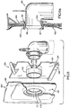
- FIG. 2 is a fragmentary, perspective view, illustrating the vacuum cleaner connector and the dust bag prior to the mounting of the dust bag;
- FIG. 3 is a side elevation, partially in section, illustrating the connector and dust bag in the mounting and removal position;
- FIG. 3a is a fragmentary view, taken along
line 3a - 3a of FIG. 3; - FIG. 4 is a side elevation, partially in section, illustrating the connector and dust bag in the fully mounted and locked position;
- FIG.4a is a fragmentary section, taken along
line 4a - 4a of FIG. 4;
FiG. 1 to 4a correspond to a cleaner known from WO 89 124 93 published on 28.12.1989. - FIG. 5 is an exploded perspective view of a first embodiment of an adaptor for coupling a bag assembly to the vacuum cleaner connector which delivers dirt laden air to the bag assembly;
- FIG. 5a is a fragmentary cross-sectional view of the components of FIG. 5 in assembled relation;
- FIG. 6 is an exploded perspective view of a second embodiment of an adaptor for coupling a bag assembly to the vacuum cleaner connector;
- FIG. 6a is a fragmentary cross-sectional view of the components of FIG. 6 in assembled relation;
- FIG. 7 is an exploded perspective view of still another embodiment of the adaptor for coupling a bag assembly to the vacuum cleaner connector; and
- FIG. 7a is a fragmentary cross-sectional view of the components of FIG. 7 in assembled relation.
- FIG. 1 schematically illustrates a disposable dust bag and mounting system as known applied to a typical
upright vacuum cleaner 10. Thevacuum cleaner 10 includes a motor andfan housing assembly 11. Such cleaners are particularly adapted for carpet and rug cleaning, and in many instances can be provided with various types of attachments for other types of cleaning operations. - Dirt-laden air is discharged by the fan through a
flexible hose 12 which extends upwardly from thehousing assembly 11 within acloth dust bag 13. Thedust bag 13 is connected at 14 to thehousing assembly 11, and is supported at its upper end from thehandle 16 of the vacuum cleaner. Adisposable dust bag 17 incorporating the present invention is installed during use within thecloth dust bag 13. Normally, thecloth dust bag 13 is provided with azipper 18 which can be opened to provide access for the mounting and removal of thedisposable dust bag 17. - Mounted on the upper end of the
flexible hose 12 is aconnector 19 which is connected to thedisposable dust bag 17, as described in greater detail below, and through which dirt-laden air passes into thedisposable dust bag 17. Thedust bag 17 is provided with a mountingcollar 21 which is removably mounted to theconnector 19 so that all of the dirt-laden air from the cleaner enters the dust bag where the dirt is collected. - The overall structure of the
connector 19 and the mounting collar of thedisposable dust bag 17 is best illustrated in FIG. 2. Theconnector 19, in the illustrated embodiment, is a molded plastic part providing a generallycylindrical inlet 22 connected by suitable means to theflexible hose 12. The dirt-laden air enters theconnector 19 through theinlet 22 of theconnector 19 and is discharged through a generallycylindrical outlet portion 23, which in the illustrated embodiment extends at right angles to theinlet 22. - Substantially adjacent to the
end 24 of theoutlet portion 23, the connector is provided with a pair of peripherally spaced mountingprojections connector 19 when thedust bag 17 is mounted thereon. As best illustrated in FIGS. 3a and 4a, therearward walls projections - The mounting
collar 21, in the illustrated embodiment, includes twolayers elastomeric diaphragm 33. The layer ofcardboard 31 is also adhesively secured to thewall 34 of the disposable dust bag around theinlet 35 therein. The dust bag is formed of an air-permeable paper material of the general type used in the past to form disposable dust bags for vacuum cleaners and the like, and is folded and seamed to define an elongated bag structure which defines achamber 35a in which the dirt is collected. - Preferably, the mounting
collar 21 is located at a location spaced from theupper end 36 and thelower end 37 of the dust bag. In use, the dirt-laden air enters the bag from theconnector 19 through theinlet 35, and the material forming the bag allows the air to pass out through thebag 17 and thecloth dust bag 13 to the environment while preventing the passage of the particles of dirt entrained within the air. Such dirt tends to collect in the lower part of the bag and because the inlet is spaced from theupper end 36 of the bag, the upper portion of the bag remains relatively clear of collected dirt so that substantially free passage of the air occurs from the dust bag. In normal use, the dust bag is removed and discarded along with the dirt collected therein when the level of the dirt approaches the level of the inlet at the mounting collar. By providing the inlet at a location below the upper end of the dust bag, the tendency for back pressure to be built up during the use of the cleaner is minimized and the efficiency of the cleaner is maintained until the bag is substantially filled to the level of the inlet provided by thecollar 21. - Referring to FIGS. 2 to 4a, the two
layers collar 21 are formed with identical openings 41 therein and thediaphragm 33 is formed with acircular opening 42 which is substantially smaller than the openings 41 in the twocollar layers - The openings 41 are circular, except for two radially extending,
enlarged portions projections connector 19. - The
projections connector 19 and theenlarged portions enlarged portions projections collar 21 with respect to theconnector 19. In such position, thecollar 21 is initially moved to the position illustrated in FIG. 3a, in which thediaphragm 33 engages theend 24 of theconnector 19, and thecircular portions 40 of the opening 41 in the twolayers outlet portion 23 of the connector. Further, theprojections enlarged portions - During the mounting of the bag on the connector, the mounting
collar 21 is pushed from the full-line position illustrated in FIG. 3a to the phantom-line position, in which the collar extends behind theprojections connector 19 to the fully mounted position illustrated in FIGS. 4 and 4a. In such position, thecircular portions 40 of the collar are positioned behind the twoprojections rearward walls - As best illustrated in FIG. 3a, the
diaphragm opening 42 is substantially smaller than the end of theconnector 19 so that as the mounting collar is pressed over the end of theconnector 19, the diaphragm is stretched to the position illustrated in FIG. 4a, in which the diaphragm extends outwardly along therearward sides 26a and 26b of theadjacent projections projection 26 is spaced back from theend 24 of theconnector 19 and theprojection 27 is substantially adjacent thereto. Consequently, the collar in its mounted position is inclined to some extent with respect to a plane perpendicular to theoutlet portion 36. - As best illustrated in FIG. 4a, the diaphragm is stretched around the exterior wall of the
outlet portion 23 and also extends in along theend 24 of theconnector 19. - Because the
projection 27 is located substantially at theend 24, the diaphragm along that portion of the connector extends inwardly a small distance beyond theend 24 but, adjacent to theprojection 26, the diaphragm engages theend 24 to a lesser extent. In any event, this engagement between the diaphragm and the exterior wall of theconnector 19 and along theend 24 thereof provides a lip seal which ensures that a fluidtight joint is provided between thedisposable dust bag 17 and the connector. This ensures that all of the dirt-laden air passes into the disposable dust bag and that no leakage occurs. By sizing theopening 42 in the diaphragm substantially smaller than theend 24 of the connector, it is ensured that the diaphragm maintains this lip seal and does not blow through and invert during the operation of the cleaner. - Further, the diaphragm provides a very snug mechanical contact with the end of the connector which frictionally maintains the dust bag in its mounted position and during the use of the cleaner.
- When the level of dirt collected in the dust bag reaches substantially to the level of the inlet provided by the mounting ring, the dust bag is rotated in the opposite direction to again bring the
enlarged portions projections - The rotation of the collar and diaphragm with respect to the end connector during the mounting and removal of the disposable dust bag, as mentioned above, is resisted by the frictional engagement between the diaphragm and the end of the
connector 19. However, such friction is not difficult to overcome and the mounting and removal of the dust bag on the connector are easily accomplished by the user. However, such friction is sufficient to reliably prevent rotation of the collar back to the removal position during the use of the cleaner. - Preferably, the face of the collar is provided with printed
indicia 45 to indicate the proper position for the mounting of the dust bag on the collar and for its removal. - With the present invention, a low-cost, reliable structure is provided which can be easily installed and removed by the user, and which ensures that a good seal is provided between the dust bag and the connector.
- The
connector 50 illustrated in FIGS. 5 - 7 has the same general configuration as that shown in the earlier FIGS. 1 - 4 with the major difference being the addition of aperipheral flange 51 and the mountingcollar 21 of thebag 17 is mountable directly on thisconnector 50. The connector has the shape of a tubular el of round cross-section. As in the case of the earlier describedconnector 19, theconnector 50 is a thin walled injection molded plastic body of suitable material such as copolymer polypropylene. The outside diameter of the connector is nominally 2-1/2 inches (1 inch = 2,54 cm) while the inside diameter of the connector is nominally slightly less than 2-3/8 inches (1 inch = 2,54 cm), by way of example, and this size enables the connector andhose 12 to carry an adequate air flow without undue restriction. A lowervertical end 52 of theconnector 50, forming its inlet, is received in theflexible hose 12 in the same manner as the previously describedconnector 19. Theconnector 50 receives dirty air, delivered from the fan of thevacuum cleaner 10 through thehose 12. An upperhorizontal end 53 forms the outlet of theconnector 50. Theoutlet end 53 includes acircular nipple portion 54 from which theflange 51 projects. At its terminus, the exterior of thenipple portion 54 has a peripheral radially extending rib 56 (FIG. 6a) formed through the existence of an immediately adjacentperipheral groove 57. A pair of diametrically opposite projections rise radially above the circular periphery of thenipple portion 54 and lying in a common radial plane. Theprojections 58 are substantially identical, each having a circumferential length substantially less than the circumference of thenipple portion 54. Theprojections 58 have a limited radial extent beyond the adjacent circular areas of thenipple 54 and project radially from this nipple portion to a lesser degree than does theflange 51. Theprojections 58 include walls or surfaces 59 which face rearwardly away from an end face orterminus 60 of thenipple portion 54. - The base of the
flange 51, where it meets the periphery of thecircular nipple portion 54, is spaced axially inward from theprojections 58 at least a distance corresponding to the thickness of a mountingcollar 61 of adisposable bag assembly 62. Theflange 51 is dished so that it is concave on aface 63 adjacent thenipple end 60 and its radiallyouter periphery 64 is closely adjacent the radial plane common to theprojections 58. - The exterior of the connector inward or upstream of the
flange 51 is relatively smooth and circular, being devoid of any significant surface formations or extensions except for avertical bracket 66 from which theconnector 50 is suspended and small circumferentially extending spacedribs 67 that help anchor thehose 12 to theinlet 52. - A
disposable bag assembly 62 shown fragmentarily in FIGS. 5 - 7 is of generally known construction. Thebag assembly 62 comprises foldableporous sheet material 69 such as paper folded or otherwise shaped into an envelope or pouch that is closed except for amouth opening 71. While themouth opening 71 is shown as a die cut circular hole, it may take other forms such as a set of intersecting radial slits as is known in the art. Themouth opening 71 is surrounded by a mounting collar orplate 61 permanently secured to the bag sheet stock by adhesive or other suitable means. The mounting collar has around aperture 72 aligned with the bag sheet opening oraperture 71 so that dirty air can pass into the interior of thebag assembly 62 through these openings. - Preferably, the
bag assembly 62 includes an elastomeric diaphragm seal in the form of a thin web orsheet 73 permanently adhered or otherwise sandwiched between twoplies collar 61. Therubber seal 73 has around hole 76 aligned with the collar and bag sheet apertures with a somewhat smaller diameter than that of thecollar aperture 72. The mountingcollar 61, in the illustrated case, has its plies made of cardboard that are generally planar and together form a relatively rigid structure as compared to thebag sheet stock 69. In the illustrated example, the outer peripheral edges 76 - 79 of the mountingcollar 61 form the general configuration of a rectangle although various other shapes can be used. The mountingcollar 61 has oppositely facingsurfaces inner ply 74 of thecollar 61 is preferably glued or otherwise permanently attached to thebag sheet material 69 in a zone circumferentially continuous about themouth opening 71. Similarly, the collar plies 74, 75 are attached to one another and to theelastomeric seal 73 in such a manner that air leakage paths are eliminated across their mating planes in a known manner. - The
bag assembly 62 of FIGS. 5 - 7 is intended to represent a general form of disposable bag for an upright vacuum cleaner such as that shown in FIG. 1. Thebag assembly 62, in accordance with the invention, can be coupled to theconnector 50 by an adaptor article shown in various forms in FIGS. 5 - 7. Theadaptor 84 illustrated in FIGS. 5 and 5a is a one-piece injection molded part of a suitable thermoplastic material such as polypropylene. Theadaptor 84 is capable of being attached to theconnector 50 and of retaining thebag assembly 62 in coupled relation to the connector. The adaptor of FIG. 5 comprises a generallyflat plate body 86 with acentral aperture 87 arranged to fit over thenipple end portion 54 of theconnector 50. The profile of theopening 87 includesarcs 88 of a common circle interrupted by circumferentially extendingnotches 89 of a radius larger than that of the arcs. The profile of theopening 87 is analogous to the openings 41 in the mountingcollar 21 of the bag illustrated in FIGS. 2 - 4. That is to say, theopening 87 is complementary to the circular shape of theoutlet nipple 54 and associatedprojections 58 of theconnector 50. - The
adaptor 84 is installed ordinarily by the user of a vacuum cleaner, on theconnector 50 by angularly aligning thenotches 89 with theprojections 58, pushing theadaptor plate 86 over thenipple end 60 towards theflange 51 axially past parts of theprojections 58 and finally rotating theadaptor 84 on the outlet nipple so that thenotches 89 andprojections 58 are misaligned. In this installed condition marginal areas of theadaptor plate body 86 around theopening 87 are trapped behind and grip the rearward or reversesurfaces 59 of the projections thereby preventing separation of the adaptor from the connector. The gripping capability of the adaptor on theprojections 58 is sufficient to withstand air pressure forces tending to separate the bag assembly from the connector when thebag assembly 62, as described below, is installed. - At one edge, the
adaptor 84 has achannel 91 proportioned to receive alower edge 79 of the mountingcollar 61. The channel orslot 91 includes asurface 92 that grips thebag mounting collar 61 through its reverse face, i.e. theface 82 facing towards the interior of thebag assembly 62. On a side of theadaptor 84 opposite thechannel 91 there is provided ahook 93 for gripping the margin or edge 76 of thebag collar 61 at itsreverse face 82. Thehook 93 is pivotal about an integral or livinghinge 94 that is provided by a integrally moldedbracket 96. Thehook 93 has acatch surface 97 adapted to grip thereverse collar face 82. - The
bag assembly 62 is coupled to the connector by first positioning the lower mountingcollar edge 79 in theadaptor channel 91. Theupper edge 76 is thereafter pushed against anangled surface 98 of thehook 93 causing the hook to rise by pivoting about thehinge 94. Theupper collar edge 76 slips under the hook and the natural elasticity of thehinge 94 causes the hook to snap over the bag collar permitting thecatch surface 97 to grip thereverse face 82 of the mountingcollar 61. As illustrated in FIG. 5a, theapertures connector nipple portion 54. Theelastomeric seal 73 forms a lip seal over therib 56 preventing axial leakage of air at this point. - With the various elements assembled as illustrated in FIG. 5a, the adaptor is effective to retain the
bag assembly 62 in coupled relation with theconnector 50 with sufficient gripping force on both the connector and the bag assembly to withstand air pressure forces ordinarily encountered in the operation of the vacuum cleaner and thereby prevent unwanted release of the bag assembly from the connector. - FIG. 6 illustrates another form of an
adaptor 184 for coupling abag assembly 162 to theconnector 50. Elements that are essentially structurally and functionally the same as those found in theadaptor 84 of FIG. 5 are designated with identical numerals. Theadaptor 184 which can be a unitary injection molded thermoplastic part has a generally planar plate-like body 101. A lower edge of thebody 101 includes achannel 191 providing a bagcollar gripping surface 192. Approximately at its geometric center, theplate body 101 has acircular tube 102 with an axis extending perpendicularly to the plane of the body. Thetube 102 has an inside diameter dimensioned to fit over thenipple portion 54 of theconnector 50. Adjacent one end, thetube 102 includes a radially inwardly extendingflange 103. Aface 104 of theflange 103 is conical or concave. Theadaptor 184 is installed on theconnector 50 by applying a pushing force to drive theflange face 104 against theprojections 58. The conical orientation of thisface 104 causes theflange 103 to expand locally radially outwardly over the projections and allows theflange 103 to enter the space between theprojections 58 andflange 51. In this position, a reverse face orsurface 106 of theflange 103 grips the rearward faces 59 of theprojections 58 to securely retain theadaptor 184 on theconnector 50. The inner periphery of theflange 103 forms a circumferential airtight seal against the outer periphery of thenipple portion 54. - The
bag assembly 162 is substantially the same as thebag assembly 62 described in connection with FIG. 5 except that a somewhatlarger aperture 172 is provided in thebag mounting collar 161 to enable the collar to slip over the outside of thetube 102. Other parts of thebag assembly 162 which are essentially the same in construction and function as those of theassembly 62 are designated with the same numerals. Thebag assembly 162 is installed in generally the same manner as theassembly 62. It will be seen, however, that theelastomeric seal 73 envelopes and circumferentially seals anend portion 107 of thetube 102 rather than sealing directly on a surface of theconnector 50. Thebag assembly 162, however, is sealed to theconnector 50 by thetube flange 103. - FIG. 7 illustrates still another form of an
adaptor 284. Theadaptor 284 like the earlier examples, can be an integral body formed, for example, as an injection molded thermoplastic part. Theadaptor 284 includes a generally planarmain body plate 111 that has acentral slot 112 extending vertically from alower edge 113 to its midsection. The slot has a width the same as or slightly wider than the outside diameter of theconnector 50. Achannel 291 on thelower edge 113 of theplate 111 is adapted to receive the lower edge of the bagassembly mounting collar 61. - The
adaptor 284 is installed by passing it over theoutlet nipple portion 54 inward (upstream) of theflange 51 and sliding it downwardly so that an end orbight 114 of theslot 112 rests against the outside diameter of the outlet nipple. The edge of theslot 112 at and adjacent thisbight 114 grip theoutlet nipple 54 at the base of theflange 51 to resist bag separation forces. Thebag assembly 62 is coupled to theconnector 50 by theadaptor 284 in essentially the same manner as before described with reference to theadaptor 84. - The various disclosed
adaptors connector 50 indefinitely and bags can be periodically removed from the adaptor and connector when filled to capacity and replaced with a new bag. Other styles of bag adaptors utilizing the principles of the invention are envisioned. The adaptor can be arranged to be removable with the bag or can be arranged to be installed after the bag is positioned on the connector. Additionally, the adaptor can be constructed to work with other bag mounting collars such as a round collar. Further, the adaptor can be structured to grip connector surfaces other than those already described such as the vertical cylindrical wall, adjacent the zone where it intercepts with the horizontal cylindrical wall, or the interior of the outlet nipple.
Claims (20)
- A vacuum cleaner comprisinga connector (50) having an end (53) with a generally cylindrical wall (54) providing an outlet through which dirt-laden air is discharged;a disposable dust bag (62) which is formed of air permeable material (69) and provides a dust collection chamber having an inlet (71) and an elastomeric seal (73) around the inlet providing a generally circular opening; andan adaptor (84);wherein the adaptor (84) and connector (50) are adapted to be coupled together to form an assembly having a sealing surface (56, 57; 107), the adaptor including bag engagement structure (91, 92, 93, 97; 191, 192; 291) for coupling to the bag such that the outlet in the assembly is placed in fluid connection with the inlet and the seal engages the sealing surface in substantially airtight manner, thus to provide a substantially airtight seal between the bag and connector,
characterised in that
the adaptor (84) and connector (50) are separably coupled together by
the connector end comprising at least one projection (51, 58) which extends peripherally outward from the connector end at a location spaced from the outlet,
the projection (51, 58) engaging a first surface of the adaptor which faces in the direction of the outlet, to prevent separation of the adaptor from the connector end by direct movement relative thereto in the direction of the outlet. - A vacuum cleaner according to claim 1 wherein the sealing surface is formed on the connector, and the end (53) of the connector communicates directly with the dust bag.
- A vacuum cleaner according to claim 1 wherein the sealing surface is formed on the adaptor.
- A vacuum cleaner according to claim 3 wherein the adaptor comprises a tubular member (102) which communicates directly with the dust bag, and the end (53) of the connector communicates with the tubular member (102).
- A vacuum cleaner according to claim 4 wherein the sealing surface is provided on the tubular member.
- A vacuum cleaner according to any preceding claim wherein the adaptor includes an aperture (87) or slot (112) for accommodating the connector end.
- A vacuum cleaner according to claim 6 as dependent on claim 4 or claim 5 wherein the aperture is formed in the tubular member.
- A vacuum cleaner according to claim 6 wherein the aperture or slot is formed in a planar sheet member (111) of the adaptor.
- A vacuum cleaner according to any preceding claim wherein the radial extent of the projection(s) is substantially less than the radius of the cylindrical wall.
- A vacuum cleaner according to any preceding claim wherein the projection(s) extend in a substantially radial plane.
- A vacuum cleaner according to any preceding claim wherein there are at least two said projections.
- A vacuum cleaner according to claim 6 and claim 11 wherein the aperture is shaped to receive the projections as in a bayonet fitting, whereby mutual rotation of adaptor and connector is necessary to assemble or separate the assembly.
- A vacuum cleaner according to claim 11 or claim 12 wherein the two projections are coplanar.
- A vacuum cleaner according to any preceding claim wherein the connector end comprises a radially extending flange (51) axially spaced from the outlet.
- A vacuum cleaner according to claim 6 and claim 14 wherein the aperture is radially smaller than the flange such that in the assembly a surface of the flange abutably engages a second surface (64) on the adaptor opposed to the first surface.
- A vacuum cleaner according to any one of claims 1 to 3 wherein the adaptor includes a longitudinal slot (112) for accommodating the connector end, and the projection comprises a radially extending flange (51) wider than the slot for engaging the first surface of the adaptor in the assembly.
- A vacuum cleaner according to claim 16 wherein the connector end extends at an angle relative to the rest of the connector, and in the assembly a surface of the adaptor opposed to the first surface abuts the a part of the rest of the connector.
- A vacuum cleaner according to any one of claims 14 to 17 wherein the flange comprises a continuous flange.
- A vacuum cleaner according to any preceding claim, being an upright vacuum cleaner (10) having an outer permanent filter bag (13), the connector comprising an L-shaped structure (19) of circular tube including the end.
- A vacuum cleaner according to any preceding claim wherein
the bag has a relatively rigid collar (61) attached around the opening, and
the bag engagement structure of the adaptor comprises collar engagement means (91, 92, 93, 97) for holding the collar in fixed relation to the assembly such that the seal engages the sealing surface.
Applications Claiming Priority (3)
| Application Number | Priority Date | Filing Date | Title |
|---|---|---|---|
| US37826489A | 1989-07-11 | 1989-07-11 | |
| US378264 | 1989-07-11 | ||
| PCT/US1990/003826 WO1991000707A1 (en) | 1989-07-11 | 1990-07-06 | Disposable dust bag for vacuum cleaners and the like |
Publications (3)
| Publication Number | Publication Date |
|---|---|
| EP0433439A1 EP0433439A1 (en) | 1991-06-26 |
| EP0433439A4 EP0433439A4 (en) | 1991-11-21 |
| EP0433439B1 true EP0433439B1 (en) | 1997-01-29 |
Family
ID=23492405
Family Applications (1)
| Application Number | Title | Priority Date | Filing Date |
|---|---|---|---|
| EP90911721A Expired - Lifetime EP0433439B1 (en) | 1989-07-11 | 1990-07-06 | Vacuum cleaner with a particular mounting structure for disposable dust bags |
Country Status (9)
| Country | Link |
|---|---|
| EP (1) | EP0433439B1 (en) |
| AU (1) | AU633948B2 (en) |
| CA (1) | CA2035890C (en) |
| DE (1) | DE69029843T2 (en) |
| DK (1) | DK0433439T3 (en) |
| NO (1) | NO179123C (en) |
| SG (1) | SG65574A1 (en) |
| WO (1) | WO1991000707A1 (en) |
| ZA (1) | ZA905400B (en) |
Families Citing this family (7)
| Publication number | Priority date | Publication date | Assignee | Title |
|---|---|---|---|---|
| DE69521195T2 (en) * | 1995-03-08 | 2001-11-15 | Whirlpool Europ | Connectors for refrigerators, freezers and the like |
| DE102008041227A1 (en) * | 2008-08-13 | 2010-02-18 | BSH Bosch und Siemens Hausgeräte GmbH | Dust bags |
| WO2012166929A1 (en) * | 2011-05-31 | 2012-12-06 | Zenith Technologies, L.L.C. | Vacuum bag attachment assembly |
| DE202015000249U1 (en) * | 2015-01-19 | 2016-01-20 | Michaela Walther | filter element |
| DK3326507T3 (en) * | 2016-11-23 | 2022-07-25 | Electrolux Ab | DEVICES FOR DUST CONTAINERS FOR VACUUM CLEANERS |
| CN107855514A (en) * | 2017-12-11 | 2018-03-30 | 机械工业第六设计研究院有限公司 | Process layout's structure in environment-friendly type casting pouring area |
| DE102021121083A1 (en) * | 2021-08-13 | 2023-02-16 | Miele & Cie. Kg | anthers |
Family Cites Families (11)
| Publication number | Priority date | Publication date | Assignee | Title |
|---|---|---|---|---|
| NL120373C (en) * | 1962-05-05 | |||
| US3242654A (en) * | 1963-03-26 | 1966-03-29 | Kingston Products Corp | Disposable bag assembly for vacuum cleaner |
| US3417550A (en) * | 1965-10-04 | 1968-12-24 | Studley Paper Company Inc | Disposable vacuum cleaner filter bag |
| US3675399A (en) * | 1969-04-21 | 1972-07-11 | Whirlpool Co | Vacuum cleaner |
| SE421857B (en) * | 1978-09-25 | 1982-02-08 | Electrolux Ab | DEVICE AT A DUST SUCCESS STAGE |
| US4262384A (en) * | 1980-01-25 | 1981-04-21 | The Scott & Fetzer Company | Vacuum cleaner bag assembly |
| US4364757A (en) * | 1981-08-24 | 1982-12-21 | The Hoover Company | Vacuum cleaner filter bag collar arrangement |
| US4514199A (en) * | 1984-05-25 | 1985-04-30 | The Scott & Fetzer Company | Vacuum cleaner dirt box |
| US4591369A (en) * | 1984-10-24 | 1986-05-27 | Whirlpool Corporation | Dust bag mount arrangement for canister vacuum cleaner |
| US4738697A (en) * | 1986-12-09 | 1988-04-19 | Whirlpool Corporation | Vacuum cleaner bag mount and method for mounting a dust bag thereon |
| US4877432A (en) * | 1988-06-17 | 1989-10-31 | The Scott Fetzer Company | Disposable dust bag for vacuum cleaners and the like |
-
1990
- 1990-07-06 AU AU60580/90A patent/AU633948B2/en not_active Ceased
- 1990-07-06 SG SG1996005806A patent/SG65574A1/en unknown
- 1990-07-06 DE DE69029843T patent/DE69029843T2/en not_active Expired - Lifetime
- 1990-07-06 DK DK90911721.0T patent/DK0433439T3/en active
- 1990-07-06 CA CA002035890A patent/CA2035890C/en not_active Expired - Fee Related
- 1990-07-06 EP EP90911721A patent/EP0433439B1/en not_active Expired - Lifetime
- 1990-07-06 WO PCT/US1990/003826 patent/WO1991000707A1/en active IP Right Grant
- 1990-07-10 ZA ZA905400A patent/ZA905400B/en unknown
-
1991
- 1991-03-05 NO NO910854A patent/NO179123C/en unknown
Also Published As
| Publication number | Publication date |
|---|---|
| EP0433439A4 (en) | 1991-11-21 |
| DE69029843T2 (en) | 1997-06-19 |
| DE69029843D1 (en) | 1997-03-13 |
| DK0433439T3 (en) | 1997-07-14 |
| EP0433439A1 (en) | 1991-06-26 |
| SG65574A1 (en) | 1999-06-22 |
| NO179123C (en) | 1996-08-14 |
| CA2035890A1 (en) | 1991-01-12 |
| NO179123B (en) | 1996-05-06 |
| CA2035890C (en) | 1999-09-14 |
| NO910854L (en) | 1991-05-10 |
| AU633948B2 (en) | 1993-02-11 |
| ZA905400B (en) | 1992-03-25 |
| AU6058090A (en) | 1991-02-06 |
| NO910854D0 (en) | 1991-03-05 |
| WO1991000707A1 (en) | 1991-01-24 |
Similar Documents
| Publication | Publication Date | Title |
|---|---|---|
| US5092915A (en) | Disposable dust bag for vacuum cleaners and the like | |
| US5064455A (en) | Disposable dust bag for vacuum cleaners and the like | |
| US4877432A (en) | Disposable dust bag for vacuum cleaners and the like | |
| US5464460A (en) | Disposable dust bag for vacuum cleaner and the like | |
| US5089038A (en) | Bag mount assembly for a vacuum cleaner | |
| CA1164610A (en) | Vacuum cleaner bag assembly | |
| JP3507034B2 (en) | Suction vacuum cleaner bag docking assembly | |
| US4364757A (en) | Vacuum cleaner filter bag collar arrangement | |
| US4748713A (en) | Vacuum cleaner assembly | |
| CA2859020C (en) | Vacuum filter bag mounting apparatus and methods of operation | |
| US7779507B2 (en) | Vacuum cleaner | |
| CA2782532A1 (en) | Vacuum bag and vacuum bag attachment assembly | |
| EP0433439B1 (en) | Vacuum cleaner with a particular mounting structure for disposable dust bags | |
| CN102238892B (en) | Vacuum cleaner bag docking assembly | |
| US6886215B2 (en) | Vacuum cleaner fill tube with valve | |
| WO1992013479A1 (en) | Fastening device for a dust bag in a vacuum cleaner | |
| CA2551200C (en) | Vacuum cleaner having hose detachable at nozzle | |
| WO2004049888A1 (en) | Vacuum cleaner | |
| JPH0354684Y2 (en) | ||
| CA2502457C (en) | Vacuum cleaner bag docking assembly |
Legal Events
| Date | Code | Title | Description |
|---|---|---|---|
| PUAI | Public reference made under article 153(3) epc to a published international application that has entered the european phase |
Free format text: ORIGINAL CODE: 0009012 |
|
| AK | Designated contracting states |
Kind code of ref document: A1 Designated state(s): DE DK GB IT |
|
| 17P | Request for examination filed |
Effective date: 19910715 |
|
| A4 | Supplementary search report drawn up and despatched |
Effective date: 19910930 |
|
| AK | Designated contracting states |
Kind code of ref document: A4 Designated state(s): DE DK GB IT |
|
| 17Q | First examination report despatched |
Effective date: 19930528 |
|
| GRAG | Despatch of communication of intention to grant |
Free format text: ORIGINAL CODE: EPIDOS AGRA |
|
| GRAH | Despatch of communication of intention to grant a patent |
Free format text: ORIGINAL CODE: EPIDOS IGRA |
|
| GRAH | Despatch of communication of intention to grant a patent |
Free format text: ORIGINAL CODE: EPIDOS IGRA |
|
| GRAA | (expected) grant |
Free format text: ORIGINAL CODE: 0009210 |
|
| AK | Designated contracting states |
Kind code of ref document: B1 Designated state(s): DE DK GB IT |
|
| REF | Corresponds to: |
Ref document number: 69029843 Country of ref document: DE Date of ref document: 19970313 |
|
| ITF | It: translation for a ep patent filed |
Owner name: 0508;38MIFSTUDIO ING. ALFREDO RAIMONDI |
|
| REG | Reference to a national code |
Ref country code: DK Ref legal event code: T3 |
|
| PLBE | No opposition filed within time limit |
Free format text: ORIGINAL CODE: 0009261 |
|
| STAA | Information on the status of an ep patent application or granted ep patent |
Free format text: STATUS: NO OPPOSITION FILED WITHIN TIME LIMIT |
|
| 26N | No opposition filed | ||
| REG | Reference to a national code |
Ref country code: GB Ref legal event code: IF02 |
|
| PGFP | Annual fee paid to national office [announced via postgrant information from national office to epo] |
Ref country code: DK Payment date: 20090714 Year of fee payment: 20 |
|
| PGFP | Annual fee paid to national office [announced via postgrant information from national office to epo] |
Ref country code: GB Payment date: 20090701 Year of fee payment: 20 Ref country code: DE Payment date: 20090702 Year of fee payment: 20 |
|
| PGFP | Annual fee paid to national office [announced via postgrant information from national office to epo] |
Ref country code: IT Payment date: 20090720 Year of fee payment: 20 |
|
| REG | Reference to a national code |
Ref country code: DK Ref legal event code: EUP |
|
| REG | Reference to a national code |
Ref country code: GB Ref legal event code: PE20 Expiry date: 20100705 |
|
| PG25 | Lapsed in a contracting state [announced via postgrant information from national office to epo] |
Ref country code: GB Free format text: LAPSE BECAUSE OF EXPIRATION OF PROTECTION Effective date: 20100705 |
|
| PG25 | Lapsed in a contracting state [announced via postgrant information from national office to epo] |
Ref country code: DE Free format text: LAPSE BECAUSE OF EXPIRATION OF PROTECTION Effective date: 20100706 |