EP0433216A1 - Weft distributing device for a multiphase linear shed loom with air picking - Google Patents
Weft distributing device for a multiphase linear shed loom with air picking Download PDFInfo
- Publication number
- EP0433216A1 EP0433216A1 EP90810754A EP90810754A EP0433216A1 EP 0433216 A1 EP0433216 A1 EP 0433216A1 EP 90810754 A EP90810754 A EP 90810754A EP 90810754 A EP90810754 A EP 90810754A EP 0433216 A1 EP0433216 A1 EP 0433216A1
- Authority
- EP
- European Patent Office
- Prior art keywords
- weft
- distributing device
- channel
- channels
- separating
- Prior art date
- Legal status (The legal status is an assumption and is not a legal conclusion. Google has not performed a legal analysis and makes no representation as to the accuracy of the status listed.)
- Granted
Links
- 238000009941 weaving Methods 0.000 claims abstract description 27
- 238000007789 sealing Methods 0.000 claims abstract description 25
- 230000001154 acute effect Effects 0.000 claims description 3
- 238000007664 blowing Methods 0.000 claims description 3
- 238000003780 insertion Methods 0.000 claims description 3
- 230000037431 insertion Effects 0.000 claims description 3
- 239000000463 material Substances 0.000 claims description 3
- 239000000314 lubricant Substances 0.000 claims description 2
- 238000009423 ventilation Methods 0.000 claims description 2
- 238000010304 firing Methods 0.000 claims 1
- 230000000694 effects Effects 0.000 abstract description 5
- 210000001520 comb Anatomy 0.000 description 3
- 239000004744 fabric Substances 0.000 description 3
- 230000015572 biosynthetic process Effects 0.000 description 2
- 230000007704 transition Effects 0.000 description 2
- 230000001133 acceleration Effects 0.000 description 1
- 230000005540 biological transmission Effects 0.000 description 1
- 238000007598 dipping method Methods 0.000 description 1
- 238000002347 injection Methods 0.000 description 1
- 239000007924 injection Substances 0.000 description 1
- 230000002093 peripheral effect Effects 0.000 description 1
Images

Classifications
-
- D—TEXTILES; PAPER
- D03—WEAVING
- D03D—WOVEN FABRICS; METHODS OF WEAVING; LOOMS
- D03D41/00—Looms not otherwise provided for, e.g. for weaving chenille yarn; Details peculiar to these looms
- D03D41/005—Linear-shed multiphase looms
Definitions
- the invention relates to a weft distributing device of a row shed loom with air intake. Such a device is described in EP-PS 0 143 860.
- the interfaces for the weft thread are located relatively far from the fabric wheel and discontinuous movements of transmission elements are necessary for the distribution of the weft threads.
- Another advantageous embodiment is the subject of the present invention. It solves the task of distributing and blowing into the different weft channels of a weaving rotor with low acceleration forces in the weft thread.
- the object is achieved in that the device has a stationary part and a part rotating with the weaving rotor, which have a common rotationally symmetrical separating and sealing surface, via which the transfer of weft threads takes place, and by a shooting tube on the rotating part of each weft channel Part is assigned, in which a feed nozzle, which is positioned in the stationary part, blows the weft by means of air.
- a weft distributing device of a row shed loom with air intake is shown.
- the warp threads 9 from the warp beam 1 are guided tangentially to a rotating weaving rotor 4 via deflections 3 and deflected within a certain deflection area by combs 6, which are arranged in rows to form weft channels 7, for shed formation.
- weft threads 10 are inserted, which are taken along with the combs dipping through the warp threads until the newly formed cloth runs tangentially.
- the cloth is wound on the merchandise tree 2.
- the weft threads 10 are distributed by a thread feed device 31 to a plurality of weft channels 7 of a weaving rotor 4 in that the device has a stationary part 21 and a part 11 which also rotates with the weaving rotor 4 and which have a common separating and sealing surface 20 in a rotationally symmetrical surface.
- each weft channel 7 is assigned a shooting tube 12 on the rotating part 11, into which a feed nozzle 22, which is positioned in the stationary part 21, blows the weft thread 10 by means of air.
- the orifices 15 of the shooting tubes 12 lie on a shooting circle 8 and are evenly distributed there for each feed nozzle 22 and offset from one feed nozzle to the next at a weft channel distance.
- the transition of the weft thread from the stationary to the rotating part takes place from a connecting channel 24 in the stationary part 21, which describes a circular arc piece in the direction of rotation and is open to the separating and sealing surface 20, to a take-over channel 14, which in the rotating part 11 with the stripping shoulder 13 of the shooting tube 12 begins, which continues in the direction of rotation as a circular arc piece with the same diameter as the connecting channel and which is open to the separating and sealing surface, so that over time from the departure of an opening edge 16 on a fixed edge 27 until the arrival of the Ab Scraper shoulder 13 on the edge 27 no blind spaces must be passed when entering a newly formed weft tip.
- the scraper shoulder 13 goes away from the separating and sealing surface 20 at approximately a right angle. From Fig. 3 it follows that the preceding stripping shoulder 13a and its associated shooting tube 12 are open for a certain time at the same time as the following shooting tube 12 to the connecting channel 24 so that the new weft thread tip created in the clamping and cutting device 32 is pulled back and can be entered via the following shooting tube 12.
- the coaxially arranged feed nozzle 22 and auxiliary nozzle 26 blow against the direction of rotation at an acute angle to the center line of the connecting channel 24 and act as an injector to counteract this seen in the direction of rotation, on the one hand generates an overpressure in the area behind the nozzle opening via a mixing section and on the other hand generates a negative pressure in relation to the atmosphere in the area in front of the nozzle opening.
- an auxiliary nozzle with a square outlet cross section which coaxially includes a feed nozzle with a circular cross section, has proven to be advantageous.
- the thread feed device 31 delivers the weft thread 10 to the weft circle at a higher speed than the peripheral speed, a thread loop is created in the connecting channel to the new shooting tube 12, as long as the weft thread is clamped and cut at the outlet of the associated shooting tube 12. After the new weft thread tip has been cut and released, the loop continues into an elongated weft thread within the weft distribution device.
- 7 relay nozzles 33 are attached along the weft channels, which support the weft insertion from the shooting tubes 12. Clamping and cutting devices 32 are positioned between the bullet tube 12 and the weft channel 7 formed from combs 6.
- the cutting can be carried out with a stationary tool into which the weft threads 10 inevitably run with the rotational movement of the mouth 15 and the weft channel 7.
- the inserted weft thread 10 must be in predetermined circumferential positions with respect to the stationary part 21, e.g. to the feed and auxiliary nozzles 22, 26, clamped, cut and released as a new weft tip.
- the size and the time course of the pulse of the air flow from the feed nozzle 22 and / or auxiliary nozzle 26 are also controlled as a function of the circulating position of the associated weft thread 10.
- the air flow in the guide channels 24, 14, 12 and the air flow of the relay nozzles create a tensile stress in the weft thread, which causes it to bear against the inner diameters of the circular arc pieces from the connecting channel 24 and from the take-over channel.
- the weft thread 10 shifts more to the channel base and away from the separating and sealing surface 20.
- the weft distributing devices shown here can be used to shoot weft threads 10 into a weaving rotor 4 from both sides, with correspondingly more weft channels 7 forming compartments, both systems having to be offset by a weft channel division and the relay nozzles of both systems being oriented in opposite directions have to.
Landscapes
- Engineering & Computer Science (AREA)
- Textile Engineering (AREA)
- Looms (AREA)
Abstract
Description
Die Erfindung betrifft eine Schussfadenverteilvorrichtung einer Reihenfachwebmaschine mit Lufteintrag. Eine derartige Vorrichtung ist in der EP-PS 0 143 860 beschrieben. Die Schnittstellen für den Schussfaden liegen dort relativ weit vom Geweberad entfernt und es sind diskontinuierliche Bewegungen von Uebertragungselementen für die Verteilung der Schussfäden notwendig. Eine weitere, vorteilhafte Ausführung ist Gegenstand der vorliegenden Erfindung. Sie löst die Aufgabe, mit geringen Beschleunigungskräften im Schussfaden die Verteilung auf und das Einblasen in die verschiedenen Schusskanäle eines Webrotors vorzunehmen. Gemäss der Erfindung wird die Aufgabe gelöst, indem die Vorrichtung einen ortsfesten Teil und einen mit dem Webrotor mitrotierenden Teil aufweist, die eine gemeinsame rotationssymmetrische Trenn-und Dichtfläche besitzen, über die die Übergabe von Schussfäden stattfindet, und indem jedem Schusskanal ein Einschiessrohr auf dem mitrotiernden Teil zugeordnet ist, in welches eine Speisedüse, die im ortsfesten Teil positioniert ist, den Schussfaden mittels Luft einbläst.The invention relates to a weft distributing device of a row shed loom with air intake. Such a device is described in EP-PS 0 143 860. The interfaces for the weft thread are located relatively far from the fabric wheel and discontinuous movements of transmission elements are necessary for the distribution of the weft threads. Another advantageous embodiment is the subject of the present invention. It solves the task of distributing and blowing into the different weft channels of a weaving rotor with low acceleration forces in the weft thread. According to the invention, the object is achieved in that the device has a stationary part and a part rotating with the weaving rotor, which have a common rotationally symmetrical separating and sealing surface, via which the transfer of weft threads takes place, and by a shooting tube on the rotating part of each weft channel Part is assigned, in which a feed nozzle, which is positioned in the stationary part, blows the weft by means of air.
Die Vorteile der Erfindung sind darin zu sehen, dass die Verteilung und das Umsteuern der Schussfäden zwangsläufig über geschlossene Kanäle erfolgen, deren Bildung durch die Rotation des Webrotors stattfindet.The advantages of the invention can be seen in the fact that the weft threads are inevitably distributed and reversed via closed channels, the formation of which takes place through the rotation of the weaving rotor.
Im folgenden wird die Erfindung anhand von einem Ausführungsbeispiel beschrieben. Es zeigt:
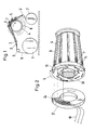
- Fig. 1 die schematische Anordnung de Kettfadenlaufs in einer Reihenfachwebmaschine mit Webrotor;
- Fig. 2 schematisch den Schussfadenübergang vom ortsfesten Teil zum mitrotierenden Teil einer Schussfadenverteilvorrichtung, wobei der ortsfeste Teil seitlich weggeklappt ist;
- Fig. 3 einen schematischen Ausschnitt aus einer Schussfadenverteilvorrichtung, die quer zur Trenn- und Dichtfläche zwischen ortsfestem Teil und mit rotierendem Teil entlang des Fadenverlaufs aufgeschnitten ist;
- Fig. 4 einen radialen Ausschnitt aus der schematischen Darstellung eines Webrotors und einer Schussfadenverteilvorrichtung mit einem ortsfesten und einem mitrotierenden Teil;
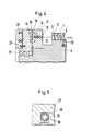
- Fig. 5 einen Schnitt durch eine Hilfsdüse mit koaxial angeordneter Speisedüse im ortsfesten Teil einer Schussfadenverteilvorrichtung.
- 1 shows the schematic arrangement of the warp thread run in a row shed weaving machine with a weaving rotor;
- 2 schematically shows the weft thread transition from the stationary part to the rotating part of a weft thread distribution device, the stationary part being folded away to the side;
- 3 shows a schematic section of a weft distributing device, which is cut across the separating and sealing surface between the stationary part and with the rotating part along the course of the thread;
- 4 shows a radial section from the schematic illustration of a weaving rotor and a weft distributing device with a stationary and a co-rotating part;
- 5 shows a section through an auxiliary nozzle with a coaxially arranged feed nozzle in the stationary part of a weft thread distribution device.
In den Figuren ist eine Schussfadenverteilvorrichtung einer Reihenfachwebmaschine mit Lufteintrag gezeigt. Die Kettfäden 9 vom Kettbaum 1 werden über Umlenkungen 3 tangential an einen drehenden Webrotor 4 geführt und innerhalb eines bestimmten Umlenkbereiches von Kämmen 6, die reihenweise zu Schusskanälen 7 angeordnet sind, zur Fachbildung ausgelenkt. Während der Drehung der so gebildeten Fächer in Drehrichtung 5 werden Schussfäden 10 eingetragen, die mit den durch die Kettfäden tauchenden Kämmen bis zum tangentialen Ablauf des neu gebildeten Tuchs mitgenommen werden. Das Tuch wird auf dem Warenbaum 2 aufgewickelt.In the figures, a weft distributing device of a row shed loom with air intake is shown. The
Erfindungsgemäss werden die Schussfäden 10 von einer Fadenzuführeinrichtung 31 auf mehrere Schusskanäle 7 eines Webrotors 4 verteilt, indem die Vorrichtung einen ortsfesten Teil 21 und einen mit dem Webrotor 4 mitrotierenden Teil 11 aufweist, die in einer rotationssymmetrischen Fläche eine gemeinsame Trenn- und Dichtfläche 20 besitzen, über die die Uebergabe von Schussfäden 10 stattfindet und indem jedem Schusskanal 7 ein Einschiessrohr 12 auf dem mitrotierenden Teil 11 zugeordnet ist, in welches eine Speisedüse 22, die im ortsfesten Teil 21 positioniert ist, den Schussfaden 10 mittels Luft einbläst.According to the invention, the
Jede Speisedüse 22 zieht von einer ihr zugeordneten Fadenzuführeinrichtung 31 einen kontinuierlich zugelieferten Schussfaden 10 ab, dessen Geschwindigkeit in einem festen Verhältnis zur Drehzahl des Webrotors 4 einstellbar ist. Von jeder Speisedüse 22 werden die Schussfäden zyklisch in eine bestimmte Anzahl von m = 4 ihr zugeordneten Einschiessrohre 12 eingeblasen, deren Mündungen 15 in der Achse des jeweiligen Schusskanals 7 liegen, das heisst, das Produkt der Anzahl n = 3 mit Fadenzuführeinrichtungen zugeführten Schussfäden 10 und der Anzahl m = 4 von einem der Schussfäden 10 belieferten Einschiessrohre 12 entspricht der Anzahl von 12 Schusskanälen 7 am Webrotor 4.Each
Entsprechend den Schusskanälen 7 am Webrotor 4 liegen die Mündungen 15 der Einschiessrohre 12 auf einem Einschiesskreis 8 und sind dort für jede Speisedüse 22 gleichmässig verteilt und von einer Speisedüse zur nächsten in einem Schusskanalabstand versetzt.Corresponding to the
Der Uebergang des Schussfadens vom ortsfesten zum mitrotierenden Teil erfolgt von einem Verbindungskanal 24 im ortsfesten Teil 21, der in Drehrichtung ein Kreisbogenstück beschreibt und zur Trenn- und Dichtfläche 20 hin offen ist, zu einem Uebernahmekanal 14, der im mitrotierenden Teil 11 mit der Abstreifschulter 13 des Einschiessrohres 12 beginnt, der sich in Drehrichtung als Kreisbogenstück mit dem gleichen Durchmesser wie der Verbindungskanal fortsetzt und der zur Trenn- und Dichtfläche hin offen ist, damit über die Zeit vom Wegfahren einer öffnenden Kante 16 an einer ortsfesten Kante 27 bis zur Ankunft der Abstreifschulter 13 an der Kante 27 keine Blindräume beim Eintragen einer neu gebildeten Schussfadenspitze passiert werden müssen. Die m = 4 Uebernahmekanäle 14 sind gleichmässig auf dem mit dem Verbindungskanal 24 gemeinsamen Kreis in der Trenn- und Dichtfläche 20 verteilt. Die Abstreifschulter 13 geht annähernd im rechten Winkel von Trenn- und Dichtfläche 20 weg. Aus Fig. 3 ergibt sich, dass die vorangehende Abstreifschulter 13a und ihr zugehöriges Einschiessrohr 12 über eine gewisse Zeit gleichzeitig mit dem nachfolgenden Einschiessrohr 12 zum Verbindungskanal 24 hin offen sind, damit die in der Klemm- und Schneidvorrichtung 32 durch Schnitt entstandene neue Schussfadenspitze zurückgezogen und über das nachfolgende Einschiessrohr 12 eingetragen werden kann.The transition of the weft thread from the stationary to the rotating part takes place from a connecting
Um für das Zurückziehen der neu gebildeten Schussfadenspitze eine Rückströmung und für das Einblasen mit dem nachfolgenden Einschiessrohr eine Düsenwirkung zu erzielen, blasen die koaxial angeordnete Speisedüse 22 und Hilfsdüse 26 entgegen der Drehrichtung in spitzem Winkel zur Mittellinie des Verbindungskanals 24 und wirken als Injektor, der entgegen der Drehrichtung gesehen, einerseits über eine Mischstrecke einen Ueberdruck im Bereich hinter der Düseneinmündung erzeugt und andererseits im Bereich vor der Düsenmündung einen Unterdruck gegenüber der Atmosphäre erzeugt. Um diesen Effekt bei geringem Platzbedarf zu erreichen, hat sich eine Hilfsdüse mit quadratischem Austrittsquerschnitt, die koaxial eine Speisedüse mit Kreisquerschnitt einschliesst, als vorteilhaft erwiesen. Wenn die Fadenzuführeinrichtung 31 den Schussfaden 10 mit einer grösseren Geschwindigkeit als der Umfangsgeschwindigkeit am Einschusskreis anliefert, entsteht eine Fadenschlaufe im Verbindungskanal zum neuen Einschiessrohr 12 hin, solange der Schussfaden am Austritt des davorliegenden zugehörigen Einschiessrohres 12 geklemmt und geschnitten wird. Nach dem Schneiden und Freigeben der neuen Schussfadenspitze geht die Schlaufe noch innerhalb der Schussverteilvorrichtung in einen gestreckten Schussfaden über. Am Webrotor 4 sind längs der Schusskanäle 7 Stafettendüsen 33 angebracht, die den Schusseintrag aus den Einschiessrohren 12 unterstützen. Klemm- und Schneidvorrichtungen 32 sind zwischen Einschussrohr 12 und dem aus Kämmen 6 gebildeten Schusskanal 7 positioniert. Das Schneiden kann mit einem ortsfesten Werkzeug vorgenommen werden, in welches die Schussfäden 10 zwangsläufig mit der Drehbewegung von Mündung 15 und Schusskanal 7 hineinlaufen. Um den Injektoreffekt bei der richtigen Stellung der Führungskanäle 12, 24, 14 auszunutzen, muss der eingetragene Schussfaden 10 in vorgegebenen Umlaufpositionen zum ortsfesten Teil 21, z.B. zu den Speise- und Hilfsdüsen 22, 26, geklemmt, geschnitten und als neue Schussfadenspitze freigegeben werden. Ebenso wird die Grösse und der zeitliche Verlauf des Impulses der Luftströmung aus Speisedüse 22 und/oder Hilfsdüse 26 in Abhängigkeit von der Umlaufposition des zugehörigen Schussfadens 10 gesteuert. Während des Eintragens des Schussfadens in den Schusskanal 7 erzeugt die Luftströmung in den Führungskanälen 24, 14, 12 und die Luftströmung der Stafettendüsen eine Zugspannung im Schussfaden, die ihn an den Innendurchmessern der Kreisbogenstücke vom Verbindungskanal 24 und vom Uebernahmekanal anliegen lässt. Durch Hinterschneiden dieser inneren Flächen verlagert sich der Schussfaden 10 mehr zum Kanalgrund und von der Trenn-und Dichtfläche 20 weg.In order to achieve a backflow for retraction of the newly formed weft thread tip and a nozzle effect for blowing in with the following shooting tube, the coaxially arranged
Als weitere Unterstützung beim Umsteuern der Luftströmung vom vorangehenden zum zugehörigen nachfolgenden Einschiessrohr 12 hat es sich als vorteilhaft erwiesen, mindestens eine Abblaseöffnung 17 im mitrotierenden Teil 11 oder in der ortsfesten Begrenzungsfläche des Uebernahmekanals 14 anzubringen. Je abrupter die Abzweigung und je kleiner die Weite dieser Oeffnungen in Fadenlaufrichtung ist, desto geringen ist die Gefahr für ein Hängenbleiben des Schussfadens. Da die Wirkung der Abblaseöffnungen vor allem während des Umsteuerns der Luftströmung gefordert ist, wird ihr ein Sammelraum mit einstellbarem Ausflusswiderstand nachgeschaltet, wobei der Ausfluss über bestimmte Drehwinkel des Einschussrohres 12 zum ortsfesten Teil 21 vollständig geschlossen werden kann.As a further aid in reversing the air flow from the preceding to the associated following
Um zu grosse Luftverluste und ein Klemmen des Schussfadens 10 in der Trenn- und Dichtfläche 20 zu vermeiden, sind verschieden Massnahmen möglich. Zunächst kann man den Abstand der ortsfesten Fläche zur mitrotierenden Fläche auf weniger als 0,2 mm begrenzen oder die Flächen als Gleitflächen mit einer einstellbaren Anpresskraft aufeinander laufen lassen, was eine verschleissfeste Materialpaarung mit guten Trockenlaufeigenschaften voraussetzt und durch Zugabe eines Schmiermittels unterstützt werden kann. Eine weitere Massnahme besteht im Anbringen von Dichtleisten oder von Sperrluft- oder Entlüftungskanälen, die an der Dichtfläche 20 wirken, indem sie Uebernahme- und Verbindungskanäle umgeben.In order to avoid excessive air losses and jamming of the
Die hier gezeigten Schussfadenverteilvorrichtungen können dazu benutzt werden, von beiden Seiten Schussfäden 10 in einen Webrotor 4 einzuschiessen, wobei entsprechend mehr Schusskanäle 7, die Fächer bilden, vorhanden sein müssen und beide Systeme um eine Schusskanalteilung versetzt sein müssen und die Stafettendüsen beider Systeme gegenläufig orientiert sein müssen.The weft distributing devices shown here can be used to shoot
Claims (32)
Applications Claiming Priority (2)
| Application Number | Priority Date | Filing Date | Title |
|---|---|---|---|
| CH4130/89 | 1989-11-16 | ||
| CH413089 | 1989-11-16 |
Publications (2)
| Publication Number | Publication Date |
|---|---|
| EP0433216A1 true EP0433216A1 (en) | 1991-06-19 |
| EP0433216B1 EP0433216B1 (en) | 1994-04-27 |
Family
ID=4270391
Family Applications (1)
| Application Number | Title | Priority Date | Filing Date |
|---|---|---|---|
| EP90810754A Expired - Lifetime EP0433216B1 (en) | 1989-11-16 | 1990-10-03 | Weft distributing device for a multiphase linear shed loom with air picking |
Country Status (5)
| Country | Link |
|---|---|
| US (1) | US5146955A (en) |
| EP (1) | EP0433216B1 (en) |
| JP (1) | JP2848684B2 (en) |
| DE (1) | DE59005525D1 (en) |
| RU (1) | RU1834930C (en) |
Cited By (15)
| Publication number | Priority date | Publication date | Assignee | Title |
|---|---|---|---|---|
| EP0624673A1 (en) * | 1993-05-13 | 1994-11-17 | Sulzer RàTi Ag | Weft distributing device for a multiphase linear shed loom and multiphase linear shed loom with weft distributing device |
| EP0624672A1 (en) * | 1993-05-13 | 1994-11-17 | Sulzer RàTi Ag | Weft distributing device for a multiphase linear shed loom |
| WO1996038615A1 (en) * | 1995-06-02 | 1996-12-05 | SULZER RüTI AG | Air nozzle loom |
| WO1996038612A1 (en) * | 1995-06-02 | 1996-12-05 | SULZER RüTI AG | Weft thread distributor in a shed course loom |
| WO1996038609A1 (en) * | 1995-06-02 | 1996-12-05 | SULZER RüTI AG | Process and device for inserting a weft thread into a shed course loom |
| EP0919654A1 (en) * | 1997-11-28 | 1999-06-02 | Sulzer Rüti Ag | Process and device for weft-insertion in linear shed multiphase looms |
| EP0685584B1 (en) * | 1994-05-30 | 1999-07-07 | Sulzer RàTi Ag | Method and apparatus for insertion of weft threads in a multi-phase loom |
| EP0980925A1 (en) | 1998-08-19 | 2000-02-23 | Sulzer Rüti Ag | Device for weft-insertion in linear shed multiphase looms and linear shed multiphase looms with such device |
| EP0980923A1 (en) * | 1998-08-19 | 2000-02-23 | Sulzer Rüti Ag | Device for the insertion of weft threads in a multi-phase loom and multi-phase loom with such device |
| EP0980924A1 (en) | 1998-08-19 | 2000-02-23 | Sulzer Textil Ag | Device for weft-insertion in linear shed multiphase looms and linear shed multiphase looms with such device |
| EP1048767A2 (en) * | 1999-04-21 | 2000-11-02 | Sulzer Textil AG | Linear shed multiphase loom and process for inserting weft in a linear shed multiphase loom |
| EP1048766A2 (en) * | 1999-04-21 | 2000-11-02 | Sulzer Textil Ag | Process for inserting weft in a linear shed multiphase loom |
| US6223778B1 (en) | 1998-08-19 | 2001-05-01 | Sulzer Rueti Ag | Apparatus for the insertion of weft threads for a series shed weaving machine |
| EP1111108A1 (en) * | 1999-12-22 | 2001-06-27 | Sulzer Textil AG | Stationary thread guiding element |
| US6347647B2 (en) | 1999-12-22 | 2002-02-19 | Sulzer Textil Ag | Stationary thread guiding element for a series shed weaving machine |
Families Citing this family (10)
| Publication number | Priority date | Publication date | Assignee | Title |
|---|---|---|---|---|
| DE59206061D1 (en) * | 1992-08-28 | 1996-05-23 | Rueti Ag Maschf | Weaving rotor for a row shed weaving machine |
| US5540261A (en) * | 1995-10-05 | 1996-07-30 | Mcginley; Thomas F. | Warp wave weaving method and apparatus with pneumatic weft insertion |
| DE502007002850D1 (en) * | 2006-11-29 | 2010-04-01 | Itema Switzerland Ltd | Thread catching device and method for a rapier loom |
| EP2034061B1 (en) * | 2007-09-10 | 2010-09-01 | ITEMA (Switzerland) Ltd. | Cutting device for a loom and method for operating the same |
| BR112013002861A2 (en) | 2010-08-05 | 2016-06-07 | Altria Client Services Inc | fabric having tobacco tangled with structural fibers |
| BR112013002843A2 (en) | 2010-08-05 | 2016-06-07 | Altria Client Services Inc | non-smoking compound products, systems and methods |
| CA2905063C (en) | 2013-03-14 | 2021-11-02 | Altria Client Services Llc | Fiber-wrapped smokeless-tobacco product |
| CA2907187C (en) | 2013-03-15 | 2022-05-31 | Altria Client Services Llc | Methods and machines for pouching smokeless tobacco and tobacco substitute products |
| CA3181428A1 (en) | 2014-03-14 | 2015-09-17 | Altria Client Services Llc | Polymer encased smokeless tobacco products |
| WO2015138903A1 (en) | 2014-03-14 | 2015-09-17 | Altria Client Services Inc. | Product portion enrobing process and apparatus |
Citations (2)
| Publication number | Priority date | Publication date | Assignee | Title |
|---|---|---|---|---|
| EP0143860A1 (en) * | 1983-12-01 | 1985-06-12 | Maschinenfabrik Sulzer-Rüti Ag | Device for preparing the weft in multiple longitudinal traversing shed weaving machines |
| EP0225669A1 (en) * | 1985-12-13 | 1987-06-16 | Picanol N.V. | Device for supplying a weft thread to a main blower for weaving looms |
Family Cites Families (1)
| Publication number | Priority date | Publication date | Assignee | Title |
|---|---|---|---|---|
| EP0150231B1 (en) * | 1984-01-25 | 1987-03-25 | Maschinenfabrik Sulzer-Rüti Ag | Loom |
-
1990
- 1990-10-02 JP JP2264919A patent/JP2848684B2/en not_active Expired - Fee Related
- 1990-10-03 DE DE59005525T patent/DE59005525D1/en not_active Expired - Fee Related
- 1990-10-03 EP EP90810754A patent/EP0433216B1/en not_active Expired - Lifetime
- 1990-11-06 US US07/609,892 patent/US5146955A/en not_active Expired - Lifetime
- 1990-11-15 RU SU904831557A patent/RU1834930C/en active
Patent Citations (2)
| Publication number | Priority date | Publication date | Assignee | Title |
|---|---|---|---|---|
| EP0143860A1 (en) * | 1983-12-01 | 1985-06-12 | Maschinenfabrik Sulzer-Rüti Ag | Device for preparing the weft in multiple longitudinal traversing shed weaving machines |
| EP0225669A1 (en) * | 1985-12-13 | 1987-06-16 | Picanol N.V. | Device for supplying a weft thread to a main blower for weaving looms |
Cited By (22)
| Publication number | Priority date | Publication date | Assignee | Title |
|---|---|---|---|---|
| EP0624672A1 (en) * | 1993-05-13 | 1994-11-17 | Sulzer RàTi Ag | Weft distributing device for a multiphase linear shed loom |
| US5439037A (en) * | 1993-05-13 | 1995-08-08 | Sulzer Rueti Ag | Weft thread distribution device for a series shed loom |
| EP0624673A1 (en) * | 1993-05-13 | 1994-11-17 | Sulzer RàTi Ag | Weft distributing device for a multiphase linear shed loom and multiphase linear shed loom with weft distributing device |
| EP0685584B1 (en) * | 1994-05-30 | 1999-07-07 | Sulzer RàTi Ag | Method and apparatus for insertion of weft threads in a multi-phase loom |
| US5937913A (en) * | 1995-06-02 | 1999-08-17 | Sulzer Rueti Ag | Weft thread distributor apparatus of a series shed weaving machine |
| WO1996038615A1 (en) * | 1995-06-02 | 1996-12-05 | SULZER RüTI AG | Air nozzle loom |
| WO1996038612A1 (en) * | 1995-06-02 | 1996-12-05 | SULZER RüTI AG | Weft thread distributor in a shed course loom |
| WO1996038609A1 (en) * | 1995-06-02 | 1996-12-05 | SULZER RüTI AG | Process and device for inserting a weft thread into a shed course loom |
| US5904186A (en) * | 1995-06-02 | 1999-05-18 | Sulzer Rueti Ag | Series shed weaving machine for weaving multiple web panels on a single rotor |
| US6009915A (en) * | 1997-11-28 | 2000-01-04 | Sulzer Rueti Ag | Method and distribution apparatus for pneumatic weft insertion in a series shed loom |
| EP0919654A1 (en) * | 1997-11-28 | 1999-06-02 | Sulzer Rüti Ag | Process and device for weft-insertion in linear shed multiphase looms |
| EP0980925A1 (en) | 1998-08-19 | 2000-02-23 | Sulzer Rüti Ag | Device for weft-insertion in linear shed multiphase looms and linear shed multiphase looms with such device |
| EP0980923A1 (en) * | 1998-08-19 | 2000-02-23 | Sulzer Rüti Ag | Device for the insertion of weft threads in a multi-phase loom and multi-phase loom with such device |
| EP0980924A1 (en) | 1998-08-19 | 2000-02-23 | Sulzer Textil Ag | Device for weft-insertion in linear shed multiphase looms and linear shed multiphase looms with such device |
| US6179011B1 (en) | 1998-08-19 | 2001-01-30 | Sulzer Rueti Ag | Apparatus for the insertion of weft threads for a series shed weaving machine and a series shed weaving machine with an apparatus |
| US6223778B1 (en) | 1998-08-19 | 2001-05-01 | Sulzer Rueti Ag | Apparatus for the insertion of weft threads for a series shed weaving machine |
| EP1048767A2 (en) * | 1999-04-21 | 2000-11-02 | Sulzer Textil AG | Linear shed multiphase loom and process for inserting weft in a linear shed multiphase loom |
| EP1048766A2 (en) * | 1999-04-21 | 2000-11-02 | Sulzer Textil Ag | Process for inserting weft in a linear shed multiphase loom |
| EP1048767A3 (en) * | 1999-04-21 | 2001-05-30 | Sulzer Textil AG | Linear shed multiphase loom and process for inserting weft in a linear shed multiphase loom |
| EP1048766A3 (en) * | 1999-04-21 | 2001-06-06 | Sulzer Textil Ag | Process for inserting weft in a linear shed multiphase loom |
| EP1111108A1 (en) * | 1999-12-22 | 2001-06-27 | Sulzer Textil AG | Stationary thread guiding element |
| US6347647B2 (en) | 1999-12-22 | 2002-02-19 | Sulzer Textil Ag | Stationary thread guiding element for a series shed weaving machine |
Also Published As
| Publication number | Publication date |
|---|---|
| EP0433216B1 (en) | 1994-04-27 |
| DE59005525D1 (en) | 1994-06-01 |
| JPH03161550A (en) | 1991-07-11 |
| JP2848684B2 (en) | 1999-01-20 |
| US5146955A (en) | 1992-09-15 |
| RU1834930C (en) | 1993-08-15 |
Similar Documents
| Publication | Publication Date | Title |
|---|---|---|
| EP0433216B1 (en) | Weft distributing device for a multiphase linear shed loom with air picking | |
| CH661538A5 (en) | Device for removing schussfaeden from a loom. | |
| CH643612A5 (en) | DEVICE FOR SHOT ENTRY ON A CONTINUOUS WEAVING MACHINE. | |
| EP0023928B1 (en) | Nozzle arrangement for a jet loom | |
| DE3049426C2 (en) | Method and device for splicing two yarn or thread ends in a splice head | |
| DE3527751A1 (en) | NOZZLE FOR INSERTING A PNEUMATIC NOZZLE WEAVING MACHINE | |
| EP0023929A1 (en) | Nozzle arrangement for a jet loom | |
| DE2739431C3 (en) | Air-directing comb for a jet loom | |
| DE3639031A1 (en) | DEVICE FOR PRODUCING A WOVEN THREAD | |
| EP0582763B1 (en) | Device for retaining weftyarns in linear shed multiphase looms | |
| DE4443371C1 (en) | Weft break detector with weft tensioner on jet loom | |
| DE3335704C2 (en) | Air nozzle for creating knot-like interweaving in running multifilament threads | |
| EP0527355A1 (en) | Method and apparatus for pneumatically inserting sliver in a spinning machine | |
| EP0292429A1 (en) | Loom with a device for stretching a fabric | |
| DE2659732C2 (en) | Jet loom with a weft yarn storage | |
| EP0137069A1 (en) | Device for cleaning the insertion side of a loom | |
| DE3821224C1 (en) | Air-jet weaving machine for multi-web weaving | |
| DE3034120C2 (en) | Entry channel for a jet loom | |
| EP0676494A1 (en) | Device for diminishing lint in looms | |
| DE1535549C3 (en) | Blowing device for blowing a weft thread into the shed of a loom by means of compressed air | |
| DE1685885B1 (en) | Pneumatic cleaning device for flyer or wing spinning machines | |
| DE2039443C3 (en) | Device for transferring a textile thread from a first treatment zone to a second treatment zone | |
| DE102009011437B4 (en) | Device for diverting goods | |
| DE3008622C2 (en) | ||
| DE102022200452B3 (en) | WEFT INSERTION DEVICE FOR AN AIR-JET WEAVING MACHINE, NOZZLE ATTACHMENT AND AIR-JET WEAVING MACHINE |
Legal Events
| Date | Code | Title | Description |
|---|---|---|---|
| PUAI | Public reference made under article 153(3) epc to a published international application that has entered the european phase |
Free format text: ORIGINAL CODE: 0009012 |
|
| 17P | Request for examination filed |
Effective date: 19901129 |
|
| AK | Designated contracting states |
Kind code of ref document: A1 Designated state(s): BE DE GB IT |
|
| 17Q | First examination report despatched |
Effective date: 19930820 |
|
| RAP1 | Party data changed (applicant data changed or rights of an application transferred) |
Owner name: SULZER RUETI AG |
|
| GRAA | (expected) grant |
Free format text: ORIGINAL CODE: 0009210 |
|
| AK | Designated contracting states |
Kind code of ref document: B1 Designated state(s): BE DE GB IT |
|
| ITF | It: translation for a ep patent filed |
Owner name: ING. ZINI MARANESI & C. S.R.L. |
|
| REF | Corresponds to: |
Ref document number: 59005525 Country of ref document: DE Date of ref document: 19940601 |
|
| GBT | Gb: translation of ep patent filed (gb section 77(6)(a)/1977) |
Effective date: 19940505 |
|
| PLBE | No opposition filed within time limit |
Free format text: ORIGINAL CODE: 0009261 |
|
| STAA | Information on the status of an ep patent application or granted ep patent |
Free format text: STATUS: NO OPPOSITION FILED WITHIN TIME LIMIT |
|
| 26N | No opposition filed | ||
| PGFP | Annual fee paid to national office [announced via postgrant information from national office to epo] |
Ref country code: GB Payment date: 19960916 Year of fee payment: 7 |
|
| PG25 | Lapsed in a contracting state [announced via postgrant information from national office to epo] |
Ref country code: GB Free format text: LAPSE BECAUSE OF NON-PAYMENT OF DUE FEES Effective date: 19971003 |
|
| GBPC | Gb: european patent ceased through non-payment of renewal fee |
Effective date: 19971003 |
|
| PG25 | Lapsed in a contracting state [announced via postgrant information from national office to epo] |
Ref country code: IT Free format text: LAPSE BECAUSE OF NON-PAYMENT OF DUE FEES;WARNING: LAPSES OF ITALIAN PATENTS WITH EFFECTIVE DATE BEFORE 2007 MAY HAVE OCCURRED AT ANY TIME BEFORE 2007. THE CORRECT EFFECTIVE DATE MAY BE DIFFERENT FROM THE ONE RECORDED. Effective date: 20051003 |
|
| PGFP | Annual fee paid to national office [announced via postgrant information from national office to epo] |
Ref country code: DE Payment date: 20071025 Year of fee payment: 18 |
|
| PGFP | Annual fee paid to national office [announced via postgrant information from national office to epo] |
Ref country code: BE Payment date: 20071123 Year of fee payment: 18 |
|
| BERE | Be: lapsed |
Owner name: *SULZER RUTI A.G. Effective date: 20081031 |
|
| PG25 | Lapsed in a contracting state [announced via postgrant information from national office to epo] |
Ref country code: DE Free format text: LAPSE BECAUSE OF NON-PAYMENT OF DUE FEES Effective date: 20090501 |
|
| PG25 | Lapsed in a contracting state [announced via postgrant information from national office to epo] |
Ref country code: BE Free format text: LAPSE BECAUSE OF NON-PAYMENT OF DUE FEES Effective date: 20081031 |