EP0432375B1 - Locking device for a folding top - Google Patents
Locking device for a folding top Download PDFInfo
- Publication number
- EP0432375B1 EP0432375B1 EP90116959A EP90116959A EP0432375B1 EP 0432375 B1 EP0432375 B1 EP 0432375B1 EP 90116959 A EP90116959 A EP 90116959A EP 90116959 A EP90116959 A EP 90116959A EP 0432375 B1 EP0432375 B1 EP 0432375B1
- Authority
- EP
- European Patent Office
- Prior art keywords
- locking
- locking device
- vehicle
- folding top
- pin
- Prior art date
- Legal status (The legal status is an assumption and is not a legal conclusion. Google has not performed a legal analysis and makes no representation as to the accuracy of the status listed.)
- Expired - Lifetime
Links
Images


Classifications
-
- B—PERFORMING OPERATIONS; TRANSPORTING
- B60—VEHICLES IN GENERAL
- B60J—WINDOWS, WINDSCREENS, NON-FIXED ROOFS, DOORS, OR SIMILAR DEVICES FOR VEHICLES; REMOVABLE EXTERNAL PROTECTIVE COVERINGS SPECIALLY ADAPTED FOR VEHICLES
- B60J7/00—Non-fixed roofs; Roofs with movable panels, e.g. rotary sunroofs
- B60J7/185—Locking arrangements
- B60J7/1851—Locking arrangements for locking the foldable soft- or hard-top to the windshield header
-
- Y—GENERAL TAGGING OF NEW TECHNOLOGICAL DEVELOPMENTS; GENERAL TAGGING OF CROSS-SECTIONAL TECHNOLOGIES SPANNING OVER SEVERAL SECTIONS OF THE IPC; TECHNICAL SUBJECTS COVERED BY FORMER USPC CROSS-REFERENCE ART COLLECTIONS [XRACs] AND DIGESTS
- Y10—TECHNICAL SUBJECTS COVERED BY FORMER USPC
- Y10S—TECHNICAL SUBJECTS COVERED BY FORMER USPC CROSS-REFERENCE ART COLLECTIONS [XRACs] AND DIGESTS
- Y10S292/00—Closure fasteners
- Y10S292/05—Automobile top latches
-
- Y—GENERAL TAGGING OF NEW TECHNOLOGICAL DEVELOPMENTS; GENERAL TAGGING OF CROSS-SECTIONAL TECHNOLOGIES SPANNING OVER SEVERAL SECTIONS OF THE IPC; TECHNICAL SUBJECTS COVERED BY FORMER USPC CROSS-REFERENCE ART COLLECTIONS [XRACs] AND DIGESTS
- Y10—TECHNICAL SUBJECTS COVERED BY FORMER USPC
- Y10T—TECHNICAL SUBJECTS COVERED BY FORMER US CLASSIFICATION
- Y10T292/00—Closure fasteners
- Y10T292/08—Bolts
- Y10T292/0801—Multiple
- Y10T292/0834—Sliding
- Y10T292/0836—Operating means
- Y10T292/0839—Link and lever
Definitions
- the invention relates to a locking device for a roof on the windshield frame of a motor vehicle according to the preamble of claim 1.
- a locking device for a convertible top wherein a front frame part of the convertible top rests directly on the horizontally extending upper side of the windshield frame with the interposition of a sealing body and completely covers it.
- the locking device for the folding top comprises a plurality of holders which are attached to the windshield frame and project upwards, each holder having a recess for a locking member on the side.
- Each locking element is formed by a component which can be rotated about a vertical axis, the upper edge of an arched, upright cam interacting with an adjacent boundary surface of the recess when the top is closed.
- the locking member is connected to a central actuating device via rods.
- This locking device has the disadvantage that the assembly of the locking device is complex, since the individual parts must be fixed in the correct position on the windshield frame and on the front roof frame and connected to one another in order to ensure proper functioning. Furthermore, with this locking device only slight vertical lifting movements can be realized, i.e. the folding top has to be pulled up relatively far by hand with considerable effort until the cam engages in the recess of the holder. The operating handle protruding into the passenger compartment and the brackets on the windshield frame protruding when the folding top is open represent a considerable risk of injury to the vehicle user.
- the object of the invention is to provide a locking device according to the preamble between the windshield frame and a front frame part of the convertible top, which has a good function with simple assembly and with the large lifting movements in the vertical direction are achievable. Furthermore, injuries caused by components of the locking device for vehicle users are to be avoided.
- the locking device formed by a longitudinal bolt of a locking part and a transversely movable locking hook cooperating locking hook is simple in construction and has a good function. Due to the design of the locking hook, a relatively large stroke movement in the vertical direction can be achieved.
- the almost complete covering of the receptacle and the convertible top components of the locking device substantially reduces the risk of injury to the vehicle occupants even when the convertible top is open.
- the assembly of the locking device on the front frame part of the convertible top is considerably simplified by the combination of the laterally external locking members and the central actuating device on a common carrier plate. Due to the double pipe guide for the carriage, a stable locking device is created with which relatively large forces can be absorbed.
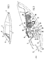
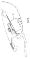
- the section of a passenger car shown in FIG. 1 has a folding roof 2 above a belt line 1, which in its closed position A extends between a windshield frame 3 and a rear area 4 and is detachably held in position on the windshield frame 3.
- the windshield frame 3 is composed of two profile parts 5 and 6, which are connected to one another by flanges 7 and 8, respectively, by welding (FIG. 3).
- the transverse front frame part 10 is composed of pressed sheet metal parts 12, 13 which are connected to one another by welding, gluing or the like (FIG. 6).
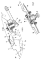
- a locking device 14 which essentially consists of a central actuating device 15, two laterally external locking members 16 and two receptacles 17 arranged on the windshield frame 3 (FIGS. 2 and 3).
- the receptacle 17, which is only accessible from above, is formed by a locking part 18 fastened to the windshield frame 3, to which a locally horizontally aligned bolt 19, which runs approximately in the longitudinal direction of the vehicle, is attached and which can be moved linearly with one in the transverse direction of the vehicle when the folding top 2 is opened and closed guided locking hook 20 of the locking member 16 in Active connection is established.
- the closing part 18 is fastened to an upright flange 21 of the profile part 6 and has two - viewed in the longitudinal direction - spaced, transverse walls 22, 23, between which the bolt 19 extends (FIG. 3). The end of the bolt 19 is guided through both walls 22, 23 and is firmly connected to them (for example by riveting).
- a free space 26 for receiving and for moving the locking hook 20 in a straight line in the transverse direction of the vehicle.
- the free space 26 is open at the top and bottom (FIG. 3).
- the receptacle 17 on the windshield frame 3 is covered from below and from the front by a cladding 24, the end face 25 of the cladding 24 facing away from the windshield 9 being pulled up approximately to the flange 8 of the windshield frame 3.
- the two external locking members 16, the central actuating device 15 and the intermediate connecting elements 27 are combined to form a prefabricated functional unit 28 which is assigned to a common carrier plate 29.
- the carrier plate 29 extends over the substantial part of the width of the folding top 2 and is fastened to the front frame part 10 of the folding top 2 by screws or the like.
- the locking hook 20 is formed in one piece with a slide 30, which sits on two spaced-apart, rectified pipe guides 31, 32 and can be displaced to a limited extent in the vehicle transverse direction BB.
- the locking hook 20 is formed by an approximately vertically extending, downward shaping 33 of the approximately horizontally oriented slide 30.
- the molded part 33 is arranged on the side of the slide 30 facing the receptacle 17 and projects into the free space 26 of the receptacle 17. According to FIG. 3, the molding projects beyond the closing part 18 by a small amount.
- the locking hook 20 extends in the vehicle transverse direction and has one Elongated horizontally aligned slot guide 51, in which the bolt 19 is when the convertible top 2 is closed (closed position A).
- the pipe guides 31, 32 are arranged on a bracket 34 fastened to the carrier plate 29. 5, the transverse pipe guides 31, 32 are received at the end in bearing sections 35, 36 of the bracket 34, whereas the region of the pipe guides 31, 32 between them runs at a distance from a bottom section 37 of the bracket 34.
- the carriage 30 is seated on the pipe guides 31, 32 by means of bearing bushes 38, 39. Furthermore, each carriage 30 is connected to the actuating device 15 via the connecting element 27.
- the connecting element 27 is formed by a pull rod 40 which is connected on the one hand to the slide 30 and on the other hand to a turnstile 41 of the actuating device 15.
- the pull rod 40 is passed locally through a rectangular recess 42 in the support plate 29.
- the connection between tie rod 40 and slide 30 takes place according to FIG. 3 via a ball head connection. However, there is also the possibility of connecting the pull rod 40 to the slide 30 via another articulated connection.
- the carriage 30 with the locking hook 20 is located adjacent to the inner bearing section 35 of the bracket 34, whereas in the unlocked position D of the locking device 14, the carriage 30 runs adjacent to the other outer bearing section 36 (position 30 ').
- On the bracket 34 there is also a downwardly projecting centering pin 43 which, with a corresponding opening 44 in the receptacle 17, forms a centering device 45 for the folding top 2.
- Conical end portions of the centering pin 43 and the opening 44 facilitate the insertion of the Centering pin 43, whereas in the locking position there is a play-free seat of the centering pin 43 in the opening 44.
- a cylindrical collar of the centering pin 43 interacts positively with a corresponding cylindrical section of the opening 44.
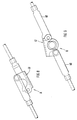
- the actuating device 15 consists of a rotatable and pivotable handle 46 which is connected to the turnstile 41 via a bearing 47.
- the folding top 2 is pulled down by the bow-shaped handle 46, the folding top 2 is locked, and then the handle 46 is pivoted up into a lowered rest position, thereby achieving good ease of use.
- the unlocked position D (Fig. 9)
- the tie rods 40 assume their extended position.
- the locked position A of the tie rods 40 and the turnstile 41 is shown in Fig. 8.
- the folding top 2 is locked, there is a triple safeguard against loosening of the locking device 14. Due to the horizontal alignment of the elongated slot opening 51, no horizontal forces occur, i.e.
- the handle 46 also has an over-center position, thereby preventing the locking device (14) from being released.
- the bow-shaped handle (46) can not be rotated in the folded up rest position.
- the locking device 14 is actuated by a motor.
- the front frame part 10 is provided in a laterally outer area in the electric motor 48 with a gear which interacts via a flexible shaft 49 with a worm gear 50 of the actuating device 15 arranged in the center (FIGS. 11 and 12).
Description
Die Erfindung bezieht sich auf eine Verriegelungsvorrichtung für ein Verdeck am Windschutzscheibenrahmen eines Kraftfahrzeuges gemäß dem Oberbegriff des Anspruches 1.The invention relates to a locking device for a roof on the windshield frame of a motor vehicle according to the preamble of claim 1.
Aus der US-A- 2 831 718 ist eine Verriegelungsvorrichtung für ein Verdeck bekannt, wobei ein vorderes Rahmenteil des Verdecks unter Zwischenschaltung eines Dichtkörpers unmittelbar auf der horizontal verlaufenden Oberseite des Windschutzscheibenrahmens aufliegt und diesen vollständig abdeckt. Die Verriegelungsvorrichtung für das Klappverdeck umfaßt mehrere am Windschutzscheibenrahmen angebrachte, nach oben hin abstehende Halter, wobei jeder Halter seitlich eine Ausnehmung für ein Verriegelungsorgan aufweist. Jedes Verriegelungsorgan wird durch ein um eine vertikale Achse drehbares Bauteil gebildet, wobei beim Schließvorgang des Verdecks der obere Rand eines bogenförmigen, aufrechten Nockens mit einer benachbarten Begrenzungsfläche der Ausnehmung zusammenwirkt. Das Verriegelungsorgan ist über Stangen mit einer zentralen Betätigungseinrichtung verbunden.From US-A-2 831 718 a locking device for a convertible top is known, wherein a front frame part of the convertible top rests directly on the horizontally extending upper side of the windshield frame with the interposition of a sealing body and completely covers it. The locking device for the folding top comprises a plurality of holders which are attached to the windshield frame and project upwards, each holder having a recess for a locking member on the side. Each locking element is formed by a component which can be rotated about a vertical axis, the upper edge of an arched, upright cam interacting with an adjacent boundary surface of the recess when the top is closed. The locking member is connected to a central actuating device via rods.
Dieser Verriegelungsvorrichtung haftet der Nachteil an, daß die Montage der Verriegelungsvorrichtung aufwendig ist, da die einzelnen Teile lagerichtig am Windschutzscheibenrahmen und am vorderen Dachrahmen befestigt und miteinander verbunden werden müssen, um eine einwandfreie Funktion zu gewährleisten. Ferner lassen sich mit dieser Verriegelungsvorrichtung nur geringe senkrechte Hubbewegungen realisieren, d.h., das Klappverdeck muß mit erheblichem Kraftaufwand von Hand relativ weit nach oben gezogen werden, bis der Nocken in die Ausnehmung des Halters eingreift. Der in den Fahrgastraum hineinragende Betätigungsgriff und die bei geöffneten Klappverdeck vorstehenden Halter am Windschutzscheibenrahmen stellen ein beträchtliches Verletzungsrisiko für den Fahrzeugbenutzer dar.This locking device has the disadvantage that the assembly of the locking device is complex, since the individual parts must be fixed in the correct position on the windshield frame and on the front roof frame and connected to one another in order to ensure proper functioning. Furthermore, with this locking device only slight vertical lifting movements can be realized, i.e. the folding top has to be pulled up relatively far by hand with considerable effort until the cam engages in the recess of the holder. The operating handle protruding into the passenger compartment and the brackets on the windshield frame protruding when the folding top is open represent a considerable risk of injury to the vehicle user.
Aufgabe der Erfindung ist es, eine Verriegelungsvorrichtung nach dem Oberbegriff zwischen dem Windschutzscheibenrahmen und einem vorderen Rahmenteil des Verdecks zu schaffen, die bei einfacher Montage eine gute Funktion aufweist und mit der große Hubbewegungen in senkrechter Richtung erzielbar sind. Ferner sollen Verletzungen durch Bauteile der Verriegelungsvorrichtung für die Fahrzeugbenutzer vermieden werden.The object of the invention is to provide a locking device according to the preamble between the windshield frame and a front frame part of the convertible top, which has a good function with simple assembly and with the large lifting movements in the vertical direction are achievable. Furthermore, injuries caused by components of the locking device for vehicle users are to be avoided.
Erfindungsgemäß wird diese Aufgabe durch die kennzeichnenden Merkmale des Anspruchs 1 gelöst. Weitere, die Erfindung in vorteilhafter Weise ausgestaltende Merkmale enthalten die Unteransprüche.According to the invention, this object is achieved by the characterizing features of claim 1. Further features which advantageously design the invention contain the subclaims.
Die mit der Erfindung hauptsächlich erzielten Vorteile sind darin zu sehen, daß die durch einen längsgerichteten Bolzen eines Schließteils und einen in Querrichtung bewegbaren mit einem Schlitten zusammenwirkenden Verriegelungshaken gebildete Verriegelungsvorrichtung im Aufbau einfach ist und eine gute Funktion aufweist. Durch die Ausgestaltung des Verriegelungshakens ist eine relativ große Hubbewegung in senkrechter Richtung erzielbar.The main advantages achieved by the invention can be seen in that the locking device formed by a longitudinal bolt of a locking part and a transversely movable locking hook cooperating locking hook is simple in construction and has a good function. Due to the design of the locking hook, a relatively large stroke movement in the vertical direction can be achieved.
Ferner wird durch die fast vollständige Verkleidung der Aufnahme und der verdeckseitigen Bauteile der Verriegelungsvorrichtung das Verletzungsrisiko der Fahrzeuginsassen auch bei geöffnetem Verdeck wesentlich reduziert. Durch die Zusammenfassung der seitlich außenliegenden Verriegelungsorgane und der zentralen Betätigungseinrichtung auf einer gemeinsamen Trägerplatte wird die Montage der Verriegelungsvorrichtung am vorderen Rahmenteil des Verdecks wesentlich vereinfacht. Aufgrund der doppelten Rohrführung für den Schlitten wird eine stabile Verriegelungsvorrichtung geschaffen, mit der relativ große Kräfte aufgenommen werden können.Furthermore, the almost complete covering of the receptacle and the convertible top components of the locking device substantially reduces the risk of injury to the vehicle occupants even when the convertible top is open. The assembly of the locking device on the front frame part of the convertible top is considerably simplified by the combination of the laterally external locking members and the central actuating device on a common carrier plate. Due to the double pipe guide for the carriage, a stable locking device is created with which relatively large forces can be absorbed.
Ein Ausführungsbeispiel der Erfindung ist in der Zeichnung dargestellt und wird im folgenden näher erläutert.An embodiment of the invention is shown in the drawing and is explained in more detail below.
Es zeigt
- Fig. 1
- eine Ieilseitenansicht eines Personenwagens mit einem Klappverdeck,
- Fig. 2
- eine Draufsicht auf eine Verriegelungsvorrichtung für das Klappverdeck und den angrenzenden Aufbau,
- Fig. 3
- einen Schnitt nach der Linie III-III der Fig. 2,
- Fig. 4
- einen Schnitt nach der Linie IV-IV der Fig. 2,
- Fig. 5
- einen Schnitt nach der Linie V-V der Fig. 4,
- Fig. 6
- einen Schnitt nach der Linie VI-VI der Fig. 2,
- Fig. 7
- einen Schnitt nach der Linie VII-VII der Fig. 6,
- Fig. 8
- eine Ansicht in Pfeilrichtung R der Fig. 7 in der Verriegelungsstellung,
- Fig. 9
- eine Ansicht in Pfeilrichtung R der Fig. 7 in der Entriegelungsstellung,
- Fig. 10
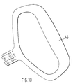
- eine Ansicht in Pfeilrichtung S der Fig. 6,
- Fig. 11
- eine Ansicht entsprechend Fig. 2 mit einer weiteren Ausführungsform der Verriegelungsvorrichtung,
- Fig. 12
- einen Schnitt der Linie XII-XII der Fig. 11.
- Fig. 1
- a side view of a passenger car with a folding top,
- Fig. 2
- a plan view of a locking device for the folding top and the adjacent structure,
- Fig. 3
- 2 shows a section along the line III-III of FIG. 2,
- Fig. 4
- 2 shows a section along the line IV-IV of FIG. 2,
- Fig. 5
- 4 shows a section along the line VV of FIG. 4,
- Fig. 6
- 3 shows a section along the line VI-VI of FIG. 2,
- Fig. 7
- 6 shows a section along line VII-VII of FIG. 6,
- Fig. 8
- 7 in the locking position,
- Fig. 9
- 7 in the unlocking position,
- Fig. 10
- 6 shows a view in the direction of arrow S in FIG. 6,
- Fig. 11
- 2 with a further embodiment of the locking device,
- Fig. 12
- a section of the line XII-XII of Fig. 11th
Der in Fig. 1 dargestellte Teilbereich eines Personenwagens weist oberhalb einer Gürtellinie 1 ein Klappverdeck 2 auf, das sich in seiner Schließstellung A zwischen einem Windschutzscheibenrahmen 3 und einem Heckbereich 4 erstreckt und lösbar am Windschutzscheibenrahmen 3 in Lage gehalten ist. Der Windschutzscheibenrahmen 3 setzt sich aus zwei Profilteilen 5 und 6 zusammen, die an gleichgerichteten Flanschen 7 bzw. 8 durch Schweißen miteinander verbunden sind (Fig. 3).The section of a passenger car shown in FIG. 1 has a
Auf dem einer Windschutzscheibe 9 abgekehrten Flansch 8 des Windschutzscheibenrahmens 3 liegt ein Randbereich eines vorderen Rahmenteiles 10 des Klappverdecks 2 unter Vermittlung eines Dichtkörpers 11 auf. Das querverlaufende, vordere Rahmenteil 10 setzt sich aus Blechpreßteilen 12, 13 zusammen, die durch Schweißen, Kleben oder dgl. miteinander verbunden sind (Fig. 6).On the
Zur Fixierung des Klappverdecks 2 am Windschutzscheibenrahmen 3 ist eine Verriegelungsvorrichtung 14 vorgesehen, die im wesentlichen aus einer zentralen Betätigungseinrichtung 15, zwei seitlich außenliegenden Verriegelungsorganen 16 und und zwei am Windschutzscheibenrahmen 3 angeordneten Aufnahmen 17 besteht (Fig. 2 und 3).To fix the folding top 2 to the
Die lediglich von oben her zugängliche Aufnahme 17 wird durch ein am Windschutzscheibenrahmen 3 befestigtes Schließteil 18 gebildet, an dem örtlich ein etwa horizontal ausgerichteter, annähernd in Fahrzeuglängsrichtung verlaufender Bolzen 19 angebracht ist, der beim Öffnen und Schließen des Klappverdecks 2 mit einem in Fahrzeugquerrichtung linear verschiebbar geführten Verriegelungshaken 20 des Verriegelungsorganes 16 in Wirkverbindung steht. Das Schließteil 18 ist an einem aufrechten Flansch 21 des Profilteiles 6 befestigt und weist zwei - in Längsrichtung gesehen - beabstandete, querverlaufende Wände 22, 23 auf, zwischen denen sich der Bolzen 19 erstreckt (Fig. 3). Der Bolzen 19 ist endseitig durch beide Wände 22, 23 hindurchgeführt und mit diesen fest verbunden (beispielsweise durch Vernieten).The
Zwischen den Wänden 22, 23 erstreckt sich - in Querrichtung gesehen - ein Freiraum 26 zur Aufnahme und zum geradlinigen Bewegen des Verriegelungshakens 20 in Fahrzeugquerrichtung. Der Freiraum 26 ist nach oben und unten hin offen (Fig. 3).Between the
Die Aufnahme 17 am Windschutzscheibenrahmen 3 ist von unten und von vorne her durch eine Verkleidung 24 abgedeckt, wobei die der Windschutzscheibe 9 abgekehrte Stirnseite 25 der Verkleidung 24 etwa bis zum Flansch 8 des Windschutzscheibenrahmens 3 hochgezogen ist.The
Gemäß Fig. 2 sind die beiden außenliegenden Verriegelungsorgane 16, die mittige Betätigungseinrichtung 15 sowie die dazwischenliegenden Verbindungselemente 27 zu einer vorgefertigten funktionsfähigen Baueinheit 28 zusammengefaßt, die einer gemeinsamen Trägerplatte 29 zugeordnet ist. Die Trägerplatte 29 erstreckt sich über den wesentlichen Teil der Breite des Klappverdecks 2 und ist am vorderen Rahmenteil 10 des Klappverdecks 2 durch Schrauben oder dgl. befestigt. Es besteht aber auch die Möglichkeit, die Bauteile der Verriegelungsvorrichtung 14 einzeln am vorderen Rahmenteil 10 des Klappverdecks 2 zu befestigen und auf die Trägerplatte 29 zu verzichten.2, the two
Der Verriegelungshaken 20 ist einstückig mit einem Schlitten 30 ausgebildet, der auf zwei mit Abstand zueinander angeordneten, gleichgerichteten Rohrführungen 31, 32 sitzt und in begrenztem Umfang in Fahrzeugquerrichtung B-B verschiebbar ist. Gemäß Fig. 3 wird der Verriegelungshaken 20 durch eine etwa vertikal verlaufende, nach unten gerichtete Anformung 33 des annähernd horizontal ausgerichteten Schlittens 30 gebildet. Die Anformung 33 ist auf der der Aufnahme 17 zugekehrten Seite des Schlittens 30 angeordnet und ragt in den Freiraum 26 der Aufnahme 17 hinein. Gemäß Fig. 3 überragt die Anformung das Schließteil 18 nach unten hin um einen geringen Betrag. Der Verriegelungshaken 20 erstreckt sich in Fahrzeugquerrichtung und weist eine längliche horizontal ausgerichtete Schlitzführung 51 auf, in der sich der Bolzen 19 bei geschlossenem Klappverdeck 2 (Schließstellung A) befindet. Durch die horizontale Ausrichtung der Schlitzführung 51 sind bei verriegeltem Klappverdeck 2 keine Horizontalkräfte wirksam, sondern nur eine nach oben gerichtete unendlich große Kraft. Der einseitig offenen Schlitzöffnung 51 vorgelagert ist eine schiefe Ebene 52 bzw. ein bogenförmiger nach unten gerichteter Bahnabschnitt, der mit dem Bolzen 19 beim Öffnen und Schließen des Klappverdecks 2 zusammenwirkt. Durch die schiefe Ebene 52 bzw. den gebogenen Bahnabschnitt wird das Klappverdeck 2 beim Schließen um den Hub H nach unten gezogen (Fig. 5). Die offene Seite der Schlitzöffnung 51 ist der Fahrzeuglängsmittelebene C-C zugekehrt.The locking
Die Rohrführungen 31, 32 sind an einer an der Trägerplatte 29 befestigten Konsole 34 angeordnet. Entsprechend Fig. 5 sind die querverlaufenden Rohrführungen 31, 32 endseitig in Lagerabschnitten 35, 36 der Konsole 34 aufgenommen, wogegen der dazwischenliegende Bereich der Rohrführungen 31, 32 mit Abstand zu einem Bodenabschnitt 37 der Konsole 34 verläuft. Der Schlitten 30 sitzt unter Vermittlung von Lagerbuchsen 38, 39 auf den Rohrführungen 31, 32. Ferner ist jeder Schlitten 30 über das Verbindungselement 27 mit der Betätigungseinrichtung 15 verbunden. Das Verbindungselement 27 wird durch eine Zugstange 40 gebildet, welche einerseits an den Schlitten 30 und andererseits an ein Drehkreuz 41 der Betätigungseinrichtung 15 angeschlossen ist. Die Zugstange 40 ist örtlich durch eine rechteckförmige Ausnehmung 42 der Trägerplatte 29 hindurchgeführt. Die Verbindung zwischen Zugstange 40 und Schlitten 30 erfolgt gemäß Fig. 3 über eine Kugelkopfverbindung. Es besteht aber auch die Möglichkeit, die Zugstange 40 über eine andere gelenkige Verbindung an den Schlitten 30 anzuschließen.The pipe guides 31, 32 are arranged on a
In der Schließstellung A befindet sich der Schlitten 30 mit dem Verriegelungshaken 20 benachbart dem innenliegenden Lagerabschnitt 35 der Konsole 34, wogegen in der Entriegelungsstellung D der Verriegelungsvorrichtung 14 der Schlitten 30 benachbart dem anderen äußeren Lagerabschnitt 36 verläuft (Stellung 30'). An der Konsole 34 ist ferner ein nach unten ragender Zentrierzapfen 43 angeordnet, der mit einer korrespondierenden Öffnung 44 der Aufnahme 17 eine Zentriereinrichtung 45 für das Klappverdeck 2 bildet. Konisch ausgebildete Endabschnitte des Zentrierzapfens 43 und der Öffnung 44 erleichtern das Einführen des Zentrierzapfens 43, wogegen in der Arretierstellung ein spielfreier Sitz des Zentnerzapfens 43 in der Öffnung 44 gegeben ist. In der Arretierstellung wirkten ein zylindrischer Bund des Zentrierzapfens 43 mit einem korrespondierend zylindrischen Abschnitt der Öffnung 44 formschlüssig zusammen.In the closed position A, the
Beim Verriegeln des Klappverdecks 2 bewegt sich der Schlitten 30 mit dem Verriegelungshaken 20 von außen nach innen (Weg s).When the folding top 2 is locked, the
Gemäß einer ersten Ausführungsform (Fig. 6) besteht die Betätigungseinrichtung 15 aus einem dreh- und schwenkbaren Handgriff 46, der über eine Lagerung 47 mit dem Drehkreuz 41 verbunden ist. Mit einer Hand wird das Klappverdeck 2 durch den bügelförmigen Handgriff 46 nach unten gezogen, das Klappverdeck 2 verriegelt und anschließend der Handgriff 46 in eine versenkte Ruhestellung hochgeschwenkt, wodurch ein guter Bedienungskomfort erzielt wird. In der entriegelten Stellung D (Fig. 9) nehmen die Zugstangen 40 ihre gestreckte Lage ein. Die verriegelte Stellung A der Zugstangen 40 bzw. des Drehkreuzes 41 ist in Fig. 8 dargestellt. Bei verriegeltem Klappverdeck 2 ist eine dreifache Sicherung gegen ein Lösen der Verriegelungsvorrichtung 14 vorhanden. Durch die horizontale Ausrichtung der länglichen Schlitzöffnung 51 treten keine horizontalen Kräfte auf, d.h. alle Bauteile der Verriegelungsvorrichtung 14 sind im Verriegelungszustand spannungslos. Ferner weist der Handgriff 46 in der Verriegelungsstellung eine Übertotpunktlage ein, wodurch ein Lösen der Verriegelungsvorrichtung (14) vermieden wird. Außerdem läßt sich der bügelförmige Handgriff (46) in der hochgeklappten Ruhestellung nicht verdrehen.According to a first embodiment (FIG. 6), the
Bei einer zweiten Ausführungsform wird die Verriegelungsvorrichtung 14 motorisch betätigt. Hierzu ist am vorderen Rahmenteil 10 und zwar in einem seitlich außenliegenden Bereich in Elektromotor 48 mit einem Getriebe vorgesehen, der über eine biegsame Welle 49 mit einem Schneckengetriebe 50 der mittig angeordneten Betätigungseinrichtung 15 zusammenwirkt (Fig. 11 und 12).In a second embodiment, the locking
Claims (15)
- A device for locking a top on the windscreen frame (3) of a motor vehicle, in particular for a folding top (2), comprising a central actuating device (15) which is arranged on a front frame part (10) of the top (2) substantially in the region of a longitudinal median plane of the vehicle and which is attached by way of transversely extending connecting members (27) to locking members (16) situated laterally on the outside, wherein the locking members (16) cooperate with receiving means mounted on the windscreen frame (3) when the top is closed, characterized in that the receiving means (17) accessible only from above is formed by a closure part (18) which is secured to the windscreen frame (3) and on which a pin (19) orientated substantially horizontally and extending substantially in the longitudinal direction of the vehicle is formed locally, wherein the pin (19) is operatively connected during the opening and closing of the folding top (2) to a locking hook (20) of the locking member (16) projecting into the closure part (18) and guided displaceably in the transverse direction of the vehicle.
- A locking device according to Claim 1, characterized in that the pin (19) is mounted on two spaced, transversely extending walls (22, 23) of the closure part (18).
- A locking device according to Claim 1, characterized in that a free space (26) is provided between the two spaced walls (22, 23) as viewed in the transverse direction for the insertion and movement of the locking hook (20).
- A locking device according to Claim 1, characterized in that a covering (24) for the windscreen frame (3) extends along an underside and a vertical front face of the windscreen frame (3).
- A locking device according to Claim 1, characterized in that the two locking members (16) situated laterally on the outside, the central actuating device (15) and the connecting members (27) form a prefabricated, operatively viable structural unit (28) mounted on a common support plate (29).
- A locking device according to Claim 1, characterized in that the locking hook (20) is integral with a slide (30).
- A locking device according to Claim 6, characterized in that the locking hook (20) is formed by an integral attachment (33) - extending substantially vertically - of the slide (30) orientated substantially horizontally, wherein the integral attachment (33) is mounted on the side of the slide (30) facing the receiving means (17).
- A locking device according to Claim 6, characterized in that the slide (30) rests on two tubular guides (31, 32) orientated in the same direction and arranged at a distance from each other and is displaceable to a limited extent in the transverse direction B-B of the vehicle.
- A locking device according to Claim 8, characterized in that the tubular guides (31, 32) are mounted on a bracket (34) of the locking member (16) which is secured to the support plate (29).
- A locking device according to Claim 6, characterized in that each slide (30) is connected to the central actuating device (15) by way of a connecting member (27) formed by a connecting rod (40).
- A locking device according to Claim 1, characterized in that the locking hook (30) comprises an elongate slot opening (51) open on one side and having mounted in front thereof a downwardly directed inclined plane (52) or a path portion bent into a curve, wherein when the folding top (2) is closed the pin (19) extends inside the horizontally orientated elongate slot opening and rests against the locking hook (20).
- A locking device according to Claim 11, characterized in that the open side of the slot opening (51) faces the longitudinal median plane of the vehicle.
- A locking device according to Claim 1, characterized in that in addition to the locking device (14) a centring device (45) is provided for the folding top (2), the centring device (45) being formed by a downwardly projecting centring pin (43) attached to the bracket (34) and engaging in a corresponding opening (44) in the receiving means (17).
- A locking device according to Claim 6, characterized in that the connecting rods (40) are connected in a rotatable manner to a rotary star (41) of the actuating device (15), wherein the rotary star (41) is mounted on the side of the actuating device (15) remote from a handle (46), namely inside the frame part (10).
- A locking device according to Claim 1, characterized in that when the folding top (2) is locked the locking hooks (20) move inwards from the outside around the path S and engage around the pin (19).
Applications Claiming Priority (2)
| Application Number | Priority Date | Filing Date | Title |
|---|---|---|---|
| DE3940839A DE3940839C1 (en) | 1989-12-11 | 1989-12-11 | |
| DE3940839 | 1989-12-11 |
Publications (3)
| Publication Number | Publication Date |
|---|---|
| EP0432375A2 EP0432375A2 (en) | 1991-06-19 |
| EP0432375A3 EP0432375A3 (en) | 1992-08-12 |
| EP0432375B1 true EP0432375B1 (en) | 1994-04-13 |
Family
ID=6395210
Family Applications (1)
| Application Number | Title | Priority Date | Filing Date |
|---|---|---|---|
| EP90116959A Expired - Lifetime EP0432375B1 (en) | 1989-12-11 | 1990-09-04 | Locking device for a folding top |
Country Status (3)
| Country | Link |
|---|---|
| US (1) | US5042869A (en) |
| EP (1) | EP0432375B1 (en) |
| DE (2) | DE3940839C1 (en) |
Families Citing this family (28)
| Publication number | Priority date | Publication date | Assignee | Title |
|---|---|---|---|---|
| FI91227C (en) * | 1991-10-17 | 1994-06-10 | Saab Valmet Ab Oy | Locking device for locking the roof of an open car |
| GB2267063B (en) * | 1992-05-14 | 1995-12-06 | Ford Motor Co | A folding roof assembly |
| US5624149A (en) * | 1992-09-04 | 1997-04-29 | Asc Incorporated | Apparatus and method for securing a convertible roof to an automotive vehicle |
| US5284378A (en) * | 1992-11-16 | 1994-02-08 | Wickes Manufacturing Company | Self-storing convertible top latch system |
| DE4303284C1 (en) * | 1993-02-05 | 1994-06-01 | Daimler Benz Ag | Adjusting system for fastener parts, esp. hood fasteners of convertible - has one fastener part fixed on frame and other fastener part fitted at counter structural part moving relative to frame |
| DE4312323C1 (en) * | 1993-04-15 | 1994-07-07 | Daimler Benz Ag | Locking arrangement for fixing a pivotable cover on a counterpart of a vehicle body |
| FI98140C (en) * | 1994-01-26 | 1997-04-25 | Valmet Automotive Oy | Convertible sunroof locking arrangement |
| US5755467A (en) * | 1995-01-31 | 1998-05-26 | Asc Incorporated | Latching and switch operating system for a convertible roof |
| DE19507431C1 (en) * | 1995-03-03 | 1996-08-01 | Daimler Benz Ag | Hardtop vehicle |
| DE19608495C2 (en) * | 1995-06-17 | 2003-12-11 | Edscha Cabrio Dachsys Gmbh | locking device |
| DE29622540U1 (en) * | 1996-12-30 | 1998-04-30 | Karmann Gmbh W | Locking device for a convertible top |
| DE19734671C2 (en) * | 1997-08-11 | 1999-10-21 | Daimler Chrysler Ag | Folding roof arrangement for a motor vehicle with a folding cover |
| US6042174A (en) * | 1997-08-22 | 2000-03-28 | Asc Incorporated | Latching and control apparatus for an automotive vehicle convertible roof |
| DE29717325U1 (en) * | 1997-09-27 | 1998-07-16 | Karmann Gmbh W | Cabriolet vehicle |
| DE19810022C1 (en) * | 1998-03-09 | 1999-06-17 | Cts Fahrzeug Dachsysteme Gmbh | Hood for open top motor vehicle |
| US5998948A (en) * | 1998-05-29 | 1999-12-07 | Acs Incorporated | Convertible roof actuation mechanism |
| US6290281B1 (en) | 1999-05-26 | 2001-09-18 | Asc Incorporated | Power latch for an automotive vehicle convertible roof system |
| DE19960022C1 (en) * | 1999-12-13 | 2001-06-07 | Edscha Cabrio Verdecksys Gmbh | Safety system for the release lock at the roof of a convertible automobile has a signal generator which blocks the hand grip movement on an accidental opening action |
| DE19962069B4 (en) * | 1999-12-22 | 2004-08-12 | Edscha Cabrio-Dachsysteme Gmbh | Locking device for vehicle tops |
| DE10023844C1 (en) * | 2000-05-16 | 2001-10-31 | Webasto Vehicle Sys Int Gmbh | Opening roof for vehicle has roof element, front edge of which moves tangentially to outer skin of roof |
| US6767047B2 (en) * | 2002-08-15 | 2004-07-27 | Asc Incorporated | Convertible roof latch |
| US6837535B2 (en) * | 2002-08-15 | 2005-01-04 | Asc Incorporated | Convertible roof system |
| US7021696B2 (en) | 2002-11-14 | 2006-04-04 | Asc Incorporated | Convertible top latch |
| DE10300883B3 (en) * | 2003-01-13 | 2004-03-11 | Dr.Ing.H.C. F. Porsche Ag | Cover for closure for cabriolet vehicle roof has cover shell housing secured to closure via holder with ratchet openings for locating ratchet noses of closure |
| DE10308770B4 (en) * | 2003-02-28 | 2005-07-21 | Dr.Ing.H.C. F. Porsche Ag | Closure for a removable roof |
| WO2005084290A2 (en) * | 2004-02-27 | 2005-09-15 | Cts Fahrzeug Dachsysteme Gmbh | Latching system for a convertible top |
| US7559585B2 (en) * | 2004-08-20 | 2009-07-14 | Wilhelm Karmann Gmbh | Support frame for header latch assembly |
| US9027685B2 (en) * | 2013-03-14 | 2015-05-12 | Mattel, Inc. | Latch assemblies and children's products that include latch assemblies |
Family Cites Families (14)
| Publication number | Priority date | Publication date | Assignee | Title |
|---|---|---|---|---|
| US1174366A (en) * | 1914-06-01 | 1916-03-07 | Antoine Van Den Plas | Door-locking mechanism. |
| US2486905A (en) * | 1946-01-17 | 1949-11-01 | John W J Ackermans | Convertible top latching means |
| US2560459A (en) * | 1947-09-10 | 1951-07-10 | Briggs Mfg Co | Locking mechanism for convertible tops |
| US2570261A (en) * | 1948-07-01 | 1951-10-09 | Jacobs Co F L | Header locking mechanism |
| US2586648A (en) * | 1948-11-12 | 1952-02-19 | Detroit Harvester Co | Locking mechanism for folding tops |
| DE836291C (en) * | 1950-10-08 | 1952-04-10 | Hugo Niehaus | Closure for the convertible top |
| US2831718A (en) * | 1955-01-11 | 1958-04-22 | Gen Motors Corp | Convertible top header lock assembly |
| US2852292A (en) * | 1956-03-14 | 1958-09-16 | Ford Motor Co | Convertible top power header lock |
| US3089719A (en) * | 1960-07-22 | 1963-05-14 | Dura Corp | Power operated latch for convertible tops |
| US3353864A (en) * | 1965-10-23 | 1967-11-21 | Gen Motors Corp | Convertible top latch mechanism |
| US3425742A (en) * | 1967-08-08 | 1969-02-04 | Benjamin Thomas Rauber Jr | Locking means for locking the top of a convertible automobile |
| DE3413379C2 (en) * | 1984-04-10 | 1986-02-13 | Dr.Ing.H.C. F. Porsche Ag, 7000 Stuttgart | Locking device for a convertible top on the windshield frame of a motor vehicle |
| DE3715764A1 (en) * | 1987-05-12 | 1988-11-24 | Porsche Ag | LOCKING DEVICE FOR A CANOPY ON THE WINDSHIELD FRAME OF A MOTOR VEHICLE |
| US4830425A (en) * | 1988-01-04 | 1989-05-16 | Muscat Peter P | Latching system for a convertible top |
-
1989
- 1989-12-11 DE DE3940839A patent/DE3940839C1/de not_active Expired - Lifetime
-
1990
- 1990-09-04 DE DE59005356T patent/DE59005356D1/en not_active Expired - Fee Related
- 1990-09-04 EP EP90116959A patent/EP0432375B1/en not_active Expired - Lifetime
- 1990-11-27 US US07/619,933 patent/US5042869A/en not_active Expired - Fee Related
Also Published As
| Publication number | Publication date |
|---|---|
| DE3940839C1 (en) | 1991-01-31 |
| EP0432375A2 (en) | 1991-06-19 |
| EP0432375A3 (en) | 1992-08-12 |
| DE59005356D1 (en) | 1994-05-19 |
| US5042869A (en) | 1991-08-27 |
Similar Documents
| Publication | Publication Date | Title |
|---|---|---|
| EP0432375B1 (en) | Locking device for a folding top | |
| EP0494366B1 (en) | Vehicule roof | |
| DE3413379C2 (en) | Locking device for a convertible top on the windshield frame of a motor vehicle | |
| DE19635869C1 (en) | Folding roof for vehicles | |
| DE3201895A1 (en) | FOLDING COVER FOR A MOTOR VEHICLE, IN PARTICULAR PERSONAL VEHICLES | |
| DE19533802C1 (en) | Hood for a vehicle, in particular a carbriolet | |
| EP0754130A1 (en) | Locking device for detachably securing a vehicle roof to an immovable part of the car body | |
| EP0215220A1 (en) | Seat belt, in particular a 3-point seat belt for vehicles | |
| DE19801852A1 (en) | Locking device for fixing a convertible top | |
| EP1403116B1 (en) | Convertible vehicle with a retractable, foldable soft top | |
| WO2000034078A1 (en) | Loading space covering or rear-window shelf comprising moveable corner pieces | |
| DE4234741A1 (en) | Sun visors for vehicles | |
| EP1708903A1 (en) | Cabriolet | |
| EP1758752B1 (en) | Convertible | |
| DE3211363A1 (en) | Lock for a divided backrest for the rear seats of a motor vehicle | |
| EP0429777A2 (en) | Collapsible hood for a motor car | |
| DE4307158C1 (en) | Folding roof for cabriolet - has angled locating hole for angled plug type catch at bottom of rear frame in erected position | |
| EP1752325A1 (en) | Roof system for a car | |
| DE2747835A1 (en) | VEHICLE BODY WITH A SUN ROOF | |
| EP0379031B1 (en) | Roof luggage case for motor vehicles | |
| DE3311441C2 (en) | Upper ridge sunroof | |
| DE19606605A1 (en) | Vehicle, esp. passenger car | |
| EP0307570B1 (en) | Locking device for a vehicle top | |
| DE3490325T1 (en) | Windshield wiper with wiper joint axis on the arm with cross locking | |
| DE2223208A1 (en) | COVER SUPPORT |
Legal Events
| Date | Code | Title | Description |
|---|---|---|---|
| PUAI | Public reference made under article 153(3) epc to a published international application that has entered the european phase |
Free format text: ORIGINAL CODE: 0009012 |
|
| AK | Designated contracting states |
Kind code of ref document: A2 Designated state(s): DE FR GB IT |
|
| PUAL | Search report despatched |
Free format text: ORIGINAL CODE: 0009013 |
|
| AK | Designated contracting states |
Kind code of ref document: A3 Designated state(s): DE FR GB IT |
|
| 17P | Request for examination filed |
Effective date: 19920923 |
|
| 17Q | First examination report despatched |
Effective date: 19931005 |
|
| ITF | It: translation for a ep patent filed |
Owner name: DE DOMINICIS & MAYER S.R.L. |
|
| GRAA | (expected) grant |
Free format text: ORIGINAL CODE: 0009210 |
|
| AK | Designated contracting states |
Kind code of ref document: B1 Designated state(s): DE FR GB IT |
|
| REF | Corresponds to: |
Ref document number: 59005356 Country of ref document: DE Date of ref document: 19940519 |
|
| GBT | Gb: translation of ep patent filed (gb section 77(6)(a)/1977) |
Effective date: 19940511 |
|
| ET | Fr: translation filed | ||
| PLBE | No opposition filed within time limit |
Free format text: ORIGINAL CODE: 0009261 |
|
| STAA | Information on the status of an ep patent application or granted ep patent |
Free format text: STATUS: NO OPPOSITION FILED WITHIN TIME LIMIT |
|
| 26N | No opposition filed | ||
| PGFP | Annual fee paid to national office [announced via postgrant information from national office to epo] |
Ref country code: GB Payment date: 19980828 Year of fee payment: 9 Ref country code: FR Payment date: 19980828 Year of fee payment: 9 |
|
| PGFP | Annual fee paid to national office [announced via postgrant information from national office to epo] |
Ref country code: DE Payment date: 19980909 Year of fee payment: 9 |
|
| PG25 | Lapsed in a contracting state [announced via postgrant information from national office to epo] |
Ref country code: GB Free format text: LAPSE BECAUSE OF NON-PAYMENT OF DUE FEES Effective date: 19990904 |
|
| GBPC | Gb: european patent ceased through non-payment of renewal fee |
Effective date: 19990904 |
|
| PG25 | Lapsed in a contracting state [announced via postgrant information from national office to epo] |
Ref country code: FR Free format text: LAPSE BECAUSE OF NON-PAYMENT OF DUE FEES Effective date: 20000531 |
|
| PG25 | Lapsed in a contracting state [announced via postgrant information from national office to epo] |
Ref country code: DE Free format text: LAPSE BECAUSE OF NON-PAYMENT OF DUE FEES Effective date: 20000701 |
|
| REG | Reference to a national code |
Ref country code: FR Ref legal event code: ST |
|
| PG25 | Lapsed in a contracting state [announced via postgrant information from national office to epo] |
Ref country code: IT Free format text: LAPSE BECAUSE OF NON-PAYMENT OF DUE FEES Effective date: 20050904 |