EP0431746B2 - Fräswerkzeuge - Google Patents
Fräswerkzeuge Download PDFInfo
- Publication number
- EP0431746B2 EP0431746B2 EP90311838A EP90311838A EP0431746B2 EP 0431746 B2 EP0431746 B2 EP 0431746B2 EP 90311838 A EP90311838 A EP 90311838A EP 90311838 A EP90311838 A EP 90311838A EP 0431746 B2 EP0431746 B2 EP 0431746B2
- Authority
- EP
- European Patent Office
- Prior art keywords
- inserts
- teeth
- cutter
- cutting
- profile
- Prior art date
- Legal status (The legal status is an assumption and is not a legal conclusion. Google has not performed a legal analysis and makes no representation as to the accuracy of the status listed.)
- Expired - Lifetime
Links
Images


Classifications
-
- B—PERFORMING OPERATIONS; TRANSPORTING
- B23—MACHINE TOOLS; METAL-WORKING NOT OTHERWISE PROVIDED FOR
- B23C—MILLING
- B23C5/00—Milling-cutters
- B23C5/02—Milling-cutters characterised by the shape of the cutter
- B23C5/12—Cutters specially designed for producing particular profiles
-
- B—PERFORMING OPERATIONS; TRANSPORTING
- B23—MACHINE TOOLS; METAL-WORKING NOT OTHERWISE PROVIDED FOR
- B23C—MILLING
- B23C5/00—Milling-cutters
- B23C5/16—Milling-cutters characterised by physical features other than shape
- B23C5/20—Milling-cutters characterised by physical features other than shape with removable cutter bits or teeth or cutting inserts
- B23C5/22—Securing arrangements for bits or teeth or cutting inserts
- B23C5/2204—Securing arrangements for bits or teeth or cutting inserts with cutting inserts clamped against the walls of the recess in the cutter body by a clamping member acting upon the wall of a hole in the insert
- B23C5/2226—Securing arrangements for bits or teeth or cutting inserts with cutting inserts clamped against the walls of the recess in the cutter body by a clamping member acting upon the wall of a hole in the insert for plate-like cutting inserts fitted on an intermediate carrier, e.g. shank fixed in the cutter body
-
- B—PERFORMING OPERATIONS; TRANSPORTING
- B23—MACHINE TOOLS; METAL-WORKING NOT OTHERWISE PROVIDED FOR
- B23C—MILLING
- B23C5/00—Milling-cutters
- B23C5/16—Milling-cutters characterised by physical features other than shape
- B23C5/20—Milling-cutters characterised by physical features other than shape with removable cutter bits or teeth or cutting inserts
- B23C5/22—Securing arrangements for bits or teeth or cutting inserts
- B23C5/24—Securing arrangements for bits or teeth or cutting inserts adjustable
- B23C5/2462—Securing arrangements for bits or teeth or cutting inserts adjustable the adjusting means being oblique surfaces
-
- B—PERFORMING OPERATIONS; TRANSPORTING
- B23—MACHINE TOOLS; METAL-WORKING NOT OTHERWISE PROVIDED FOR
- B23F—MAKING GEARS OR TOOTHED RACKS
- B23F21/00—Tools specially adapted for use in machines for manufacturing gear teeth
- B23F21/12—Milling tools
- B23F21/14—Profile cutters of disc type
- B23F21/143—Profile cutters of disc type with inserted cutting elements
- B23F21/146—Profile cutters of disc type with inserted cutting elements in exchangeable arrangement
-
- B—PERFORMING OPERATIONS; TRANSPORTING
- B23—MACHINE TOOLS; METAL-WORKING NOT OTHERWISE PROVIDED FOR
- B23C—MILLING
- B23C2200/00—Details of milling cutting inserts
- B23C2200/36—Other features of the milling insert not covered by B23C2200/04 - B23C2200/32
- B23C2200/367—Mounted tangentially, i.e. where the rake face is not the face with largest area
-
- Y—GENERAL TAGGING OF NEW TECHNOLOGICAL DEVELOPMENTS; GENERAL TAGGING OF CROSS-SECTIONAL TECHNOLOGIES SPANNING OVER SEVERAL SECTIONS OF THE IPC; TECHNICAL SUBJECTS COVERED BY FORMER USPC CROSS-REFERENCE ART COLLECTIONS [XRACs] AND DIGESTS
- Y10—TECHNICAL SUBJECTS COVERED BY FORMER USPC
- Y10T—TECHNICAL SUBJECTS COVERED BY FORMER US CLASSIFICATION
- Y10T407/00—Cutters, for shaping
- Y10T407/17—Gear cutting tool
- Y10T407/1715—Hob
- Y10T407/1725—Hob including holder having seat for inserted tool
-
- Y—GENERAL TAGGING OF NEW TECHNOLOGICAL DEVELOPMENTS; GENERAL TAGGING OF CROSS-SECTIONAL TECHNOLOGIES SPANNING OVER SEVERAL SECTIONS OF THE IPC; TECHNICAL SUBJECTS COVERED BY FORMER USPC CROSS-REFERENCE ART COLLECTIONS [XRACs] AND DIGESTS
- Y10—TECHNICAL SUBJECTS COVERED BY FORMER USPC
- Y10T—TECHNICAL SUBJECTS COVERED BY FORMER US CLASSIFICATION
- Y10T407/00—Cutters, for shaping
- Y10T407/17—Gear cutting tool
- Y10T407/1745—Rotary, tooth form cutting tool
-
- Y—GENERAL TAGGING OF NEW TECHNOLOGICAL DEVELOPMENTS; GENERAL TAGGING OF CROSS-SECTIONAL TECHNOLOGIES SPANNING OVER SEVERAL SECTIONS OF THE IPC; TECHNICAL SUBJECTS COVERED BY FORMER USPC CROSS-REFERENCE ART COLLECTIONS [XRACs] AND DIGESTS
- Y10—TECHNICAL SUBJECTS COVERED BY FORMER USPC
- Y10T—TECHNICAL SUBJECTS COVERED BY FORMER US CLASSIFICATION
- Y10T407/00—Cutters, for shaping
- Y10T407/19—Rotary cutting tool
- Y10T407/1906—Rotary cutting tool including holder [i.e., head] having seat for inserted tool
- Y10T407/1908—Face or end mill
- Y10T407/191—Plural simultaneously usable separable tools in common seat or common clamp actuator for plural simultaneously usable tools
-
- Y—GENERAL TAGGING OF NEW TECHNOLOGICAL DEVELOPMENTS; GENERAL TAGGING OF CROSS-SECTIONAL TECHNOLOGIES SPANNING OVER SEVERAL SECTIONS OF THE IPC; TECHNICAL SUBJECTS COVERED BY FORMER USPC CROSS-REFERENCE ART COLLECTIONS [XRACs] AND DIGESTS
- Y10—TECHNICAL SUBJECTS COVERED BY FORMER USPC
- Y10T—TECHNICAL SUBJECTS COVERED BY FORMER US CLASSIFICATION
- Y10T407/00—Cutters, for shaping
- Y10T407/19—Rotary cutting tool
- Y10T407/1906—Rotary cutting tool including holder [i.e., head] having seat for inserted tool
- Y10T407/1908—Face or end mill
- Y10T407/1912—Tool adjustable relative to holder
- Y10T407/1914—Radially
- Y10T407/1916—And axially
-
- Y—GENERAL TAGGING OF NEW TECHNOLOGICAL DEVELOPMENTS; GENERAL TAGGING OF CROSS-SECTIONAL TECHNOLOGIES SPANNING OVER SEVERAL SECTIONS OF THE IPC; TECHNICAL SUBJECTS COVERED BY FORMER USPC CROSS-REFERENCE ART COLLECTIONS [XRACs] AND DIGESTS
- Y10—TECHNICAL SUBJECTS COVERED BY FORMER USPC
- Y10T—TECHNICAL SUBJECTS COVERED BY FORMER US CLASSIFICATION
- Y10T407/00—Cutters, for shaping
- Y10T407/19—Rotary cutting tool
- Y10T407/1906—Rotary cutting tool including holder [i.e., head] having seat for inserted tool
- Y10T407/1926—Plural simultaneously usable separable tools in common seat or common clamp actuator for plural simultaneously usable tools
-
- Y—GENERAL TAGGING OF NEW TECHNOLOGICAL DEVELOPMENTS; GENERAL TAGGING OF CROSS-SECTIONAL TECHNOLOGIES SPANNING OVER SEVERAL SECTIONS OF THE IPC; TECHNICAL SUBJECTS COVERED BY FORMER USPC CROSS-REFERENCE ART COLLECTIONS [XRACs] AND DIGESTS
- Y10—TECHNICAL SUBJECTS COVERED BY FORMER USPC
- Y10T—TECHNICAL SUBJECTS COVERED BY FORMER US CLASSIFICATION
- Y10T407/00—Cutters, for shaping
- Y10T407/19—Rotary cutting tool
- Y10T407/1952—Having peripherally spaced teeth
- Y10T407/1962—Specified tooth shape or spacing
Definitions
- This invention relates to milling cutters for cutting profile shapes. It is particularly concerned with milling cutters that are provided with replaceable cutting inserts.
- a similar milling cutter has been proposed as a gear hob (GB 1597599) in which a series of reversible cutting inserts are secured to successive teeth of a cutter disc, the inserts being mainly rectangular but at the radially outer tips of the teeth there being circular inserts or inserts with a bulbous curved cutting edge to relieve the gear tooth roots.
- the rotation of the cutter must be coordinated with an indexing motion of the gear being cut.
- the trueness of the profile is plainly limited because finish grinding is recommended for heavy duty gears.
- a milling cutter according to the preamble of claim 1 and a method according to the preamble of claim 8 are known.
- a milling cutter comprising a rotatable body on which there is at least one circumferentially arranged series of teeth carrying cutting inserts, at least some of the teeth having a plurality of said inserts spaced from each other on the periphery of the tooth and the inserts of at least one said tooth of said series being peripherally staggered relative to the inserts on at least one other tooth such that the staggered and spaced inserts have paths of rotation that intersect to form a continuous profile cutting line, a plurality of carriers on the teeth of the rotatable cutter body each providing a common mounting for mounting a plurality of inserts of a respective tooth in said mutually spaced relationship on the body, characterised in that the carriers are adjustable while attached to the teeth and are securable in their positions of adjustment, and in that at least some of the inserts have their cutting edges ground in situ on the teeth to define the profile of said cutting line.
- the inserts can be premounted on them in appropriate relative positions, so simplifying the replacement of the inserts.
- the inserts have a pair of parallel opposite faces one of which provides the clearance face extending rearwards from the cutting edge in the cutting direction and said faces are the major faces of the insert configuration.
- a method of producing a milling cutter for cutting a profiled shape in which a rotatable cutter body has at least one series of teeth around its circumference on which cutting inserts are mounted replaceably, on at least some of the teeth a plurality of said inserts are mounted at spaced intervals and at staggered relative positions on at least one said tooth relative to at least one other said tooth, so that said inserts have intersecting paths of rotation, to form a continuous profile cutting line, at least some of the inserts being mounted in groups on carriers, characterised in that the carriers can be adjusted on respective teeth of the cutter body while attached thereto to set the positions of the inserts on said teeth, said carriers then being secured in their positions of adjustment, and that at least some of said inserts being given profile ground cutting edges, while they are secured in place on the cutter body, to the profile of said cutting line.
- the initial clearance angle at a cutting edge on an insert of a cutter according to the invention is preferably not less than 10° before grinding. Without impairing the security or operation of the insert to any material extent the clearance face can, in fact, be set to a substantially larger clearance angle, eg. over 12°.
- a substantially larger clearance angle eg. over 12°.
- the disc-shaped milling cutter in Figs. 1 and 2 has a conventional bore 102 and keyway 104 to mount it on the arbour of a milling machine. It is fluted at intervals around its periphery to form a series of teeth 106 of identical form, except for the seatings 108 (Fig. 5) which they contain for a series of reversible cutting inserts 110 providing the cutting edges of the tool.
- Figs. 3 and 4 illustrate the two patterns in each of which the inserts are set at spaced intervals around the front face of the tooth.
- the front faces of the inserts lie in radial planes of the cutter disc, ie. at zero radial rake.
- the front faces of the teeth are coincident with the front faces of their inserts.
- the alternate teeth of the cutter disc have the locations of the inserts staggered so that the positions of the inserts of two successive teeth, when combined, make up the overlapping series that appears in Fig. 2.
- the positions of the inserts are so arranged that, in their initial polygonal form, the surfaces of revolution swept by their active cutting edges project beyond the intended profile to be cut. With the inserts in position, the active cutting edges are ground back to the intended profile line, indicated at 112 (Fig. 2). As a result of this and the overlapping of the individual inserts on successive teeth, the precise profile can be milled by the cutter, obviating the need for a further finishing operation. Because the inserts have their cutting edges shaped when they are firmly in place on the milling cutter, accuracy can be ensured.
- the insert illustrated in Fig. 5 before profile grinding has parallel main faces 120,122 of parallelogram shape, front and rear faces 124 inclined inwards from the top face, and side faces 126 perpendicular to the top face, so that the insert is indexable front to rear in its seating. It is secured by a central screw 128.
- the seating has a bottom face 132 that, in a radial plane of the tool, lies at an angle, typically 75°, to a radius passing through its front edge.
- the top or clearance face 120 of the insert thus has a clearance angle, typically 15°.
- the seating may similarly have a side face (not shown) for one side face 126 of the insert so oriented that the exposed opposite side face of the insert lies at a 15° clearance angle also.
- this latter clearance is usually required only for the inserts at the outer tips of the cutter teeth, as can be seen in Figs. 3 and 4.
- Figs. 3 and 4 illustrate by the broken line 136 the contour of the cutter body.
- the clearance faces 120,126 are ground back as required to reform the active cutting edges of the initially polygonal inserts, each face being ground in a plane oblique to its initial clearance angle.
- the grinding cut runs out on the clearance face to leave only a portion of that face from its junction with the cutting edge at a clearance angle substantially less than the 15° angle to which the faces are originally set.
- the run-out of the grinding cut on these faces is preferably a sufficiently small distance from the active cutting edge to allow regrinding of the cutting edges in the same manner, to prolong their use, before the inserts are indexed and the opposite cutting edges formed to the profile by grinding the opposite regions of the clearance faces in the same manner.
- the cutting inserts 140 are not received directly in seatings integral with the teeth 142 at the periphery of the cutter body.
- the inserts 140 are mounted instead in groups of two or more on carriers or shoes 144 that are themselves adjustably secured in slots 146 that are formed integrally in the teeth 142.
- Each slot 146 has a rear face 148 against which the shoe 144 bears. Between the slot rear face and the shoe there is a tenon connection 150 allowing the shoe to slide over the rear face in the axial direction of the tenon.
- the position of adjustment of the shoe 144 on the tenon connection is controlled by a wedge 152 sandwiched between the shoe and bottom face 154 of the slot and displaceable parallel to the bottom face.
- the shoe can be locked in place by one or more clamping wedges 156 adjacent the slot 146 that can be tightened onto the cutter body by screws (not shown).
- the movement of each adjusting wedge is obtained by rotating a pin 160 that is threaded into the cutter body and that has a collar 162 engaging a recess 164 of the wedge so that the wedge moves parallel to the slot rear face 148 as the screw is rotated.
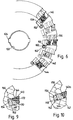
- Figs. 7(a) to (d) and Fig. 9 show the inserts 140 mounted tangentially on the cutter body, similarly to the inserts of the first example, with approximately radially directed clamping screws 170 securing them to their shoe.
- the top face of the insert has a central relief 172 to give a separate top land at each cutting edge which can be ground independently of the other land and without complication from grinding wheel run-out.
- Figs. 8(a)-(d) and Fig. 10 show inserts 140a mounted radially on their shoes, with approximately tangentially directed clamping screws. It will be understood that the original shapes of the inserts may be varied to suit best the particular profiles to be cut, and this example also shows the use of indexable inserts of shapes other than a parallelogram. In other respects the arrangement is identical to that shown in Fig. 7 and 9 and the same reference numbers are used for the same parts.
- Figs. 7 and 8 the composite pattern of insert forming the cutting profile is distributed over four successive teeth 142 of the cutter body, preferably alternating on opposite sides of successive teeth.
- the next tooth will have 5,7, followed by 2,4 and then 6,8.
- Fig. 7 and 8 also illustrate how the individual shoes project axially of the cutter across the maximum radius of the profile.
- FIGs. 7 and 8 Another feature brought out by Figs. 7 and 8 is the orientation of the tenon at an oblique angle to the radial direction.
- each shoe, with its inserts remaining fixed to it is advanced along the tenon and, because of the oblique angle of advance, the amount of material to be ground away can be minimised.
- the substantial overlap of the inserts of different teeth of the pattern at the centre of the profile is able to accommodate the axial movement of the inserts that occurs in this adjustment.
- the angle of obliquity of the tenon to the radial direction will vary with the profile concerned, but for best effect the angle will usually be set at approximately the mean of the range of obliquity of the profile itself over that portion of the profile spanned by the inserts on the shoe. Thus different angles may be utilised on different teeth of the same cutter.
- the pattern of overlapping inserts can be deployed over more than two successive teeth, if required.
- the teeth of the cutter can be differentially pitched to give a smoother cutting action.
Landscapes
- Engineering & Computer Science (AREA)
- Mechanical Engineering (AREA)
- Milling Processes (AREA)
- Gear Processing (AREA)
Claims (10)
- Fräswerkzeug, umfassend einen drehbaren Körper, auf dem sich zumindest eine am Umfang angeordnete Zahnreihe (142) befindet, die Schneideinsätze (140) trägt, wobei zumindest einige der Zähne eine Vielzahl der Einsätze aufweisen, die auf der Peripherie des Zahns voneinander beabstandet angeordnet sind, und wobei die Einsätze zumindest eines der Zähne der Reihe relativ zu den Einsätzen auf zumindest einem anderen Zahn peripher versetzt sind, sodaß die versetzten und beabstandeten Einsätze Rotationswege besitzen, die einander kreuzen, um eine kontinuierliche Profilschneidlinie zu bilden, wobei eine Vielzahl an Trägern (144) auf den Zähnen (142) des drehbaren Fräswerkzeugkörpers eine gemeinsame Befestigung zum Montieren einer Vielzahl an Einsätzen (140) eines jeweiligen Zahns in der gegenseitig beabstandeten Beziehung auf dem Körper vorsieht, dadurch gekennzeichnet, daß die Träger einstellbar sind, während sie an den Zähnen angebracht sind, und in ihren Einstellungspositionen befestigbar sind, und dadurch, daß bei zumindest einigen der Einsätze deren Schneidkanten in situ auf den Zähnen geschliffen werden, um das Profil der Schneidlinie zu definieren.
- Fräswerkzeug nach Anspruch 1, worin die Träger (144) durch Führungsmittel (150) in Eingriff genommen werden, die auf dem Fräswerkzeugkörper schräg zur Rotationsachse des Fräswerkzeugs einstellbar sind.
- Fräswerkzeug nach Anspruch 1, worin die Profilschneidlinie einen Bereich mit maximalem Radius zwischen Bereichen mit geringerem Radius aufweist und worin sich zumindest eine Vielzahl der Träger (144) in ihrer Gesamtheit oder hauptsächlich zu einer Seite des Bereichs mit maximalem Radius erstreckt und schräg nach außen und weg vom Bereich mit maximalem Radius einstellbar ist.
- Fräswerkzeug nach einem der vorhergehenden Ansprüche, worin die Einsätze auf aufeinanderfolgenden Zähnen in Gruppen angeordnet sind, die relativ zueinander zu gegenüberliegenden Seiten des Fräswerkzeugs versetzt sind.
- Fräswerkzeug nach einem der vorhergehenden Ansprüche, worin zumindest einige der Einsätze Schneidkanten aufweisen, die an der Verbindungsstelle von Vorder- und Freiflächen (124, 120) des Einsatzes ausgebildet sind, wobei die Freifläche größer als die Vorderfläche ist.
- Fräswerkzeug nach einem der vorhergehenden Ansprüche, worin zumindest einige der Einsätze operative Schneidkanten mit einer Freifläche aufweisen, die einen kleineren Freiwinkel unmittelbar angrenzend an die Schneidkante aufweist.
- Fräswerkzeug nach einem der vorhergehenden Ansprüche, worin die Einsätze Vorderflächen aufweisen, die im wesentlichen mit der Vorderfläche der Zähne des Körpers übereinstimmen, auf dem sie montiert sind.
- Verfahren zum Herstellen eines Fräswerkzeugs zum Schneiden einer Profilform, worin ein drehbarer Fräswerkzeugkörper zumindest eine Reihe von Zähnen (106; 142) um seinen Umfang aufweist, auf denen Schneideinsätze (110; 142) austauschbar montiert sind, wobei auf zumindest einigen Zähnen eine Vielzahl von Einsätzen in Abständen und in versetzten relativen Positionen auf zumindest einem der Zähne relativ zu zumindest einem anderen der Zähne montiert ist, sodaß die Einsätze einander schneidende Rotationswege aufweisen, um eine kontinuierliche Profilschneidlinie (112) zu bilden, wobei zumindest einige der Einsätze gruppenweise auf Trägern (144) montiert sind, dadurch gekennzeichnet, daß die Träger auf jeweiligen Zähnen (142) des Fräswerkzeugkörpers eingestellt werden können, während sie daran angebracht sind, um die Positionen der Einsätze auf den Zähnen einzustellen, wobei die Träger dann in ihren Einstellungspositionen befestigt werden, und dadurch, daß zumindest das Profil der Schneidlinie (112) einiger der Einsätze mit profilgeschliffenen Schneidkanten versehen wird, während sie auf dem Fräswerkzeugkörper befestigt sind.
- Verfahren nach Anspruch 8, worin die Träger (144) für die Einstellung schräg zur Schneidachse versetzt sind.
- Verfahren nach Anspruch 8, worin das Profilschleifen auf einen Bereich einer Kante oder von Kanten zumindest einiger der Einsätze beschränkt ist, um einen entsprechenden Bereich einer gegenüberliegenden Kante oder gegenüberliegender Kanten jedes der Einsätze übrig zu lassen, die zur neuerlichen Verwendung der Einsätze einem ähnlichen Schleifen unterzogen werden können.
Applications Claiming Priority (2)
| Application Number | Priority Date | Filing Date | Title |
|---|---|---|---|
| GB898925360A GB8925360D0 (en) | 1989-11-09 | 1989-11-09 | Milling cutters |
| GB8925360 | 1989-11-09 |
Publications (3)
| Publication Number | Publication Date |
|---|---|
| EP0431746A1 EP0431746A1 (de) | 1991-06-12 |
| EP0431746B1 EP0431746B1 (de) | 1994-05-18 |
| EP0431746B2 true EP0431746B2 (de) | 1998-04-22 |
Family
ID=10666021
Family Applications (1)
| Application Number | Title | Priority Date | Filing Date |
|---|---|---|---|
| EP90311838A Expired - Lifetime EP0431746B2 (de) | 1989-11-09 | 1990-10-29 | Fräswerkzeuge |
Country Status (5)
| Country | Link |
|---|---|
| US (1) | US5123786A (de) |
| EP (1) | EP0431746B2 (de) |
| JP (1) | JPH03170218A (de) |
| DE (1) | DE69009018T3 (de) |
| GB (1) | GB8925360D0 (de) |
Families Citing this family (27)
| Publication number | Priority date | Publication date | Assignee | Title |
|---|---|---|---|---|
| ES2110019T3 (es) * | 1993-04-14 | 1998-02-01 | Stellram Gmbh | Fresa. |
| DE4431841C2 (de) * | 1994-09-07 | 1997-10-23 | Walter Ag | Verfahren und Verwendung eines Scheibenträgers zum Herstellen tiefer Nuten in Generator- und Turbinenmotoren |
| US6217262B1 (en) * | 1996-12-21 | 2001-04-17 | Galen Ross Wright | Edge milling cutter with cutter inserts |
| WO1999011414A1 (ru) * | 1997-09-02 | 1999-03-11 | Valentin Alexeevich Nastasenko | Changeable cutting plate |
| WO1999011415A1 (ru) * | 1997-09-02 | 1999-03-11 | Valentin Alexeevich Nastasenko | Assembled hob cutter |
| RU2134184C1 (ru) * | 1998-01-09 | 1999-08-10 | Валентин Алексеевич Настасенко | Сменная режущая пластина |
| DE19855045C2 (de) * | 1998-11-28 | 2003-01-02 | Walter Ag | Mit Schneidplatten bestückter Präzisionsfräser |
| US6164880A (en) * | 1999-02-23 | 2000-12-26 | Caterpillar Inc. | Method for producing and controlling a fillet on a gear |
| US6053673A (en) * | 1999-03-08 | 2000-04-25 | Swift; Steven M. | Corner rounding milling and insert therefor |
| IL140104A (en) * | 2000-12-05 | 2006-06-11 | Amir Satran | Swivel tool |
| DE20102880U1 (de) * | 2001-02-16 | 2001-07-19 | Robert Schröder GmbH & Co. KG, 42369 Wuppertal | Spannbacke |
| US6536999B1 (en) * | 2001-09-12 | 2003-03-25 | Torque-Traction Technologies, Inc. | Gear cutter blade |
| DE10326662A1 (de) * | 2003-06-11 | 2005-01-05 | Sandvik Ab | Schneideinsatz zum Drehen und Fräsen |
| US7134811B2 (en) * | 2003-10-24 | 2006-11-14 | Kennametal Inc. | Helical end mill type cutter configured to compensate for radial runout |
| US7188420B2 (en) * | 2004-03-15 | 2007-03-13 | Torque—Traction Technologies, Inc. | Method for manufacturing bevel gears |
| DE102006008093A1 (de) * | 2006-02-20 | 2007-09-06 | Linsinger-Maschinenbau Gmbh | Verfahrbare Vorrichtung zum Fräsen von Schienenköpfen |
| AT13142U8 (de) * | 2006-02-20 | 2013-11-15 | Linsinger Maschb Gmbh | Verfahrbare vorrichtung zum fräsen von schienenköpfen |
| DE202007007063U1 (de) * | 2007-05-16 | 2007-09-27 | Klingelnberg Ag | Kegelradfräswerkzeug mit Frässchneidplatten |
| SE535171C2 (sv) * | 2010-09-24 | 2012-05-08 | Sandvik Intellectual Property | Kuggfräs jämte bytbart skär härför |
| SE536294C2 (sv) * | 2011-04-08 | 2013-08-06 | Sandvik Intellectual Property | Fräsverktyg utformat för hobbning av ett arbetsstycke |
| JP5790765B2 (ja) * | 2011-07-29 | 2015-10-07 | 株式会社タンガロイ | 切削インサートおよび回転切削工具 |
| CN102581388B (zh) * | 2012-03-19 | 2013-11-06 | 株洲华锐硬质合金工具有限责任公司 | 一种用于回转支承齿轮齿型的成型铣齿刀片及其制作方法 |
| EP2947204B1 (de) | 2014-05-19 | 2017-01-11 | Mevert Maschinenbau GmbH & Co.KG | Verfahrbare Vorrichtung zum Fräsen von Schienenköpfen und Verfahren zum Wechsel von Schneidplatten bei einer derartigen Vorrichtung |
| CN107030340B (zh) * | 2016-11-16 | 2018-11-06 | 攀枝花学院 | 齿轮加工模数可调的曲线齿轮加工刀具 |
| CN110421204A (zh) * | 2019-02-11 | 2019-11-08 | 上海振华重工集团(南通)传动机械有限公司 | 一种桩腿弦管横向u型坡口加工专用铣刀及其加工方法 |
| JP6861755B2 (ja) * | 2019-04-26 | 2021-04-21 | 株式会社牧野フライス製作所 | フライス工具およびワークの加工方法 |
| CN116652264A (zh) * | 2023-04-13 | 2023-08-29 | 青岛格锐尔传动科技有限公司 | 一种粗铣精铣一体式铣齿刀盘 |
Family Cites Families (8)
| Publication number | Priority date | Publication date | Assignee | Title |
|---|---|---|---|---|
| US3574251A (en) * | 1969-02-19 | 1971-04-13 | Marcoloy Inc | Cutting tool |
| US4218159A (en) * | 1977-01-07 | 1980-08-19 | Sack Gmbh | Multiple-part hobbing cutter |
| DE3039076A1 (de) * | 1980-10-16 | 1982-05-13 | Wilhelm Fette Gmbh, 2053 Schwarzenbek | Waelzfraeser mit schneidplatten |
| JPS5914415A (ja) * | 1982-07-14 | 1984-01-25 | Hitachi Ltd | クイツクチエンジ式総形側フライス |
| CH660320A5 (de) * | 1983-02-18 | 1987-04-15 | Maag Zahnraeder & Maschinen Ag | Werkzeug zum hobeln von zahnflanken. |
| EP0130267B1 (de) * | 1983-07-05 | 1986-06-25 | GFM Gesellschaft für Fertigungstechnik und Maschinenbau Gesellschaft m.b.H. | Messerkopf |
| SE454490B (sv) * | 1984-07-05 | 1988-05-09 | Seco Tools Ab | Fres med instellbar kassett |
| US4729697A (en) * | 1986-06-18 | 1988-03-08 | Dijet Inc. | Milling cutter |
-
1989
- 1989-11-09 GB GB898925360A patent/GB8925360D0/en active Pending
-
1990
- 1990-10-29 DE DE69009018T patent/DE69009018T3/de not_active Expired - Lifetime
- 1990-10-29 EP EP90311838A patent/EP0431746B2/de not_active Expired - Lifetime
- 1990-11-02 US US07/608,530 patent/US5123786A/en not_active Expired - Lifetime
- 1990-11-07 JP JP2300020A patent/JPH03170218A/ja active Pending
Also Published As
| Publication number | Publication date |
|---|---|
| GB8925360D0 (en) | 1989-12-28 |
| DE69009018T3 (de) | 1998-10-08 |
| DE69009018T2 (de) | 1994-11-10 |
| US5123786A (en) | 1992-06-23 |
| DE69009018D1 (de) | 1994-06-23 |
| JPH03170218A (ja) | 1991-07-23 |
| EP0431746A1 (de) | 1991-06-12 |
| EP0431746B1 (de) | 1994-05-18 |
Similar Documents
| Publication | Publication Date | Title |
|---|---|---|
| EP0431746B2 (de) | Fräswerkzeuge | |
| EP0912285B1 (de) | Schneidwerkzeug für verzahnte gegenstände | |
| US9475135B2 (en) | Milling insert | |
| EP2659999B1 (de) | Fräswerkzeug | |
| US6609858B1 (en) | Gear hobbing cutter system | |
| EP0334129B1 (de) | Schneideinsatz zum Grob- und Feinbearbeiten | |
| CA1189298A (en) | End cutter head for gear cutting machines, cutters for end cutter heads and method for refacing said cutters | |
| EP2628559B1 (de) | Stirnabwälzfräsersystem und Verwendung des Selben | |
| US7275895B2 (en) | Cutting insert | |
| EP3411175B1 (de) | Werkzeug zum schneiden von kegelrädern und hypoidrädern und verfahren zur herstellung von kegelrädern und hypoidrädern | |
| KR20050049475A (ko) | 디스크 형상 또는 스트립 형상의 공구 | |
| EP1497085B1 (de) | Abwälzfrässystem | |
| US4038732A (en) | Versatile cutting tool for gear manufacture | |
| US5622459A (en) | Tool for manufacturing crown wheels | |
| US20250121442A1 (en) | Face milling cutter and method for machining a surface on a workpiece by means of such a face milling cutter | |
| US4848976A (en) | Laminated gear shaving tools | |
| JPS6144740Y2 (de) |
Legal Events
| Date | Code | Title | Description |
|---|---|---|---|
| PUAI | Public reference made under article 153(3) epc to a published international application that has entered the european phase |
Free format text: ORIGINAL CODE: 0009012 |
|
| AK | Designated contracting states |
Kind code of ref document: A1 Designated state(s): DE FR GB IT SE |
|
| 17P | Request for examination filed |
Effective date: 19911204 |
|
| 17Q | First examination report despatched |
Effective date: 19921228 |
|
| GRAA | (expected) grant |
Free format text: ORIGINAL CODE: 0009210 |
|
| AK | Designated contracting states |
Kind code of ref document: B1 Designated state(s): DE FR GB IT SE |
|
| REF | Corresponds to: |
Ref document number: 69009018 Country of ref document: DE Date of ref document: 19940623 |
|
| ITF | It: translation for a ep patent filed | ||
| ET | Fr: translation filed | ||
| EAL | Se: european patent in force in sweden |
Ref document number: 90311838.8 |
|
| PLBI | Opposition filed |
Free format text: ORIGINAL CODE: 0009260 |
|
| 26 | Opposition filed |
Opponent name: WILHELM FETTE GMBH Effective date: 19950217 |
|
| PLAW | Interlocutory decision in opposition |
Free format text: ORIGINAL CODE: EPIDOS IDOP |
|
| PLAW | Interlocutory decision in opposition |
Free format text: ORIGINAL CODE: EPIDOS IDOP |
|
| PUAH | Patent maintained in amended form |
Free format text: ORIGINAL CODE: 0009272 |
|
| STAA | Information on the status of an ep patent application or granted ep patent |
Free format text: STATUS: PATENT MAINTAINED AS AMENDED |
|
| 27A | Patent maintained in amended form |
Effective date: 19980422 |
|
| AK | Designated contracting states |
Kind code of ref document: B2 Designated state(s): DE FR GB IT SE |
|
| ET3 | Fr: translation filed ** decision concerning opposition | ||
| ITF | It: translation for a ep patent filed | ||
| REG | Reference to a national code |
Ref country code: GB Ref legal event code: IF02 |
|
| PLAB | Opposition data, opponent's data or that of the opponent's representative modified |
Free format text: ORIGINAL CODE: 0009299OPPO |
|
| PGFP | Annual fee paid to national office [announced via postgrant information from national office to epo] |
Ref country code: SE Payment date: 20091007 Year of fee payment: 20 Ref country code: DE Payment date: 20091022 Year of fee payment: 20 |
|
| PGFP | Annual fee paid to national office [announced via postgrant information from national office to epo] |
Ref country code: FR Payment date: 20091029 Year of fee payment: 20 Ref country code: GB Payment date: 20091028 Year of fee payment: 20 Ref country code: IT Payment date: 20091022 Year of fee payment: 20 |
|
| REG | Reference to a national code |
Ref country code: GB Ref legal event code: PE20 Expiry date: 20101028 |
|
| EUG | Se: european patent has lapsed | ||
| PG25 | Lapsed in a contracting state [announced via postgrant information from national office to epo] |
Ref country code: GB Free format text: LAPSE BECAUSE OF EXPIRATION OF PROTECTION Effective date: 20101028 |
|
| PG25 | Lapsed in a contracting state [announced via postgrant information from national office to epo] |
Ref country code: DE Free format text: LAPSE BECAUSE OF EXPIRATION OF PROTECTION Effective date: 20101029 |