EP0428989A2 - Apparatus for loading billets and eventually pressing discs in horizontal metal extrusion presses - Google Patents
Apparatus for loading billets and eventually pressing discs in horizontal metal extrusion presses Download PDFInfo
- Publication number
- EP0428989A2 EP0428989A2 EP90121768A EP90121768A EP0428989A2 EP 0428989 A2 EP0428989 A2 EP 0428989A2 EP 90121768 A EP90121768 A EP 90121768A EP 90121768 A EP90121768 A EP 90121768A EP 0428989 A2 EP0428989 A2 EP 0428989A2
- Authority
- EP
- European Patent Office
- Prior art keywords
- loading
- charging
- tines
- press
- press axis
- Prior art date
- Legal status (The legal status is an assumption and is not a legal conclusion. Google has not performed a legal analysis and makes no representation as to the accuracy of the status listed.)
- Granted
Links
Images

Classifications
-
- B—PERFORMING OPERATIONS; TRANSPORTING
- B21—MECHANICAL METAL-WORKING WITHOUT ESSENTIALLY REMOVING MATERIAL; PUNCHING METAL
- B21C—MANUFACTURE OF METAL SHEETS, WIRE, RODS, TUBES OR PROFILES, OTHERWISE THAN BY ROLLING; AUXILIARY OPERATIONS USED IN CONNECTION WITH METAL-WORKING WITHOUT ESSENTIALLY REMOVING MATERIAL
- B21C23/00—Extruding metal; Impact extrusion
- B21C23/21—Presses specially adapted for extruding metal
- B21C23/212—Details
-
- B—PERFORMING OPERATIONS; TRANSPORTING
- B21—MECHANICAL METAL-WORKING WITHOUT ESSENTIALLY REMOVING MATERIAL; PUNCHING METAL
- B21C—MANUFACTURE OF METAL SHEETS, WIRE, RODS, TUBES OR PROFILES, OTHERWISE THAN BY ROLLING; AUXILIARY OPERATIONS USED IN CONNECTION WITH METAL-WORKING WITHOUT ESSENTIALLY REMOVING MATERIAL
- B21C33/00—Feeding extrusion presses with metal to be extruded ; Loading the dummy block
Definitions
- Blocks and, if necessary, press disks are loaded into horizontal metal extrusion presses by means of devices consisting of at least one loading cradle, but usually two or more charging cradles arranged one behind the other along the press axis, each of which can be inserted into the press axis carried by a swivel arm or a push rod and can be brought out of it again.
- Loading can take place between the block receiver and the press ram, for which purpose a corresponding stroke of the press ram is required.
- the block pick-up of the extrusion press which is provided with a displacement device, is first moved via the press ram (DE-PS 519 038) or, in the case of metal extrusion presses set up for indirect pressing, optionally via the die ram (DE-OS 30 29 234), so that the space between the Press tool and the ram is accessible.
- the block receiver is moved back and picks up the block.
- the feed of the block receiver is usually interrupted for the time a charging cradle is being deployed in order to rule out a collision between the block receiver and the charging cradle.
- the charging cradle facing the block receiver is also different from the other charging cradle based on the Support arms according to DE-PS 519 038 slidably arranged, the width of the charging cradles determining the surface-friendly support of the blocks limits the possible space gain.
- the invention is based on the devices for loading blocks and, if appropriate, press disks into lying metal extrusion presses, which have two or more loading trays arranged one behind the other along the press axis and carried by swivel arms or push rods, which can be inserted into the press axis and can be removed again from the press axis, and of which at least the second charging cradle and optionally the further charging cradles can be displaced in the direction of the press axis.
- the displaceability of one charging cradle against the other presupposes a distance between the charging cradles, the width of the charging cradles taken together not being allowed to be more than the smallest block length.
- the distance between the charging cradles does not allow the loading of divided blocks, the sections of which do not bridge the gap between the charging cradles sufficiently.
- the loss of time is a further disadvantage of the known block loaders.
- the object of the invention is to be able to load blocks of different lengths, divided blocks and blocks together with a press disk safely and without interruption with charging trays of sufficient width.
- This object is achieved in that the charging cradles are fork-shaped with offset prongs and gaps and each charging cradle is telescopically retractable into the gap between the tines of the other charging cradle or charging cradles.
- the charging cradles can be moved together to a total width that is less than the width of the individual charging cradles combined. This eliminates the need to drive out a charging cradle and thus stop the component of the press that can be moved for loading, for example the block receiver.
- a complete collapse of the charging cradles to the width of a single charging cradle is achieved in that after another Feature of the invention, the tines and the gaps between the tines of the charging cradles extend over their entire axial width and the adjacent yokes summarizing the tines are connected offset with the tines assigned to them outside the vicinity of tines and gaps, the width of the The yokes taken together do not exceed the axial width of the charging cradles, which corresponds to the length of the tines.
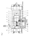
- the metal extrusion press shown in FIG. 1 consists of a cylinder spar 1, a counter spar 2 and anchors 3 connecting these.
- Guides 4 on the anchors 3 carry a running spar 5 which is guided by a plunger 7 guided and acted upon in the cylinder 6 of the cylinder spar 1 in the direction of the press axis is moved backwards in the pressing direction and by piston-cylinder units 8.
- the barrel 5 carries one Press ram 9.
- the guides 4 carry a spar 10 which is provided with a block receiver 11 and can be moved by piston-cylinder units 12 in the direction of the press axis.
- a die 14 is fastened to the counter beam 2 in a holder 13. To load a block to be pressed, the spar 10 is pushed with the block receiver 11 over the press ram 9, so that the space between the die 14 and a press disk 15 on the end face of the press ram 9 is exposed.
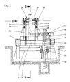
- the device for loading blocks consists of a bearing block 16 which rotatably carries a shaft 18 in two bearings 17, which shaft is formed between the bearings 17 as a square or spline shaft.
- the shaft 18 is pivoted in one direction or the other via the drive lever 19.
- swivel arm 24 and 25 On the shaft 18, two swivel arms 24 and 25 are attached in a rotationally fixed manner, the swivel arm 24 also being fastened axially to the shaft 18, while the swivel arm 25 is axially displaceably seated on the shaft 18 and by a piston-cylinder unit 26 which is in the drive lever 19 27 is supported, is moved axially.
- Each swivel arm 24 and 25 carries a charging cradle 28, 29.
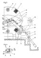
- the swivel arms 24 and 25 To accommodate a block 30, the swivel arms 24 and 25 are in the swivel position shown in dashed lines in FIG. 3, in which they take over the metal blocks 30, which are conveyed by an oven and heated to the pressing temperature.
- the swivel arms 24 and 25 are pivoted via the shaft 18 in such a way that the block 30 lying in their charging cradles 28 and 29 reaches the free tree between the die 14 and the pressure plate 15 in the press axis.
- the spar 10 with the block receiver 11 is moved towards the die 14 by means of the piston-cylinder units 12, the block receiver 11 being placed over the block 30.
- the swivel arm 25 is axially displaced on the shaft 18 by means of the piston-cylinder unit 26, up to the position shown in broken lines in FIG.
- the charging cradles 28 and 29 are fork-shaped and the charging cradle 28 consists of tines 31 and the charging cradle 29 consists of tines 32.
- the tines 31 are composed of yoke pieces 28a, 28b and the tines 32 are composed of yoke pieces 29a and 29b, the yoke piece 28a the end of the swivel arm 24 and the yoke piece 29a forms the end of the swivel arm 25, the yoke piece 28b is pivotable about an axis 33 in the swivel arm 25 and the yoke piece 29b about an axis 33.
- the yoke pieces 28b and 29b are each pivoted by a piston-cylinder unit 34 which are articulated on the pivot arms 24 and 25, respectively.
- the charging cradle 29 overlaps completely with the charging cradle 28 in the position of the swivel arm 25 shown in broken lines, which is due to the fork-like design of the charging cradles 28 and 29 with an offset arrangement of the tines 31 and 32, in which the tines 31 the charging cradle 28 face the gaps between the prongs 32 of the charging cradle 29 and vice versa.
- the piston-cylinder units 34 are acted upon jointly on both swivel arms 24 and 25, so that the yoke pieces 28b and 29b jointly swivel about their axes 33 into the position shown in broken lines in FIG. 3, so that the swivel arms 24 and 25 with the open arms Charging cradles 28 and 29 can be pivoted together past the block 30.
- a metal extrusion press in which a press disk 15 is used, which is firmly connected to the press ram 9, that is, it is not loaded with the block 30 for each pressing operation, as is common with light metal extrusion presses . If you want to work with a loose press disk 15, shorter blocks or longer charging cradles must be used to ensure that there is also space for the pressing disks on the charging cradles.
- the length of the charging cradles 28 and 29 is determined from the sufficient support for the blocks 30 to be loaded and the length of the blocks 30 determines the distance A between the charging cradles 28 and 29 in the starting position.
- more than two charging cradles can also be provided and designed according to the principle of the invention, as is shown in principle for three charging cradles in FIGS. 5 and 6.
- FIG. 5 shows the three charging cradles in an overlapping position
- FIG. 6 shows an opened position that has been moved apart.
- the swivel arms with the yoke pieces carrying the tines are denoted by 35, 36 and 37, the swivel arm 35 being a charging cradle 39 formed from prongs 38, the swiveling arm 36 being a charging cradle 41 formed from prongs 40 and the swivel arm 31 being a charging cradle 43 formed from prongs 42 wearing.
- the tines 38, 40, 42 are in turn offset from one another with the yoke pieces of the swivel arms 35, 36 and 37 so that a displacement of the swivel arms 36 and 37 according to arrows C and D leads to a complete overlap of the tines 38, 40 and 42.
Abstract
Description
Das Laden von Blöcken und gegebenenfalls von Preßscheiben in liegende Metallstrangpressen erfolgt mittels Vorrichtungen, bestehend aus mindestens einer Ladeschale, zumeist aber zwei oder auch mehr längs der Pressenachse hintereinander angeordneten Ladeschalen, die bzw. deren jede von einem Schwenkarm oder einem Schubstößel getragen in die Pressenachse einbringbar und wieder aus ihr ausbringbar ist. Das Laden kann zwischen dem Blockaufnehmer und dem Preßstempel erfolgen, wozu ein entsprechder Hubweg des Preßstempels erforderlich ist. ("Modernisierung einer 20-MN-Strangpressanlage für Aluminium" 64 (1988) Heft 4, S. 370/379). Zumeist wird jedoch der hierzu mit einer Verschiebevorrichtung versehene Blockaufnehmer der Strangpresse zunächst über den Preßstempel (DE-PS 519 038) oder bei für das indirekte Pressen eingerichteten Metallstrangpressen gegebenenfalls über den Matrizenstempel (DE-OS 30 29 234) verfahren, damit der Raum zwischen dem Preßwerkzeug und dem Preßstempel zugänglich ist. Nach dem Einbringen eines Blockes in die Pressenachse wird der Blockaufnehmer wieder zurückgefahren und nimmt den Block auf. Da es nicht immer möglich und oft nicht praktikabel ist, den Block und gegebenenfalls die Preßscheibe zwischen Preßwerkzeug und dem angedrückten Preßstempel einzuklemmen und in der Pressenachse zu halten (DE-AS 1 156 374), ist es üblich, zwei oder auch mehrere Ladeschalen in der Pressenachse hintereinander vorzusehen, die je nach Blocklänge einsetzbar sind (DE- AS 16 02 234) und auch nacheinander aus der Pressenachse ausbringbar sein können (DE- PS 1 021 820), wobei das Ausbringen einer Ladeschale erfolgt, so wie ein Block vom Blockaufnehmer aufgenommen wird und Stützung durch den Blockaufnehmer findet. Soweit hierbei der Blockaufnehmer verschoben wird, wird zumeist der Vorschub des Blockaufnehmers für die Zeit des Ausbringens einer Ladeschale unterbrochen, um eine Kollision von Blockaufnehmer und Ladeschale auszuschließen. Verschiedentlich wird auch die zum Blockaufnehmer hin gelegene Ladeschale gegenüber der anderen Ladeschale in Anlehnung an die Tragarme nach der DE- PS 519 038 verschiebbar angeordnet, wobei die eine oberflächenschonende Auflage der Blöcke bestimmende Breite der Ladeschalen den möglichen Raumgewinn begrenzt.Blocks and, if necessary, press disks are loaded into horizontal metal extrusion presses by means of devices consisting of at least one loading cradle, but usually two or more charging cradles arranged one behind the other along the press axis, each of which can be inserted into the press axis carried by a swivel arm or a push rod and can be brought out of it again. Loading can take place between the block receiver and the press ram, for which purpose a corresponding stroke of the press ram is required. ("Modernization of a 20 MN extrusion system for aluminum" 64 (1988)
Die Erfindung geht von den Vorrichtungen zum Laden von Blöcken und gegebenenfalls von Preßscheiben in liegende Metallstrangpressen aus, die zwei oder mehr längs der Pressenachse hintereinander angeordnete, von Schwenkarmen oder Schubstösseln getragene Ladeschalen aufweist, die in die Pressenachse einbringbar und wieder aus der Pressenachse ausbringbar sind und von denen zumindest die zweite Ladeschale und gegebenenfalls die weiteren Ladeschalen in Richtung der Pressenachse verschiebbar ist bzw. sind. Die Verschiebbarkeit einer Ladeschale gegen die andere setzt einen Abstand zwischen den Ladeschalen voraus, wobei die Breite der Ladeschalen zusammengenommen nicht mehr als die kleinste Blocklänge betragen darf. Der Abstand zwischen den Ladeschalen läßt aber ein Laden geteilter Blöcke nicht zu, deren Teilstücke die Lücke zwischen den Ladeschalen nicht ausreichend überbrücken. Soweit für das Ausbringen einer Ladeschale der Blockaufnehmer bei seinem Vorschub angehalten werden muß, ist der Zeitverlust ein weiterer Nachteil der bekannten Blocklader.The invention is based on the devices for loading blocks and, if appropriate, press disks into lying metal extrusion presses, which have two or more loading trays arranged one behind the other along the press axis and carried by swivel arms or push rods, which can be inserted into the press axis and can be removed again from the press axis, and of which at least the second charging cradle and optionally the further charging cradles can be displaced in the direction of the press axis. The displaceability of one charging cradle against the other presupposes a distance between the charging cradles, the width of the charging cradles taken together not being allowed to be more than the smallest block length. However, the distance between the charging cradles does not allow the loading of divided blocks, the sections of which do not bridge the gap between the charging cradles sufficiently. To the extent that the block pick-up has to be stopped when it is being advanced to deploy a charging cradle, the loss of time is a further disadvantage of the known block loaders.
Aufgabe der Erfindung ist es, mit Ladeschalen hinreichender Breite Blöcke unterschiedlicher Länge, geteilte Blöcke sowie Blöcke gemeinsam mit einer Preßscheibe sicher und ohne Unterbrechung laden zu können. Diese Aufgabe wird erfindungsgemäß dadurch gelöst, daß die Ladeschalen gabelartig mit gegeneinander versetzten Zinken und Lücken ausgebildet sind und jede Ladeschale mit ihren Zinken teleskopartig in die Lücke zwischen den Zinken der anderen Ladeschale bzw. Ladeschalen einfahrbar ist. Dadurch lassen sich die Ladeschalen auf eine Gesamtbreite zusammenfahren, die geringer als die Breite der einzelnen Ladeschalen zusammengenommen ist. Es erübrigt sich dadurch das Aus fahren einer Ladeschale und somit ein Anhalten des zum Laden verschiebbaren Bauteils der Presse, beispielsweise des Blockaufnehmers.The object of the invention is to be able to load blocks of different lengths, divided blocks and blocks together with a press disk safely and without interruption with charging trays of sufficient width. This object is achieved in that the charging cradles are fork-shaped with offset prongs and gaps and each charging cradle is telescopically retractable into the gap between the tines of the other charging cradle or charging cradles. As a result, the charging cradles can be moved together to a total width that is less than the width of the individual charging cradles combined. This eliminates the need to drive out a charging cradle and thus stop the component of the press that can be moved for loading, for example the block receiver.
Ein vollständiges Zusammenfahren der Ladeschalen auf die Breite einer einzigen Ladeschale wird dadurch erreicht, daß nach einem weiteren Merkmal der Erfindung die Zinken und die Lücken zwischen den Zinken der Ladeschalen sich über deren gesamte achsiale Breite erstrecken und die die Zinken zusammenfassenden nebeneinanderliegenden Joche außerhalb des Umkreises von Zinken und Lücken mit den ihnen zugeordneten Zinken entsprechend der Zuordnung versetzt verbunden sind, wobei die Breite der Joche zusammengenommen die achsiale Breite der Ladeschalen, die der Länge der Zinken entspricht, nicht übersteigt.A complete collapse of the charging cradles to the width of a single charging cradle is achieved in that after another Feature of the invention, the tines and the gaps between the tines of the charging cradles extend over their entire axial width and the adjacent yokes summarizing the tines are connected offset with the tines assigned to them outside the vicinity of tines and gaps, the width of the The yokes taken together do not exceed the axial width of the charging cradles, which corresponds to the length of the tines.
Ein Ausführungsbeispiel der Erfindung ist in den Zeichnungen dargestellt, die in
- Figur 1 die Gesamtansicht einer Metallstrangpresse mit der ihr zugeordneten Vorrichtung zum Laden von Blöcken und in
- Figur 2 als Ausschnitt in größerem Maßstab die Vorrichtung zum Laden von Blöcken zeigt,
Figur 3 zeigt die Vorrichtung und ausschnittsweise die Metallstrangpresse in Seitenansicht bzw. im Schnitt nach der in die Figuren 1 und 2 eingetragenen Linie III-III und inFigur 4 einen Ausschnitt gemäßFigur 3 in einer Ansicht in Richtung des Pfeils IV in Figur 2.
Ein weiteres Ausführungsbeispiel ist inFigur 5 undFigur 6 schematisch in zwei Betriebstellungen gezeigt.
- 1 shows the overall view of a metal extrusion press with the associated device for loading blocks and in
- FIG. 2 shows a detail of the device for loading blocks,
- FIG. 3 shows the device and a section of the metal extrusion press in a side view or in section along the line III-III and in FIG. 1 and 2
- FIG. 4 shows a detail according to FIG. 3 in a view in the direction of arrow IV in FIG. 2.
Another embodiment is in - Figure 5 and
- Figure 6 is shown schematically in two operating positions.
Die in Figur 1 dargestellte Metallstrangpresse besteht aus einem Zylinderholm 1, einem Gegenholm 2 und diese verbindenden Ankern 3. Führungen 4 an den Ankern 3 tragen einen Laufholm 5, der von einem im Zylinder 6 des Zylinderholms 1 geführten und beaufschlagten Plungerkolben 7 in Richtung der Pressenachse in Preßrichtung und von Kolben- Zylinder- Einheiten 8 rückwärts bewegt wird. Der Laufholm 5 trägt einen Preßstempel 9. Des weiteren tragen die Führungen 4 einen Holm 10 der mit einem Blockaufnehmer 11 versehen ist und von Kolben- Zylinder- Einheiten 12 in Richtung der Pressenachse bewegbar ist. Am Gegenholm 2 ist in einem Halter 13 eine Matrize 14 befestigt. Zum Laden eines zu verpressenden Blockes wird der Holm 10 mit dem Blockaufnehmer 11 über den Preßstempel 9 geschoben, so daß der Raum zwischen der Matrize 14 und einer Preßscheibe 15 an der Stirnseite des Preßstempels 9 frei liegt.The metal extrusion press shown in FIG. 1 consists of a cylinder spar 1, a counter spar 2 and
Die Vorrichtung zum Laden von Blöcken besteht aus einem Lagerblock 16, der in zwei Lagern 17 drehbar eine Welle 18 trägt, die zwischen den Lagern 17 als Vierkant- oder Keilwelle ausgebildet ist. Drehfest auf der Welle 18 sitzt ein Antriebshebel 19, an den die Kolbenstange 20 einer Kolben- Zylinder- Einheit 21 angreift, deren Zylinder 22 bei 23 im Lagerblock 16 schwenkbeweglich gelagert ist. Durch entsprechende Beaufschlagung des Kolbens der Kolben- Zylinder- Einheit 21 wird über den Antriebshebel 19 die Welle 18 in der einen oder anderen Richtung geschwenkt. Auf die Welle 18 sind drehfest zwei Schwenkarme 24 und 25 aufgesetzt, wobei der Schwenkarm 24 auch axial zur Welle 18 befestigt ist, während der Schwenkarm 25 axialverschiebbar auf der Welle 18 sitzt und durch eine Kolben- Zylinder- Einheit 26, die im Antriebshebel 19 bei 27 abgestützt ist, axial bewegt wird. Jeder Schwenkarm 24 und 25 trägt eine Ladeschale 28,29. Zur Aufnahme eines Blockes 30 befinden sich die Schwenkarme 24 und 25 in der in Figur 3 gestrichelt dargestellten Schwenkstellung, in der sie die von einem Ofen angeförderten, auf Preßtemperatur erhitzten Metallblöcke 30 übernehmen. Mittels der Kolben- Zylinder- Einheit 21 werden über die Welle 18 die Schwenkarme 24 und 25 so geschwenkt, daß der in ihren Ladeschalen 28 und 29 liegende Block 30 in die Pressenachse in den freien Baum zwischen der Matrize 14 und der Preßscheibe 15 gelangt. Nun wird mittels der Kolben- Zylinder- Einheiten 12 der Holm 10 mit dem Blockaufnehmer 11 auf die Matrize 14 zu verschoben, wobei der Blockaufnehmer 11 über den Block 30 gestülpt wird. Entsprechend dem Vorschub des Blockaufnehmers 11 wird mittels der Kolben- Zylinder- Einheit 26 der Schwenkarm 25 axial auf der Welle 18 verschoben, bis in die in Figur 2 gestrichelt gezeichnete Stellung.The device for loading blocks consists of a
Die Ladeschalen 28 und 29 sind gabelartig ausgebildet und es besteht die Ladeschale 28 aus Zinken 31 und die Ladeschale 29 aus Zinken 32. Die Zinken 31 sind von Jochstücken 28a, 28b und die Zinken 32 sind von Jochstücken 29a und 29b zusammengefaßt, wobei das Jochstück 28a das Ende des Schwenkarmes 24 und das Jochstück 29a das Ende des Schwenkarmes 25 bildet, das Jochstück 28b in eine Achse 33 im Schwenkarm 24 und das Jochstück 29b um eine Achse 33 im Schwenkarm 25 schwenkbär ist. Geschwenkt werden die Jochstücke 28b und 29b von je einer Kolben- Zylinder- Einheit 34 die an die Schwenkarme 24 bzw. 25 angelenkt sind. Wie die Figur 2 erkennen läßt, überschneidet sich die Ladeschale 29 in der gestrichelt dargestellten Stellung des Schwenkarmes 25 völlig mit der Ladeschale 28, was durch die gabelartige Ausbildung der Ladeschalen 28 und 29 bei versetzter Anordnung der Zinken 31 und 32, bei der die Zinken 31 der Ladeschale 28 den Lücken zwischen den Zinken 32 der Ladeschale 29 und umgekehrt gegenüberstehen, erreicht ist. Ein vorzeitiges Ausschwenken des Schwenkarmes 25 mit seiner Ladeschale 29, wie es nach dem Stand der Technik nötig ist, wenn sich die Ladeschale 29 der Ladeschale 28 genähert hat und die Ladeschale 28 noch zur Stützung des zu ladenden Blocks 30, eines Blockabschnitts oder einer Preßscheibe benötigt wird, kann somit entfallen und es können die Ladeschalen 28 und 29 in gegenseitiger Überschneidung gemeinsam ausgeschwenkt werden. Hierzu werden die Kolben- Zylinder- Einheiten 34 an beiden Schwenkarmen 24 und 25 gemeinsam beaufschlagt, so daß die Jochstücke 28b und 29b gemeinsam um ihre Achsen 33 schwenken in die in Figur 3 gestrichelt gezeichnete Stellung, so daß die Schwenkarme 24 und 25 mit den geöffneten Ladeschalen 28 und 29 an dem Block 30 vorbei gemeinsam ausgeschwenkt werden können.The
In dem Ausführungsbeispiel nach Figur 1 ist eine Metallstrangpresse dargestellt, bei der mit einer Preßscheibe 15 gearbeitet wird, die fest mit dem Preßstempel 9 verbunden ist, also nicht mit dem Block 30 zu jedem Preßvorgang geladen wird, wie dies bei Leichtmetall- Strangpressen verbreitet üblich ist. Falls mit loser Preßscheibe 15 gearbeitet werden soll, muß durch kürzere Blöcke oder längere Ladeschalen dafür gesorgt werden, daß auch die Preßscheiben auf den Ladeschalen Platz finden.In the exemplary embodiment according to FIG. 1, a metal extrusion press is shown, in which a
Die Länge der Ladeschalen 28 und 29 bestimmt sich aus der ausreichenden Auflage für die zu ladenden Blöcke 30 und die Länge der Blöcke 30 bestimmt den Abstand A zwischen den Ladeschalen 28 und 29 in der Ausgangsstellung. Um trotz großer Ladelänge mit kurzen Ladeschalen und geringen oder ohne Abstand zwischen den Ladeschalen auszukommen, können nach dem Prinzip der Erfindung auch mehr als zwei Ladeschalen vorgesehen und ausgebildet sein, wie dies im Prinzip für drei Ladeschalen in den Figuren 5 und 6 dargestellt ist. Hierbei zeigt die Figur 5 die drei Ladeschalen in sich überschneidener Stellung und die Figur 6 auseinandergefahrener geöffneter Stellung. Die Schwenkarme mit den die Zinken tragenden Jochstücke sind mit 35, 36 und 37 bezeichnet, wobei der Schwenkarm 35 eine aus Zinken 38 gebildete Ladeschale 39, der Schwenkarm 36 eine aus Zinken 40 gebildete Ladeschale 41 und der Schwenkarm 31 eine aus Zinken 42 gebildete Ladeschale 43 trägt. Die Zinken 38, 40, 42 sind wiederum so gegeneinander versetzt mit den Jochstücken der Schwenkarme 35, 36 und 37 verbunden, daß eine Verschiebung der Schwenkarme 36 und 37 gemäß den Pfeilen C und D zur völligen Überschneidung der Zinken 38,40 und 42 führt.The length of the
Claims (2)
dadurch gekennzeichnet,
daß die Ladeschalen (28,29;39,41,43) gabelartig mit gegeneinander versetzten Zinken (31,32;38,40,42) und Lücken ausgebildet sind und jede Ladeschale (29;41,43) mit ihren Zinken (32;40,42) teleskopartig in die Lücken zwischen den Zinken (31;38) der anderen Ladeschale (28) bzw. Ladeschalen (41,43) einfahrbar ist.1.Device for loading blocks and, if necessary, pressing disks into lying metal extrusion presses, with two or more consecutively arranged along the press axis, carried by swivel arms or push rams, which can be inserted into the press axis between the press tool or press ram and block receiver, and can be removed again from it, at least of which the second charging cradle and, if appropriate, further charging cradles can be moved in the direction of the press axis,
characterized,
that the charging cradles (28, 29; 39, 41, 43) are fork-shaped with prongs (31, 32; 38, 40, 42) offset from one another and gaps, and each charging cradle (29; 41, 43) with its prongs (32; 40, 42) can be telescoped into the gaps between the tines (31; 38) of the other charging cradle (28) or charging cradles (41, 43).
dadurch gekennzeichnet,
daß die Zinken (31,32;38,40,42) und die Lücken zwischen den Zinken (31,32;38,40,42) sich über die gesamte axiale Länge einer jeden Ladeschale (28,29;39,41,43) erstrecken, die die Zinken (31,32;38,40,42) zusammenfassenden nebeneinanderliegenden Joche (28a,28b,29a,29b) bzw. Schwenkarme (24,25;35,36,37) außerhalb des Umkreises von Zinken (31,32;38,40,42) und Lücken mit den ihnen zugeordneten Zinken (31 zu 24,28a,28b, 32 zu 25,29a,29b; 38 zu 35, 40 zu 36, 42 zu 37) entsprechend der Zuordnung versetzt verbunden sind und die Breite der Joche (28a,28b,29a,29b) bzw. Schwenkarme (24,25;35,36,37) zusammengenommen geringer als die axiale Länge der Zinken (31,32;38,40,42) bemessen ist.2. Loading device according to claim 1,
characterized,
that the tines (31.32; 38.40.42) and the gaps between the tines (31.32; 38.40.42) extend over the entire axial length of each charging cradle (28.29; 39.41.43 ) extend the yokes (28a, 28b, 29a, 29b) or swivel arms (24,25; 35,36,37) which join the adjacent tines (31,32; 38,40,42) outside the circumference of tines (31 , 32; 38,40,42) and gaps with the associated tines (31 to 24,28a, 28b, 32 to 25,29a, 29b; 38 to 35, 40 to 36, 42 to 37) offset according to the assignment and the width of the yokes (28a, 28b, 29a, 29b) or swivel arms (24.25; 35.36.37) taken together is smaller than the axial length of the tines (31.32; 38.40.42) .
Applications Claiming Priority (2)
| Application Number | Priority Date | Filing Date | Title |
|---|---|---|---|
| DE3938790A DE3938790C1 (en) | 1989-11-23 | 1989-11-23 | |
| DE3938790 | 1989-11-23 |
Publications (3)
| Publication Number | Publication Date |
|---|---|
| EP0428989A2 true EP0428989A2 (en) | 1991-05-29 |
| EP0428989A3 EP0428989A3 (en) | 1991-12-27 |
| EP0428989B1 EP0428989B1 (en) | 1994-07-13 |
Family
ID=6394033
Family Applications (1)
| Application Number | Title | Priority Date | Filing Date |
|---|---|---|---|
| EP90121768A Expired - Lifetime EP0428989B1 (en) | 1989-11-23 | 1990-11-14 | Apparatus for loading billets and eventually pressing discs in horizontal metal extrusion presses |
Country Status (2)
| Country | Link |
|---|---|
| EP (1) | EP0428989B1 (en) |
| DE (2) | DE3938790C1 (en) |
Cited By (5)
| Publication number | Priority date | Publication date | Assignee | Title |
|---|---|---|---|---|
| EP0791413A1 (en) * | 1996-02-26 | 1997-08-27 | Sms Schloemann Gmbh | Apparatus for loading billets and optionally pressing discs in a horizontal metal-extrusion press |
| WO2004000538A2 (en) * | 2002-06-19 | 2003-12-31 | Sms Eumuco Gmbh | Extruding and pipe press |
| WO2004076088A1 (en) * | 2003-02-27 | 2004-09-10 | Danieli & C. Officine Meccaniche S.P.A. | Billet loader for extrusion presses |
| WO2005110636A1 (en) * | 2004-05-10 | 2005-11-24 | Sms Eumuco Gmbh | Extruding press for billets and tubes |
| CN107639126A (en) * | 2017-11-09 | 2018-01-30 | 江苏启力锻压机床有限公司 | Horizontal bimodulus cold extruding mechanism and shaping production technology |
Families Citing this family (1)
| Publication number | Priority date | Publication date | Assignee | Title |
|---|---|---|---|---|
| EP0574592B1 (en) * | 1992-04-15 | 1994-03-16 | SMS Hasenclever GmbH | Apparatus for loading billets and eventually pressing discs in horizontal metal extrusion presses |
Citations (3)
| Publication number | Priority date | Publication date | Assignee | Title |
|---|---|---|---|---|
| DE519038C (en) * | 1929-02-05 | 1931-02-23 | Fried Krupp Grusonwerk Akt Ges | Horizontal extrusion press with movable billet support device |
| DE1602234B2 (en) * | 1966-06-29 | 1978-09-21 | Wean United, Inc., Pittsburgh, Pa. (V.St.A.) | Device on a horizontal metal extruder for holding the press block |
| JPS54136560A (en) * | 1978-04-14 | 1979-10-23 | Ube Ind Ltd | Billet loader for extrusion press |
Family Cites Families (2)
| Publication number | Priority date | Publication date | Assignee | Title |
|---|---|---|---|---|
| DE1156374B (en) * | 1959-09-25 | 1963-10-31 | Hydraulik Gmbh | Block holding device for horizontal metal extrusion press |
| DE3029234A1 (en) * | 1980-08-01 | 1982-04-01 | Schloemann-Siemag AG, 4000 Düsseldorf | Indirect extrusion press - where billet residue can be sheared off extruder barrel plug without displacing extrusion tools (BR 29.9.81) |
-
1989
- 1989-11-23 DE DE3938790A patent/DE3938790C1/de not_active Expired - Lifetime
-
1990
- 1990-11-14 EP EP90121768A patent/EP0428989B1/en not_active Expired - Lifetime
- 1990-11-14 DE DE59006422T patent/DE59006422D1/en not_active Expired - Lifetime
Patent Citations (3)
| Publication number | Priority date | Publication date | Assignee | Title |
|---|---|---|---|---|
| DE519038C (en) * | 1929-02-05 | 1931-02-23 | Fried Krupp Grusonwerk Akt Ges | Horizontal extrusion press with movable billet support device |
| DE1602234B2 (en) * | 1966-06-29 | 1978-09-21 | Wean United, Inc., Pittsburgh, Pa. (V.St.A.) | Device on a horizontal metal extruder for holding the press block |
| JPS54136560A (en) * | 1978-04-14 | 1979-10-23 | Ube Ind Ltd | Billet loader for extrusion press |
Non-Patent Citations (1)
| Title |
|---|
| PATENT ABSTRACTS OF JAPAN vol. 4, no. 2 (C-69)9. Januar 1980 & JP-A-54 136 560 ( UBE KOSAN KK ) 23. Oktober 1979 * |
Cited By (12)
| Publication number | Priority date | Publication date | Assignee | Title |
|---|---|---|---|---|
| EP0791413A1 (en) * | 1996-02-26 | 1997-08-27 | Sms Schloemann Gmbh | Apparatus for loading billets and optionally pressing discs in a horizontal metal-extrusion press |
| US5823038A (en) * | 1996-02-26 | 1998-10-20 | Sms Eumuco Gmbh | Apparatus for loading a billet and, if necessary, a pressing disc into a horizontal metal extrusion press |
| WO2004000538A2 (en) * | 2002-06-19 | 2003-12-31 | Sms Eumuco Gmbh | Extruding and pipe press |
| DE10227488B3 (en) * | 2002-06-19 | 2004-02-12 | Sms Eumuco Gmbh | Extrusion and tube press |
| WO2004000538A3 (en) * | 2002-06-19 | 2004-02-26 | Sms Eumuco Gmbh | Extruding and pipe press |
| US7216522B2 (en) | 2002-06-19 | 2007-05-15 | Sms Eumuco Gmbh | Extruding and pipe press |
| WO2004076088A1 (en) * | 2003-02-27 | 2004-09-10 | Danieli & C. Officine Meccaniche S.P.A. | Billet loader for extrusion presses |
| CN1326641C (en) * | 2003-02-27 | 2007-07-18 | 达涅利机械工业有限公司 | Billet loader for extrusion presses |
| US7357383B2 (en) | 2003-02-27 | 2008-04-15 | Danieli & C. Officine Meccaniche S.P.A. | Billet loader for extrusion presses |
| WO2005110636A1 (en) * | 2004-05-10 | 2005-11-24 | Sms Eumuco Gmbh | Extruding press for billets and tubes |
| US7448245B2 (en) | 2004-05-10 | 2008-11-11 | Sms Eumuco Gmbh | Extruding press for billets and tubes |
| CN107639126A (en) * | 2017-11-09 | 2018-01-30 | 江苏启力锻压机床有限公司 | Horizontal bimodulus cold extruding mechanism and shaping production technology |
Also Published As
| Publication number | Publication date |
|---|---|
| DE3938790C1 (en) | 1990-12-06 |
| EP0428989B1 (en) | 1994-07-13 |
| DE59006422D1 (en) | 1994-08-18 |
| EP0428989A3 (en) | 1991-12-27 |
Similar Documents
| Publication | Publication Date | Title |
|---|---|---|
| DE3423283C2 (en) | ||
| DE2044183B2 (en) | Punching machine | |
| DE2166983B2 (en) | Surgical instrument for laying around staples to tie off tubular organic structures | |
| DE1777105A1 (en) | Device for loading a processing machine with workpieces | |
| DE19643163A1 (en) | Tool changing device for a forming press and forming press tool changing device arrangement | |
| DE3404553C2 (en) | Handling device, in particular for loading and unloading machine tools | |
| DE3938790C1 (en) | ||
| DE2411744A1 (en) | PRESS FOR PRESSING CONNECTING AT LEAST PARTIALLY WIRE-SHAPED PART WITH A TERMINAL PART | |
| DE19724635C2 (en) | Machine tool with tool changing device | |
| EP3778049B1 (en) | Processing machine for flat material parts with a laying unit and method therefor | |
| DE7737111U1 (en) | DEVICE FOR LOADING MACHINE TOOLS, IN PARTICULAR LATHE | |
| DE10223897A1 (en) | Tool changing device for presses | |
| EP0574592B1 (en) | Apparatus for loading billets and eventually pressing discs in horizontal metal extrusion presses | |
| DE3315569A1 (en) | METHOD AND MACHINE FOR MANIPULATING RODS | |
| DE3312557C2 (en) | ||
| DE102009007151B4 (en) | Deburring press with a device for removing a deburred workpiece, removal device for this trimming press and method for removing a deburred workpiece from this trimming press | |
| DE2843531A1 (en) | MACHINE FOR THE PRODUCTION OF REINFORCEMENT FROM METAL IN PARTICULAR FOR REINFORCED CONCRETE | |
| DE3508354C2 (en) | Machine for squeezing cable wire ends with wire end sleeves or the like. Connecting elements | |
| DE3401422C2 (en) | ||
| EP0243787B1 (en) | Transport system for circulation of dummy blocks and matrizes on extruding presses arranged for direct and indirect extruding | |
| DE2856007C2 (en) | Profiling machine or the like. with interchangeable roller tools arranged in pairs in bearing brackets | |
| DE2229738C3 (en) | Indirect extrusion press | |
| EP0332839A1 (en) | Automatically charged screw driver | |
| EP0675771B1 (en) | Working method for loading a billet into a metal extrusion press | |
| DE3204648C2 (en) | Clamping device for clamping sheet metal plates in a stretch leveler |
Legal Events
| Date | Code | Title | Description |
|---|---|---|---|
| PUAI | Public reference made under article 153(3) epc to a published international application that has entered the european phase |
Free format text: ORIGINAL CODE: 0009012 |
|
| 17P | Request for examination filed |
Effective date: 19901114 |
|
| AK | Designated contracting states |
Kind code of ref document: A2 Designated state(s): DE FR GB IT |
|
| PUAL | Search report despatched |
Free format text: ORIGINAL CODE: 0009013 |
|
| AK | Designated contracting states |
Kind code of ref document: A3 Designated state(s): DE FR GB IT |
|
| 17Q | First examination report despatched |
Effective date: 19930222 |
|
| ITF | It: translation for a ep patent filed |
Owner name: DE DOMINICIS & MAYER S.R.L. |
|
| GRAA | (expected) grant |
Free format text: ORIGINAL CODE: 0009210 |
|
| AK | Designated contracting states |
Kind code of ref document: B1 Designated state(s): DE FR GB IT |
|
| REF | Corresponds to: |
Ref document number: 59006422 Country of ref document: DE Date of ref document: 19940818 |
|
| GBT | Gb: translation of ep patent filed (gb section 77(6)(a)/1977) |
Effective date: 19940727 |
|
| ET | Fr: translation filed | ||
| PLBE | No opposition filed within time limit |
Free format text: ORIGINAL CODE: 0009261 |
|
| STAA | Information on the status of an ep patent application or granted ep patent |
Free format text: STATUS: NO OPPOSITION FILED WITHIN TIME LIMIT |
|
| 26N | No opposition filed | ||
| PGFP | Annual fee paid to national office [announced via postgrant information from national office to epo] |
Ref country code: GB Payment date: 20011012 Year of fee payment: 12 |
|
| REG | Reference to a national code |
Ref country code: GB Ref legal event code: IF02 |
|
| PG25 | Lapsed in a contracting state [announced via postgrant information from national office to epo] |
Ref country code: GB Free format text: LAPSE BECAUSE OF NON-PAYMENT OF DUE FEES Effective date: 20021114 |
|
| GBPC | Gb: european patent ceased through non-payment of renewal fee | ||
| PGFP | Annual fee paid to national office [announced via postgrant information from national office to epo] |
Ref country code: DE Payment date: 20091120 Year of fee payment: 20 |
|
| PGFP | Annual fee paid to national office [announced via postgrant information from national office to epo] |
Ref country code: FR Payment date: 20091201 Year of fee payment: 20 Ref country code: IT Payment date: 20091126 Year of fee payment: 20 |
|
| PG25 | Lapsed in a contracting state [announced via postgrant information from national office to epo] |
Ref country code: DE Free format text: LAPSE BECAUSE OF EXPIRATION OF PROTECTION Effective date: 20101114 |