EP0428610B1 - Cutting using high energy radiation - Google Patents
Cutting using high energy radiation Download PDFInfo
- Publication number
- EP0428610B1 EP0428610B1 EP89909590A EP89909590A EP0428610B1 EP 0428610 B1 EP0428610 B1 EP 0428610B1 EP 89909590 A EP89909590 A EP 89909590A EP 89909590 A EP89909590 A EP 89909590A EP 0428610 B1 EP0428610 B1 EP 0428610B1
- Authority
- EP
- European Patent Office
- Prior art keywords
- cut
- radiation
- incident radiation
- axis
- lens
- Prior art date
- Legal status (The legal status is an assumption and is not a legal conclusion. Google has not performed a legal analysis and makes no representation as to the accuracy of the status listed.)
- Expired - Lifetime
Links
- 230000005855 radiation Effects 0.000 title claims abstract description 36
- 238000005520 cutting process Methods 0.000 title description 7
- 238000000034 method Methods 0.000 claims description 10
- 230000008859 change Effects 0.000 claims description 3
- 238000004519 manufacturing process Methods 0.000 claims description 2
- 239000010432 diamond Substances 0.000 abstract description 16
- 229910003460 diamond Inorganic materials 0.000 abstract description 15
- 239000010437 gem Substances 0.000 description 6
- 230000008901 benefit Effects 0.000 description 5
- 229910001751 gemstone Inorganic materials 0.000 description 5
- 239000004575 stone Substances 0.000 description 3
- 238000009826 distribution Methods 0.000 description 2
- 239000000463 material Substances 0.000 description 2
- 230000009286 beneficial effect Effects 0.000 description 1
- 230000008878 coupling Effects 0.000 description 1
- 238000010168 coupling process Methods 0.000 description 1
- 238000005859 coupling reaction Methods 0.000 description 1
- 238000010586 diagram Methods 0.000 description 1
- 230000000694 effects Effects 0.000 description 1
- 239000011521 glass Substances 0.000 description 1
- 238000003698 laser cutting Methods 0.000 description 1
- 230000007246 mechanism Effects 0.000 description 1
- 239000002184 metal Substances 0.000 description 1
- 230000003287 optical effect Effects 0.000 description 1
- 239000010453 quartz Substances 0.000 description 1
- VYPSYNLAJGMNEJ-UHFFFAOYSA-N silicon dioxide Inorganic materials O=[Si]=O VYPSYNLAJGMNEJ-UHFFFAOYSA-N 0.000 description 1
- 230000008646 thermal stress Effects 0.000 description 1
- 239000012780 transparent material Substances 0.000 description 1
- 230000004580 weight loss Effects 0.000 description 1
- 238000003466 welding Methods 0.000 description 1
Images

Classifications
-
- B—PERFORMING OPERATIONS; TRANSPORTING
- B23—MACHINE TOOLS; METAL-WORKING NOT OTHERWISE PROVIDED FOR
- B23K—SOLDERING OR UNSOLDERING; WELDING; CLADDING OR PLATING BY SOLDERING OR WELDING; CUTTING BY APPLYING HEAT LOCALLY, e.g. FLAME CUTTING; WORKING BY LASER BEAM
- B23K26/00—Working by laser beam, e.g. welding, cutting or boring
- B23K26/36—Removing material
- B23K26/362—Laser etching
- B23K26/364—Laser etching for making a groove or trench, e.g. for scribing a break initiation groove
Definitions
- the present application relates to a method of and apparatus for making a cut using high energy radiation according to the preamble of claim 1 and 6 (see DE-A-1 752 846), the radiation usually being a laser beam.
- a blind groove or hole may be formed in the workpiece, or the workpiece may be cut or pierced right through.
- the invention has general applicability and in general terms, unnecessary material removal must be avoided as this slows down the cutting process; however, the invention is particularly applicable to gemstones, where it is specially important to avoid unnecessary material removal, and it is also necessary to avoid applying excessive thermal stress; in addition, a particular problem with gemstones such as diamond is that usually only a small percentage of the radiation may be absorbed, so it is important that the coupling of the energy to the workpiece be as effective as possible.
- US 4 644 126 discloses a device for welding metal parts together using an oscillating beam of high energy radiation.
- DE-A-1 752 846 discloses a device for cutting a generally conical bore in a diamond using a beam of high energy radiation.
- the laser cutting can be referred to as forming a kerf (a groove, either for cleaving or for later sawing), or sawing (cutting right through).
- a blind hole or a through-hole may be formed in order to employ the stone as a bearing.
- a fundamental problem is that the energy density in the focal spot should be as great as possible, but a smaller focal spot (and thus higher energy density) can only be obtained by increasing the cone angle of the focussed beam (i.e. high numerical aperture).
- the machined V-section has then to be wider, otherwide the laser energy focussed into the cut is apertured (vignetted) at the entrance to the cut as the depth increases.
- the present invention provides a method of making a cut using high energy radiation, the axis of the incident radiation relative to the cut being moved repeatedly from a position in which it is directed towards a first side of the cut and is inclined towards the other, second side of the cut to a position in which it is directed towards the second side of the cut and is inclined towards the first side of the cut and back again, characterised in that the incident radiation is focussed substantially on the base of the cut and the focus is altered as the cut deepens to keep the incident radiation focussed substantially on the base of the cut.
- the invention further provides an apparatus for making a cut using high energy radiation, the apparatus comprising means for moving the axis of incident radiation relative to the cut from a position in which it is directed towards a first side of the cut and is inclined towards the other, second side of the cut to a position in which it is directed towards the second side of the cut and is inclined towards the first side of the cut, and back again, characterised in that means are provided for focussing the incident radiation substantially on the base of the cut and for automatically altering the focus as the cut deepens to keep the incident radiation focussed substantially on the base of the cut.
- the most intense part of the beam can be centred over the cut opening, reducing the effect of vignetting upon energy entering the cut by oscillating the beam.
- the angle between the incident radiation and the side wall of the cut is increased, thereby reducing the size of the focal spot projected onto the side wall, and consequently increasing the energy density.
- the technique is applicable for most laser types; although currently the preferred system for diamonds uses infra-red radiation of 1.064nm from a Q-switched, neodymium-doped YAG laser, it is possible that frequency doubled YAG (532nm), frequently quadrupled YAG (266nm) and even shorter wavelength lasers such as ArF and KrF excimer lasers (193nm and 248nm wavelengths respectively) can be used.
- the technique is theoretically most beneficial with a Gaussian beam; in practice an advantage may be achieved using a near-Gaussian beam.
- One suitable system has a 10 mm expanded beam diameter and a focussing lens with a focal length of 50 mm.
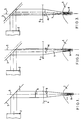
- Figures 1 to 3 schematically show a diamond 1 which is being sawn using a laser with a beam expander 2, the optical system including a 45° mirror 3 and a focussing or objective lens 4.
- the diamond 1 is always machined on the optic axis 5 of the focussing lens 4, at the focal point.
- the double arrows in Figure 1 indicate the movement of the mirror 3 and of the diamond 1, whilst the dashed lines in Figures 2 and 3 indicate the centre positions of the mirror 3 and diamond 1 (i.e. as in Figure 1).
- the diamond 1 is moved from side to side and the mirror 3 is translated so that the laser radiation entering the rear of the lens 4 is displaced in the same direction as the diamond 1.
- the mirror 3 must be large enough to provide a reflective surface to the incident beam at all times.
- the lens 4 is held stationary and although the incident beam is still parallel to the optic axis 5 of the lens 4, the axis of the beam above the lens 4 is displaced from the centre of the lens 4 (see the double arrow 6 in Figure 1). In this way the axis 7 of the incident beam below the lens 5, is oscillated or 'rocked' about the focal point (see the double arrow 8 in Figure 1), but the effective position of the focal point does not change.
- An advantage of this method of beam rocking is that there is no need to displace the diamond 1 in order to compensate for the fact that the beam is being rocked because the laser radiation is focussed to nominally the same position. However, the diamond 1 is moved to and fro transversely for benching out the cut.
- the axis 5 is thus moved repeatedly from a position in which it is directed towards the left side of the cut 9 and is inclined towards the right side of the cut 9, to a position in which it is directed towards the right side of the cut 9 and is inclined towards the left side of the cut 9, and back again.
- the angle 2 ⁇ through which the axis 7 is rocked will depend on the desired inclination of the cut side walls, the instantaneous cut depth, the size of the stone 1 being sawn, and the geometry of the focussed beam, but is preferably an included angle of 10°.
- the stroke of the mirror 3 will depend upon the desired rocking angle and focal lens of the lens 4, but may be typically 5mm.
- the rocking half angle ⁇ is shown as less than the half angle of the cone of rays, but it could be equal to or greater than the cone half angle.
- the beam entering the rear of the lens 4 can be displaced by rotating a parallel-sided block of transparent material (e.g. glass or quartz) in the radiation between the laser and the lens 4.
- Other beam rocking methods involve displacing or rotating the mirror 3 and/or focussing lens 4 and, where necessary, displacing the stone 1 to compensate for any change in focal spot position; e,g. the mirror 3 can be reciprocated vertically, or in any suitable direction.
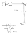
- Figure 4 shows a laser 11, which can be a high power Q-switched YAG laser in fundamental TEM oo mode, which produces a beam having a Gaussian energy distribution and a very small focal spot.
- Other components are generally as illustrated in Figures 1-3, but the automatic positioning mechanism or "work-handling" 12 is shown, the diamond 1 (not shown) being mounted on the work-handling 12.
- the work-handling 12 can move the diamond 1 along x and y axes for benching out, and the lens 4 is movable along the z axis for focussing. These movements are carried out automatically in a known manner.
- the mirror 3 is in this case representated as being moveable in a vertical direction.
- Figure 5 a illustrates the vignetting which occurs with the invention
- Figure 5 b gives the corresponding energy distribution graph, the shaded portions representating energy which is not available for cutting (the energy is the area under the graph).
- Figure 5 c illustrates the corresponding graph when the side of the cut is machined without rocking or swinging in accordance with the invention.
- Figure 6 a illustrates that the invention increases the angle between the incident beam 21 and the side wall 22 of the cut, and thus reduces the projected size of the focal spot and increases the energy density.
- Figure 6 b illustrates the same situation without swinging or rocking.
Landscapes
- Physics & Mathematics (AREA)
- Optics & Photonics (AREA)
- Engineering & Computer Science (AREA)
- Plasma & Fusion (AREA)
- Mechanical Engineering (AREA)
- Laser Beam Processing (AREA)
- Processing Of Stones Or Stones Resemblance Materials (AREA)
Abstract
Description
- The present application relates to a method of and apparatus for making a cut using high energy radiation according to the preamble of claim 1 and 6 (see DE-A-1 752 846), the radiation usually being a laser beam. A blind groove or hole may be formed in the workpiece, or the workpiece may be cut or pierced right through. The invention has general applicability and in general terms, unnecessary material removal must be avoided as this slows down the cutting process; however, the invention is particularly applicable to gemstones, where it is specially important to avoid unnecessary material removal, and it is also necessary to avoid applying excessive thermal stress; in addition, a particular problem with gemstones such as diamond is that usually only a small percentage of the radiation may be absorbed, so it is important that the coupling of the energy to the workpiece be as effective as possible.
- US 4 644 126 discloses a device for welding metal parts together using an oscillating beam of high energy radiation. DE-A-1 752 846 discloses a device for cutting a generally conical bore in a diamond using a beam of high energy radiation.
- In gemstones, the laser cutting can be referred to as forming a kerf (a groove, either for cleaving or for later sawing), or sawing (cutting right through). In other applications using Jewels or gemstones, a blind hole or a through-hole may be formed in order to employ the stone as a bearing.
- When sawing gemstones, normal practice is to form a V-section, which should be as narrow as possible to reduce weight loss. There is automatic machinery for benching out the V-shape (i.e. scanning the area formed by the length and width of the cut) and for refocussing the beam as the cut depth increases.
- A fundamental problem is that the energy density in the focal spot should be as great as possible, but a smaller focal spot (and thus higher energy density) can only be obtained by increasing the cone angle of the focussed beam (i.e. high numerical aperture). The machined V-section has then to be wider, otherwide the laser energy focussed into the cut is apertured (vignetted) at the entrance to the cut as the depth increases.
- The present invention provides a method of making a cut using high energy radiation, the axis of the incident radiation relative to the cut being moved repeatedly from a position in which it is directed towards a first side of the cut and is inclined towards the other, second side of the cut to a position in which it is directed towards the second side of the cut and is inclined towards the first side of the cut and back again, characterised in that the incident radiation is focussed substantially on the base of the cut and the focus is altered as the cut deepens to keep the incident radiation focussed substantially on the base of the cut.
- The invention further provides an apparatus for making a cut using high energy radiation, the apparatus comprising means for moving the axis of incident radiation relative to the cut from a position in which it is directed towards a first side of the cut and is inclined towards the other, second side of the cut to a position in which it is directed towards the second side of the cut and is inclined towards the first side of the cut, and back again, characterised in that means are provided for focussing the incident radiation substantially on the base of the cut and for automatically altering the focus as the cut deepens to keep the incident radiation focussed substantially on the base of the cut.
- Preferred and/or optional features of the invention are set forth in
Claims 2 to 5, 7 and 8. - The most intense part of the beam can be centred over the cut opening, reducing the effect of vignetting upon energy entering the cut by oscillating the beam.
- In addition, the angle between the incident radiation and the side wall of the cut is increased, thereby reducing the size of the focal spot projected onto the side wall, and consequently increasing the energy density.
- The technique is applicable for most laser types; although currently the preferred system for diamonds uses infra-red radiation of 1.064nm from a Q-switched, neodymium-doped YAG laser, it is possible that frequency doubled YAG (532nm), frequently quadrupled YAG (266nm) and even shorter wavelength lasers such as ArF and KrF excimer lasers (193nm and 248nm wavelengths respectively) can be used. The technique is theoretically most beneficial with a Gaussian beam; in practice an advantage may be achieved using a near-Gaussian beam. One suitable system has a 10 mm expanded beam diameter and a focussing lens with a focal length of 50 mm.
- Significant advantages can be obtained if the invention described herein is combined with the invention described in a patent application filed in August 1989 and entitled "Making an elongate cut using high energy radiation" and claiming priority from GB 88 19351.
- The invention will be further described, by way of example, with reference to the accompanying drawings, in which:-
- Figures 1 to 3 are three schematic views along the cut, illustrating the principle, and showing the beam below the lens respectively centered, cutting the right hand wall and cutting the left hand wall;
- Figure 4 is a schematic diagram of a practical embodiment;
- Figures 5a, 5b and 5c illustrate an advantage of the invention; and
- Figures 6a and 6b illustrate another advantage of the invention.
- Figures 1 to 3 schematically show a diamond 1 which is being sawn using a laser with a beam expander 2, the optical system including a 45°
mirror 3 and a focussing or objective lens 4. The diamond 1 is always machined on the optic axis 5 of the focussing lens 4, at the focal point. The double arrows in Figure 1 indicate the movement of themirror 3 and of the diamond 1, whilst the dashed lines in Figures 2 and 3 indicate the centre positions of themirror 3 and diamond 1 (i.e. as in Figure 1). The diamond 1 is moved from side to side and themirror 3 is translated so that the laser radiation entering the rear of the lens 4 is displaced in the same direction as the diamond 1. Themirror 3 must be large enough to provide a reflective surface to the incident beam at all times. The lens 4 is held stationary and although the incident beam is still parallel to the optic axis 5 of the lens 4, the axis of the beam above the lens 4 is displaced from the centre of the lens 4 (see the double arrow 6 in Figure 1). In this way the axis 7 of the incident beam below the lens 5, is oscillated or 'rocked' about the focal point (see the double arrow 8 in Figure 1), but the effective position of the focal point does not change. An advantage of this method of beam rocking is that there is no need to displace the diamond 1 in order to compensate for the fact that the beam is being rocked because the laser radiation is focussed to nominally the same position. However, the diamond 1 is moved to and fro transversely for benching out the cut. - The axis 5 is thus moved repeatedly from a position in which it is directed towards the left side of the
cut 9 and is inclined towards the right side of thecut 9, to a position in which it is directed towards the right side of thecut 9 and is inclined towards the left side of thecut 9, and back again. The angle 2α through which the axis 7 is rocked will depend on the desired inclination of the cut side walls, the instantaneous cut depth, the size of the stone 1 being sawn, and the geometry of the focussed beam, but is preferably an included angle of 10°. The stroke of themirror 3 will depend upon the desired rocking angle and focal lens of the lens 4, but may be typically 5mm. The rocking half angle α is shown as less than the half angle of the cone of rays, but it could be equal to or greater than the cone half angle. - There are other methods of oscillating the beam. For instance, the beam entering the rear of the lens 4 can be displaced by rotating a parallel-sided block of transparent material (e.g. glass or quartz) in the radiation between the laser and the lens 4. Other beam rocking methods involve displacing or rotating the
mirror 3 and/or focussing lens 4 and, where necessary, displacing the stone 1 to compensate for any change in focal spot position; e,g. themirror 3 can be reciprocated vertically, or in any suitable direction. - Figure 4 shows a
laser 11, which can be a high power Q-switched YAG laser in fundamental TEMoo mode, which produces a beam having a Gaussian energy distribution and a very small focal spot. Other components are generally as illustrated in Figures 1-3, but the automatic positioning mechanism or "work-handling" 12 is shown, the diamond 1 (not shown) being mounted on the work-handling 12. The work-handling 12 can move the diamond 1 along x and y axes for benching out, and the lens 4 is movable along the z axis for focussing. These movements are carried out automatically in a known manner. Themirror 3 is in this case representated as being moveable in a vertical direction. - Figure 5a illustrates the vignetting which occurs with the invention, and Figure 5b gives the corresponding energy distribution graph, the shaded portions representating energy which is not available for cutting (the energy is the area under the graph). Figure 5c illustrates the corresponding graph when the side of the cut is machined without rocking or swinging in accordance with the invention.
- Figure 6a illustrates that the invention increases the angle between the
incident beam 21 and theside wall 22 of the cut, and thus reduces the projected size of the focal spot and increases the energy density. Figure 6b illustrates the same situation without swinging or rocking.
Claims (8)
- A method of making a cut (9) using high energy radiation, the axis (5) of the incident radiation relative to the cut (9) being moved repeatedly from a position in which it is directed towards a first side of the cut (9) and is inclined towards the other, second side of the cut (9) to a position in which it is directed towards the second side of the cut (9) and is inclined towards the first side of the cut (9) and back again, characterised in that the incident radiation is focussed substantially on the base of the cut (9) and the focus is altered as the cut (9) deepens to keep the incident radiation focussed substantially on the base of the cut (9).
- The method of Claim 1, wherein the axis (5) of the incident radiation is oscillated, whilst the workpiece (1) is moved to and fro transversely.
- The method of Claim 1, wherein the axis (5) of the incident radiation is oscillated about the focal point.
- The method of Claim 2 or 3, wherein the radiation is focussed onto the workpiece (1) using stationary lens means (4).
- The method of Claim 2, 3 or 4, wherein in order to change the axis (5) of the incident radiation, the beam entering the rear of the focussing lens (4) is translated so that it passes other than through the centre of the lens (4).
- Apparatus for making a cut (9) using high energy radiation, the apparatus comprising means (3) for moving the axis (5) of incident radiation relative to the cut (9) from a position in which it is directed towards a first side of the cut (9) and is inclined towards the other, second side of the cut (9) to a position in which it is directed towards the second side of the cut (9) and is inclined towards the first side of the cut (9), and back again, characterised in that means (4) are provided for focussing the incident radiation substantially on the base of the cut (9) and for automatically altering the focus as the cut (4) deepens to keep the incident radiation focussed substantially on the base of the cut (9).
- The apparatus of Claim 6, and comprising a mount for holding a workpiece (1), which mount is reciprocable continuously transversely of the cut (9), a stationary lens means (4) for focussing the radiation onto the workpiece (1), and means (3) for translating the axis of the beam entering the lens means (4) in the same direction as the workpiece (1).
- The apparatus of Claim 7, wherein the beam translating means comprises a reciprocable mirror (3) on the side of the lens means (4) away from the workpiece (1).
Applications Claiming Priority (4)
| Application Number | Priority Date | Filing Date | Title |
|---|---|---|---|
| GB888819349A GB8819349D0 (en) | 1988-08-15 | 1988-08-15 | Cutting using high energy radiation |
| GB8819349 | 1988-08-15 | ||
| GB888819351A GB8819351D0 (en) | 1988-08-15 | 1988-08-15 | Making elongate cut using high energy radiation |
| GB8819351 | 1988-08-15 |
Publications (2)
| Publication Number | Publication Date |
|---|---|
| EP0428610A1 EP0428610A1 (en) | 1991-05-29 |
| EP0428610B1 true EP0428610B1 (en) | 1993-11-24 |
Family
ID=26294282
Family Applications (1)
| Application Number | Title | Priority Date | Filing Date |
|---|---|---|---|
| EP89909590A Expired - Lifetime EP0428610B1 (en) | 1988-08-15 | 1989-08-15 | Cutting using high energy radiation |
Country Status (8)
| Country | Link |
|---|---|
| US (1) | US5194711A (en) |
| EP (1) | EP0428610B1 (en) |
| JP (1) | JPH05504723A (en) |
| AU (1) | AU628376B2 (en) |
| CA (1) | CA1325041C (en) |
| DE (1) | DE68910980T2 (en) |
| IL (1) | IL91321A (en) |
| WO (1) | WO1990001391A1 (en) |
Families Citing this family (10)
| Publication number | Priority date | Publication date | Assignee | Title |
|---|---|---|---|---|
| GB8819351D0 (en) * | 1988-08-15 | 1988-09-14 | Gersan Anstalt | Making elongate cut using high energy radiation |
| EP0407969B1 (en) * | 1989-07-14 | 1993-10-06 | MAHO Aktiengesellschaft | Process and device for manufacturing hollow spaces in workpieces using a laser beam |
| JPH0640797A (en) * | 1992-04-23 | 1994-02-15 | Sumitomo Electric Ind Ltd | Diamond processing method |
| US5478983A (en) * | 1992-10-22 | 1995-12-26 | Rancourt; Yvon | Process and apparatus for welding or heat treating by laser |
| DE10124954C1 (en) * | 2001-05-21 | 2003-01-02 | Lpkf Laser & Electronics Ag | Device for processing materials using a laser beam comprises guiding the light emitted by the laser through a spherical optical element having a lens arrangement arranged in the laser beam path and eccentric to the optical axis |
| US20040262274A1 (en) | 2002-02-21 | 2004-12-30 | Patel Arvindbhai L | Novel laser diamond sawing machine |
| US7082250B2 (en) * | 2004-04-15 | 2006-07-25 | Furukawn Electric North America, Inc. | Laser cleaving method and apparatus for optical fiber cables |
| US7931849B2 (en) * | 2008-06-25 | 2011-04-26 | Applied Micro Circuits Corporation | Non-destructive laser optical integrated circuit package marking |
| US20120132629A1 (en) * | 2010-11-30 | 2012-05-31 | Electro Scientific Industries, Inc. | Method and apparatus for reducing taper of laser scribes |
| DE102021206956A1 (en) * | 2021-07-02 | 2023-01-05 | Q.ant GmbH | Method of forming free-standing microstructures on a diamond crystal and diamond crystal |
Family Cites Families (14)
| Publication number | Priority date | Publication date | Assignee | Title |
|---|---|---|---|---|
| DE1752846A1 (en) * | 1968-07-25 | 1971-12-09 | Zeiss Carl Fa | Method for producing the bore in a drawing die |
| GB1275906A (en) * | 1968-11-01 | 1972-06-01 | Barr & Stroud Ltd | Optical projection head |
| US3965328A (en) * | 1974-12-19 | 1976-06-22 | Avco Corporation | Laser deep cutting process |
| US4099830A (en) * | 1976-12-15 | 1978-07-11 | A. J. Bingley Limited | Optical systems including polygonal mirrors rotatable about two axes |
| GB2052369B (en) * | 1979-06-08 | 1983-02-02 | Gersan Ets | Working gemstones |
| GB2076334B (en) * | 1980-05-20 | 1983-06-08 | Gersan Ets | Working gemstones |
| US4501962A (en) * | 1980-06-02 | 1985-02-26 | Raytheon Company | Method of focusing optical apparatus |
| US4383168A (en) * | 1980-06-02 | 1983-05-10 | Raytheon Company | Automatic focusing apparatus |
| JPS5952037B2 (en) * | 1980-12-26 | 1984-12-17 | 株式会社東芝 | Laser processing equipment |
| US4644126A (en) * | 1984-12-14 | 1987-02-17 | Ford Motor Company | Method for producing parallel-sided melt zone with high energy beam |
| JPS6397391A (en) * | 1986-10-13 | 1988-04-28 | Ohbayashigumi Ltd | Fusion cutting method for concrete by laser beam |
| GB2227965B (en) * | 1988-10-12 | 1993-02-10 | Rolls Royce Plc | Apparatus for drilling a shaped hole in a workpiece |
| US5063280A (en) * | 1989-07-24 | 1991-11-05 | Canon Kabushiki Kaisha | Method and apparatus for forming holes into printed circuit board |
| JPH03258479A (en) * | 1990-03-06 | 1991-11-18 | Mitsubishi Electric Corp | Laser beam machine |
-
1989
- 1989-08-14 CA CA000608273A patent/CA1325041C/en not_active Expired - Fee Related
- 1989-08-15 EP EP89909590A patent/EP0428610B1/en not_active Expired - Lifetime
- 1989-08-15 DE DE89909590T patent/DE68910980T2/en not_active Expired - Fee Related
- 1989-08-15 IL IL91321A patent/IL91321A/en not_active IP Right Cessation
- 1989-08-15 US US07/655,400 patent/US5194711A/en not_active Expired - Lifetime
- 1989-08-15 AU AU40753/89A patent/AU628376B2/en not_active Ceased
- 1989-08-15 WO PCT/GB1989/000941 patent/WO1990001391A1/en not_active Ceased
- 1989-08-15 JP JP1509000A patent/JPH05504723A/en active Pending
Also Published As
| Publication number | Publication date |
|---|---|
| CA1325041C (en) | 1993-12-07 |
| AU628376B2 (en) | 1992-09-17 |
| JPH05504723A (en) | 1993-07-22 |
| EP0428610A1 (en) | 1991-05-29 |
| US5194711A (en) | 1993-03-16 |
| AU4075389A (en) | 1990-03-05 |
| WO1990001391A1 (en) | 1990-02-22 |
| IL91321A0 (en) | 1990-03-19 |
| DE68910980T2 (en) | 1994-03-17 |
| IL91321A (en) | 1993-03-15 |
| DE68910980D1 (en) | 1994-01-05 |
Similar Documents
| Publication | Publication Date | Title |
|---|---|---|
| US5744780A (en) | Apparatus for precision micromachining with lasers | |
| KR100681390B1 (en) | Laser dicing and scribing method of a semiconductor wafer using an optical focusing device and an optical deflecting device capable of moving the focus position of the laser beam in any three-dimensional high speed | |
| US4401876A (en) | Working gemstones | |
| KR102375235B1 (en) | Laser processing system and laser processing method | |
| JPH03258476A (en) | Laser cutting method and device | |
| CN114603249A (en) | Multi-laser system and method for cutting and post-cutting machining of hard dielectric materials | |
| US5194711A (en) | Cutting using high energy radiation | |
| JPH0810970A (en) | Laser processing apparatus and method | |
| CN102615432A (en) | Method and apparatus for machining based on titled laser scanning | |
| JPH0732183A (en) | CO2 laser processing equipment | |
| KR20040020605A (en) | A Laser Apparatus for Cutting through a Flat Workpiece and Cutting Method of Brittle Material, especially Glass Using Same | |
| CN114473527B (en) | A multi-composite structure laser abrasive belt processing method | |
| CN111299859A (en) | Ultrafast laser non-taper cutting system and cutting method | |
| CN216097032U (en) | Low-transmittance brittle material laser cutting system | |
| EP0428609B1 (en) | Making an elongate cut using high energy radiation | |
| Toenshoff et al. | NC-controlled production of smooth 3D surfaces in brittle materials with 193-nm excimer laser | |
| KR100862522B1 (en) | Laser processing device and substrate cutting method | |
| JPH0159076B2 (en) | ||
| GB2076334A (en) | Working gemstones | |
| JPS59218292A (en) | Laser working device | |
| JPH0825064A (en) | Laser processing method and laser processing apparatus | |
| KR100356379B1 (en) | Laser machinning method and the apparatus adopting the same | |
| Bovatsek et al. | Ultrashort pulse micromachining with the 10-μJ FCPA fiber laser | |
| KR102042992B1 (en) | Laser optical system | |
| KR100665312B1 (en) | Laser processing equipment and laser mold processing equipment |
Legal Events
| Date | Code | Title | Description |
|---|---|---|---|
| PUAI | Public reference made under article 153(3) epc to a published international application that has entered the european phase |
Free format text: ORIGINAL CODE: 0009012 |
|
| 17P | Request for examination filed |
Effective date: 19910214 |
|
| AK | Designated contracting states |
Kind code of ref document: A1 Designated state(s): BE DE FR GB NL |
|
| 17Q | First examination report despatched |
Effective date: 19920128 |
|
| RAP3 | Party data changed (applicant data changed or rights of an application transferred) |
Owner name: ANSTALT GERSAN |
|
| GRAA | (expected) grant |
Free format text: ORIGINAL CODE: 0009210 |
|
| AK | Designated contracting states |
Kind code of ref document: B1 Designated state(s): BE DE FR GB NL |
|
| REF | Corresponds to: |
Ref document number: 68910980 Country of ref document: DE Date of ref document: 19940105 |
|
| ET | Fr: translation filed | ||
| PLBE | No opposition filed within time limit |
Free format text: ORIGINAL CODE: 0009261 |
|
| STAA | Information on the status of an ep patent application or granted ep patent |
Free format text: STATUS: NO OPPOSITION FILED WITHIN TIME LIMIT |
|
| 26N | No opposition filed | ||
| PGFP | Annual fee paid to national office [announced via postgrant information from national office to epo] |
Ref country code: DE Payment date: 20010806 Year of fee payment: 13 |
|
| PGFP | Annual fee paid to national office [announced via postgrant information from national office to epo] |
Ref country code: FR Payment date: 20010810 Year of fee payment: 13 |
|
| PGFP | Annual fee paid to national office [announced via postgrant information from national office to epo] |
Ref country code: GB Payment date: 20010815 Year of fee payment: 13 |
|
| PGFP | Annual fee paid to national office [announced via postgrant information from national office to epo] |
Ref country code: NL Payment date: 20010830 Year of fee payment: 13 |
|
| REG | Reference to a national code |
Ref country code: GB Ref legal event code: IF02 |
|
| PG25 | Lapsed in a contracting state [announced via postgrant information from national office to epo] |
Ref country code: GB Free format text: LAPSE BECAUSE OF NON-PAYMENT OF DUE FEES Effective date: 20020815 |
|
| PG25 | Lapsed in a contracting state [announced via postgrant information from national office to epo] |
Ref country code: NL Free format text: LAPSE BECAUSE OF NON-PAYMENT OF DUE FEES Effective date: 20030301 Ref country code: DE Free format text: LAPSE BECAUSE OF NON-PAYMENT OF DUE FEES Effective date: 20030301 |
|
| GBPC | Gb: european patent ceased through non-payment of renewal fee |
Effective date: 20020815 |
|
| PG25 | Lapsed in a contracting state [announced via postgrant information from national office to epo] |
Ref country code: FR Free format text: LAPSE BECAUSE OF NON-PAYMENT OF DUE FEES Effective date: 20030430 |
|
| NLV4 | Nl: lapsed or anulled due to non-payment of the annual fee |
Effective date: 20030301 |
|
| REG | Reference to a national code |
Ref country code: FR Ref legal event code: ST |
|
| PGFP | Annual fee paid to national office [announced via postgrant information from national office to epo] |
Ref country code: BE Payment date: 20031009 Year of fee payment: 15 |
|
| PG25 | Lapsed in a contracting state [announced via postgrant information from national office to epo] |
Ref country code: BE Free format text: LAPSE BECAUSE OF NON-PAYMENT OF DUE FEES Effective date: 20040831 |
|
| BERE | Be: lapsed |
Owner name: *ANSTALT GERSAN Effective date: 20040831 |
|
| BERE | Be: lapsed |
Owner name: *ANSTALT GERSAN Effective date: 20040831 |