EP0427941B1 - Vorrichtung für den Rücktransport von kleinen Lasten aus dem Orbit - Google Patents
Vorrichtung für den Rücktransport von kleinen Lasten aus dem Orbit Download PDFInfo
- Publication number
- EP0427941B1 EP0427941B1 EP90118658A EP90118658A EP0427941B1 EP 0427941 B1 EP0427941 B1 EP 0427941B1 EP 90118658 A EP90118658 A EP 90118658A EP 90118658 A EP90118658 A EP 90118658A EP 0427941 B1 EP0427941 B1 EP 0427941B1
- Authority
- EP
- European Patent Office
- Prior art keywords
- heat shield
- shape
- foam
- orbit
- unfolding
- Prior art date
- Legal status (The legal status is an assumption and is not a legal conclusion. Google has not performed a legal analysis and makes no representation as to the accuracy of the status listed.)
- Expired - Lifetime
Links
Images


Classifications
-
- B—PERFORMING OPERATIONS; TRANSPORTING
- B64—AIRCRAFT; AVIATION; COSMONAUTICS
- B64G—COSMONAUTICS; VEHICLES OR EQUIPMENT THEREFOR
- B64G1/00—Cosmonautic vehicles
- B64G1/22—Parts of, or equipment specially adapted for fitting in or to, cosmonautic vehicles
- B64G1/62—Systems for re-entry into the earth's atmosphere; Retarding or landing devices
- B64G1/623—Retarding devices, e.g. retrorockets
Definitions
- the invention relates to a device for the return transport of small payloads from orbit, which is essentially designed as a passive re-entry body that has a fall arrest device that can be bunged from a compact, space-poor state into a large-area, lightweight capsule shape with a low ballistic factor (B) is, the fall braking device is designed as a heat protection.
- the aim is to provide a cost-effective solution for the re-entry of very small payloads weighing less than 100 kg from the near-Earth orbit to Earth.
- a suitable transport device is essential for all space missions. This is not just about transportation to space, the with the help of rockets or a shuttle system, but also to carry out a suitable return option from orbit.
- Winged re-entry bodies such as the space shuttle, have already successfully proven themselves for large payloads in the range of several tons.
- the mass ratio of re-entry body to payload is very unfavorable.
- the starting masses and the associated costs are very high due to the unfavorable mass ratio, since the empty re-entry bodies first have to be brought into orbit.
- US-A-3 433 435 describes structural and material details of reentry bodies.
- the re-entry bodies do not have a special deployable braking device, but are structurally constructed in such a way that their shape means that they are braked when entering the atmosphere due to the air resistance acting on them.
- this leads to mechanical stresses and the effects of heat acting directly on the body.
- the invention is therefore based on the object of making an inexpensive device for the return transport of small payloads from orbit available with low mass.
- this object is achieved in that the shape of the heat shield can be produced by unfolding, that for the manufacture of the shape of the heat shield a folded hollow film mold is provided, which can be unfolded and stably hardened by foaming to form the finished heat shield, that the hollow film mold for increasing the strength on the Has a fiber-composite material-forming fiber inside by foaming and that for the unfolding of the shape of the heat shield, elastic reinforcing elements are provided which are wound around a central portion of the re-entry body before unfolding and when unfolding, stretch out a foamable, hollow foam mold.
- a special capsule concept is advantageously proposed which, due to its shape and size, essentially consists of only one subsystem.
- a reduction in the number of subsystems means both direct cost savings and, through mass reduction, a reduction in transport costs to orbit.
- the re-entry body is designed as a passive body and has only one subsystem in the form of a heat protection and fall-braking device, as a result of which the advantages of tether-initiated re-entry are optimally used.
- the known tether system causes a change in the impulse of the re-entry body, which can otherwise only be achieved with the aid of a rocket motor (retro motor).
- the device is not only simpler but also safer, which is also important for the handling and storage of such devices in space stations.
- a re-entry body can, for example, be "roped down" towards the earth from a space station.
- the earth's gravity is greater on the orbit that the re-entry body flies than the centrifugal force, and the reentry body is held on this lower path only by the rope. If this connection is separated, the re-entry body practically flies on an ellipse to the "edge" of the earth's air envelope. Then the re-entry takes place with a passive alignment of the re-entry body and finally its aerodynamic braking down to the landing.
- the heat protection and fall braking device of the re-entry body which is advantageously designed in a large-area, lightweight heat shield capsule shape with a low ballistic factor.
- a very low ballistic factor B m / (c w * F), that is to say re-entry bodies with a low weight m and a very large cross-sectional area F or a high drag coefficient c w , advantageously enables the otherwise usual effort required for heat shields for absorbing high thermal and aerodynamic loads.
- the very low ballistic factor leads to a strong reduction in the thermal load on the heat shield, whereby according to the invention an essential feature is to make the heat shield so large that it at the same time achieves a parachute-like effect, so that a stable descent speed of approx. 10 m / s as can be achieved for capsules with normal parachutes.
- the heat shield shape can be produced by unfolding. This achieves a compact, space-saving solution for transport into orbit.
- a folded film shape is provided according to the embodiment of the invention, which can be unfolded and cured by foaming to the finished heat shield shape. It is furthermore advantageous if the film shape has fibers on the inside to increase the strength, in order to produce a fiber composite material during foaming which is characterized by high strength.
- the heat shield is designed to be self-expanding with memory alloys.
- the heat shield is first made on earth in its final form from a so-called memory alloy (shape-memory alloys) and then cooled below a (lower) martensitic transformation temperature T u , with a phase transformation taking place. Then the heat shield is folded appropriately and the entire device is brought into orbit. With this folding, the deformation takes place essentially through the formation of twins. In the area of the space station, the heat shield can then be unfolded again by heating to an (upper) martensite transformation temperature T o . The deformations are almost completely reversed. Due to the relatively low temperatures at re-entry, which are of the order of approximately 800 ° C, it is easy to find suitable alloys for the heat shield.
- elastic reinforcement elements for the unfolding of the heat shield, elastic reinforcement elements, in particular in the form of so-called stringers, are provided, which are wound around a central section of the re-entry body before unfolding and stretch out a foamable hollow film form when unfolded. Furthermore, it is advantageous with regard to the dimensional stability if the elastic reinforcement elements are connected to one another with a fiber fabric which, when foamed, forms a fiber composite material stiffened by the reinforcement elements.
- the heat shield preferably has rotation-generating aerodynamic elements which are formed either from flaps on the outer edge of the heat shield or preferably as shapes incorporated into the heat shield.
- the exemplary embodiment of a device 10 for the transport of small payloads from orbit shown in FIG. 1 has a mushroom-like shape, in which a stem-shaped re-entry body 11 and a heat protection drop braking device 12 are provided.
- the heat protection and fall braking device 12 consists of a cap-shaped large heat shield curved in the direction of movement of the re-entry body, which has a very low ballistic factor in order to achieve a parachute-like effect.
- the total weight of the re-entry body is approximately 50 kg, the re-entry body being designed for a payload return transport of approximately 50 kg.
- the diameter of the capsule-shaped, shield-like heat shield is approximately 3.5 m in order to achieve a sinking speed of approx. 10 m / s at sea level. For the supersonic range, this results in a ballistic factor B of approximately 1.5 to 3.5 kg / m2.
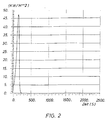
- Fig. 2 shows the course of the heat flow at the time at the stagnation point (nutrition) for the capsule shown in Fig. 1 with a mass of 50 kg, one Resistance coefficient of 1.5, and a cross-sectional area of 9.62 m2.
- the temperatures can be reduced from approximately 1600 ° C to less than 700 ° C.
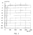
- Fig. 3 shows a representation of the aerodynamic braking of the device shown in Fig. 1 with the previously mentioned low ballistic factor B. Due to the large heat shield, the device is significantly slowed down in the deeper layers of the air envelope, with a stable sinking speed of at sea level approx. 10 m / s is reached, as is usual with capsules with conventional parachutes.
- FIG. 4 shows a preferred embodiment of a device 10 with an unfolded heat shield 13, which consists of elastic reinforcing elements or stringers 14 and a hollow film shape 15 and is wound around a central section of the re-entry body 11.
- a pressure bottle 16 with propellant gas and a pressure bottle 17 with foam are arranged in the interior of the re-entry body 11 and are connected to the interior of the hollow film mold 15 via valves 18, 19.
- the stringers 14 move automatically into the desired position.
- FIG. 5 shows the first phase of the unfolding sequence, the direction of movement of the stringer 14 being shown by arrows when unfolding.
- the stringers 14 are connected to one another in a manner not shown with fiber fabric (carbon / gas fiber etc.). When foaming creates a fiber composite material, which is additionally reinforced by the stringer 14, so that with the intended shape of the Heat shield 13 forming film hollow mold 15 is a stable large-area, lightweight capsule-shaped heat shield is produced, as shown in perspective in Fig. 6.
- Fiber-reinforced plastics that can be used for the device 10 according to the invention only need to meet low thermal and mechanical requirements, since due to the design of the device according to the invention only relatively low temperatures occur and the aerodynamic forces act directly on the heaviest part of the device forming a missile, namely the heat shield. As a result, only small bending moments occur. With a density of the heat shield of approx. 0.5 g / cm3 and a thickness of approx. 0.5 cm, a weight of approx. 24 kg can be realized for the heat shield.
- the heat shield 13 has rotation-producing aerodynamic elements, not shown, which consist of flaps on the outer edge of the heat shield 13 or, preferably, of shapes incorporated into the heat shield 13.
- the design of the device according to the invention advantageously allows a much smaller landing shock than conventional capsules to be expected for landing, since here the heat shield hits the floor and provides a pronounced "floor effect” which brakes the re-entry body 11 and thereby produces shocks.
- This "bottom effect” is due to the fact that the distance between the heat shield and the ground shortly before it strikes is less than the diameter of the heat shield.
- the heat shield can also be designed as a shock absorber.
Landscapes
- Engineering & Computer Science (AREA)
- Remote Sensing (AREA)
- Aviation & Aerospace Engineering (AREA)
- Aiming, Guidance, Guns With A Light Source, Armor, Camouflage, And Targets (AREA)
- Toys (AREA)
- Laminated Bodies (AREA)
- Braking Arrangements (AREA)
- Lining And Supports For Tunnels (AREA)
Priority Applications (1)
| Application Number | Priority Date | Filing Date | Title |
|---|---|---|---|
| AT90118658T ATE96386T1 (de) | 1989-10-14 | 1990-09-28 | Vorrichtung fuer den ruecktransport von kleinen lasten aus dem orbit. |
Applications Claiming Priority (2)
| Application Number | Priority Date | Filing Date | Title |
|---|---|---|---|
| DE3934346A DE3934346A1 (de) | 1989-10-14 | 1989-10-14 | Vorrichtung fuer den ruecktransport von kleinen nutzlasten aus dem orbit |
| DE3934346 | 1989-10-14 |
Publications (2)
| Publication Number | Publication Date |
|---|---|
| EP0427941A1 EP0427941A1 (de) | 1991-05-22 |
| EP0427941B1 true EP0427941B1 (de) | 1993-10-27 |
Family
ID=6391479
Family Applications (1)
| Application Number | Title | Priority Date | Filing Date |
|---|---|---|---|
| EP90118658A Expired - Lifetime EP0427941B1 (de) | 1989-10-14 | 1990-09-28 | Vorrichtung für den Rücktransport von kleinen Lasten aus dem Orbit |
Country Status (4)
| Country | Link |
|---|---|
| EP (1) | EP0427941B1 (OSRAM) |
| AT (1) | ATE96386T1 (OSRAM) |
| DE (1) | DE3934346A1 (OSRAM) |
| ES (1) | ES2047795T3 (OSRAM) |
Cited By (1)
| Publication number | Priority date | Publication date | Assignee | Title |
|---|---|---|---|---|
| IT202300026901A1 (it) * | 2023-12-18 | 2025-06-18 | Univ Pisa | Dispositivo di deorbitazione passiva |
Families Citing this family (5)
| Publication number | Priority date | Publication date | Assignee | Title |
|---|---|---|---|---|
| US5242134A (en) * | 1992-05-22 | 1993-09-07 | The United States Of America As Represented By The Administrator Of The National Aeronautics And Space Administration | Space station trash removal system |
| DE10043268A1 (de) * | 2000-08-28 | 2002-03-14 | Valeri Beck | Verfahren zum Wärme- und/oder aerodynamischen Schutz für ein Raumschiff oder für eine wiederstartbare Raketenstufe bei der Rückkehr |
| DE102006046572B4 (de) * | 2006-09-30 | 2013-07-18 | Astrium Gmbh | Entfaltbare Brems-Struktur für Raumfahrzeuge |
| CN103662099B (zh) * | 2012-09-20 | 2015-12-09 | 中国科学院沈阳自动化研究所 | 一种空间展开结构 |
| CN112722337B (zh) * | 2021-01-23 | 2022-06-07 | 吉林大学 | 一种基于记忆合金的梯度吸能内芯行星探测缓冲着陆腿 |
Family Cites Families (5)
| Publication number | Priority date | Publication date | Assignee | Title |
|---|---|---|---|---|
| US3118636A (en) * | 1959-01-08 | 1964-01-21 | Avco Mfg Corp | Space vehicle |
| US3286951A (en) * | 1963-09-27 | 1966-11-22 | Douglas Aircraft Co Inc | Recovery system |
| US3433435A (en) * | 1966-07-25 | 1969-03-18 | Gen Electric | Tension string drag structures for planetary entry vehicle |
| US3433437A (en) * | 1967-01-18 | 1969-03-18 | John E Reilly | Rocket projectile |
| US4504031A (en) * | 1979-11-01 | 1985-03-12 | The Boeing Company | Aerodynamic braking and recovery method for a space vehicle |
-
1989
- 1989-10-14 DE DE3934346A patent/DE3934346A1/de active Granted
-
1990
- 1990-09-28 EP EP90118658A patent/EP0427941B1/de not_active Expired - Lifetime
- 1990-09-28 ES ES90118658T patent/ES2047795T3/es not_active Expired - Lifetime
- 1990-09-28 AT AT90118658T patent/ATE96386T1/de not_active IP Right Cessation
Cited By (1)
| Publication number | Priority date | Publication date | Assignee | Title |
|---|---|---|---|---|
| IT202300026901A1 (it) * | 2023-12-18 | 2025-06-18 | Univ Pisa | Dispositivo di deorbitazione passiva |
Also Published As
| Publication number | Publication date |
|---|---|
| ES2047795T3 (es) | 1994-03-01 |
| DE3934346C2 (OSRAM) | 1991-11-07 |
| ATE96386T1 (de) | 1993-11-15 |
| EP0427941A1 (de) | 1991-05-22 |
| DE3934346A1 (de) | 1991-04-25 |
Similar Documents
| Publication | Publication Date | Title |
|---|---|---|
| DE68916502T2 (de) | Raketengetriebenes, in der luft entfaltetes, auftriebsunterstütztes raumfahrzeug für orbitale, supraorbitale und suborbitale flüge. | |
| EP1905691B1 (de) | Raumfahrzeug mit einer Vorrichtung zum Hitzeschutz und zum Abbremsen | |
| DE3827279C2 (OSRAM) | ||
| US3181821A (en) | Space craft soft landing system | |
| DE69005552T2 (de) | Verfahren zum Starten einer Kapsel im Raum und Mittel zum Starten. | |
| DE69225526T2 (de) | Modulare Feststoffträgerrakete und Abschusssystem | |
| DE4409424C1 (de) | Abfangvorrichtung für Flugobjekte | |
| EP0861780A1 (de) | Verfahren zur Verhinderung des Überschlagens bei der Landung eines Luft- oder Raumfahrtgerätes | |
| EP0427941B1 (de) | Vorrichtung für den Rücktransport von kleinen Lasten aus dem Orbit | |
| DE102017113058B4 (de) | Raumtransport-Fluggerät | |
| EP4200530B1 (de) | Textile tragflügelstruktur für ein flügelsystem sowie transportgerät | |
| Akin | The parashield entry vehicle concept: Basic theory and flight test development | |
| DE69505423T2 (de) | Aerodynamischer Bremsschild für Raumfahrzeug und damit ausgerüstete Satelliten | |
| WO2011082979A2 (de) | Prüfvorrichtung, prüfsystem für acc-systeme | |
| DE102014019398A1 (de) | Rückkehrender Starteinrichtung für einen Weltraumrakete und das Startverfahren | |
| DE68904184T2 (de) | Startverfahren fuer eine sekundaere nutzlast. | |
| Wang et al. | Airdrop recovery systems with self-inflating airbag: modeling and analysis | |
| DE19610370C1 (de) | Landeverfahren für Nutzlasten aus Luft- und Raumfahrtmissionen | |
| DE4422617C1 (de) | Verfahren zur Dämpfung des Landestoßes | |
| DE3040118A1 (de) | Verfahren und vorrichtung zum zwangsweisen oeffnen eines fallschirms | |
| WO2000034122A1 (de) | Verfahren zum transport einer nutzlast in den weltraum | |
| DE3825174A1 (de) | Rettungseinheit fuer besatzungspersonal von raumtransportern | |
| Vergnolle | Soft landing impact attenuation techologies review | |
| DE19526907C1 (de) | Einrichtung zur Signaturreduzierung | |
| EP0077954A2 (de) | Flugkörper |
Legal Events
| Date | Code | Title | Description |
|---|---|---|---|
| PUAI | Public reference made under article 153(3) epc to a published international application that has entered the european phase |
Free format text: ORIGINAL CODE: 0009012 |
|
| AK | Designated contracting states |
Kind code of ref document: A1 Designated state(s): AT BE CH DK ES FR GB GR IT LI LU NL SE |
|
| 17P | Request for examination filed |
Effective date: 19910704 |
|
| 17Q | First examination report despatched |
Effective date: 19920716 |
|
| GRAA | (expected) grant |
Free format text: ORIGINAL CODE: 0009210 |
|
| AK | Designated contracting states |
Kind code of ref document: B1 Designated state(s): AT BE CH DK ES FR GB GR IT LI LU NL SE |
|
| PG25 | Lapsed in a contracting state [announced via postgrant information from national office to epo] |
Ref country code: GR Free format text: LAPSE BECAUSE OF FAILURE TO SUBMIT A TRANSLATION OF THE DESCRIPTION OR TO PAY THE FEE WITHIN THE PRESCRIBED TIME-LIMIT Effective date: 19931027 Ref country code: DK Effective date: 19931027 |
|
| REF | Corresponds to: |
Ref document number: 96386 Country of ref document: AT Date of ref document: 19931115 Kind code of ref document: T |
|
| ET | Fr: translation filed | ||
| GBT | Gb: translation of ep patent filed (gb section 77(6)(a)/1977) |
Effective date: 19931208 |
|
| ITF | It: translation for a ep patent filed | ||
| REG | Reference to a national code |
Ref country code: ES Ref legal event code: FG2A Ref document number: 2047795 Country of ref document: ES Kind code of ref document: T3 |
|
| PLBE | No opposition filed within time limit |
Free format text: ORIGINAL CODE: 0009261 |
|
| STAA | Information on the status of an ep patent application or granted ep patent |
Free format text: STATUS: NO OPPOSITION FILED WITHIN TIME LIMIT |
|
| PG25 | Lapsed in a contracting state [announced via postgrant information from national office to epo] |
Ref country code: AT Effective date: 19940928 |
|
| PG25 | Lapsed in a contracting state [announced via postgrant information from national office to epo] |
Ref country code: LU Free format text: LAPSE BECAUSE OF NON-PAYMENT OF DUE FEES Effective date: 19940930 Ref country code: LI Effective date: 19940930 Ref country code: CH Effective date: 19940930 |
|
| 26N | No opposition filed | ||
| EAL | Se: european patent in force in sweden |
Ref document number: 90118658.5 |
|
| REG | Reference to a national code |
Ref country code: CH Ref legal event code: PL |
|
| PGFP | Annual fee paid to national office [announced via postgrant information from national office to epo] |
Ref country code: BE Payment date: 19980805 Year of fee payment: 9 |
|
| PGFP | Annual fee paid to national office [announced via postgrant information from national office to epo] |
Ref country code: SE Payment date: 19980810 Year of fee payment: 9 |
|
| PGFP | Annual fee paid to national office [announced via postgrant information from national office to epo] |
Ref country code: GB Payment date: 19980914 Year of fee payment: 9 |
|
| PGFP | Annual fee paid to national office [announced via postgrant information from national office to epo] |
Ref country code: NL Payment date: 19980929 Year of fee payment: 9 |
|
| PGFP | Annual fee paid to national office [announced via postgrant information from national office to epo] |
Ref country code: FR Payment date: 19980930 Year of fee payment: 9 Ref country code: ES Payment date: 19980930 Year of fee payment: 9 |
|
| PG25 | Lapsed in a contracting state [announced via postgrant information from national office to epo] |
Ref country code: GB Free format text: LAPSE BECAUSE OF NON-PAYMENT OF DUE FEES Effective date: 19990928 |
|
| PG25 | Lapsed in a contracting state [announced via postgrant information from national office to epo] |
Ref country code: SE Free format text: THE PATENT HAS BEEN ANNULLED BY A DECISION OF A NATIONAL AUTHORITY Effective date: 19990929 Ref country code: ES Free format text: LAPSE BECAUSE OF NON-PAYMENT OF DUE FEES Effective date: 19990929 |
|
| PG25 | Lapsed in a contracting state [announced via postgrant information from national office to epo] |
Ref country code: BE Free format text: LAPSE BECAUSE OF NON-PAYMENT OF DUE FEES Effective date: 19990930 |
|
| BERE | Be: lapsed |
Owner name: ERNO RAUMFAHRTTECHNIK G.M.B.H. Effective date: 19990930 |
|
| PG25 | Lapsed in a contracting state [announced via postgrant information from national office to epo] |
Ref country code: NL Free format text: LAPSE BECAUSE OF NON-PAYMENT OF DUE FEES Effective date: 20000401 |
|
| EUG | Se: european patent has lapsed |
Ref document number: 90118658.5 |
|
| GBPC | Gb: european patent ceased through non-payment of renewal fee |
Effective date: 19990928 |
|
| PG25 | Lapsed in a contracting state [announced via postgrant information from national office to epo] |
Ref country code: FR Free format text: LAPSE BECAUSE OF NON-PAYMENT OF DUE FEES Effective date: 20000531 |
|
| NLV4 | Nl: lapsed or anulled due to non-payment of the annual fee |
Effective date: 20000401 |
|
| REG | Reference to a national code |
Ref country code: FR Ref legal event code: ST |
|
| REG | Reference to a national code |
Ref country code: ES Ref legal event code: FD2A Effective date: 20001013 |
|
| PG25 | Lapsed in a contracting state [announced via postgrant information from national office to epo] |
Ref country code: IT Free format text: LAPSE BECAUSE OF NON-PAYMENT OF DUE FEES;WARNING: LAPSES OF ITALIAN PATENTS WITH EFFECTIVE DATE BEFORE 2007 MAY HAVE OCCURRED AT ANY TIME BEFORE 2007. THE CORRECT EFFECTIVE DATE MAY BE DIFFERENT FROM THE ONE RECORDED. Effective date: 20050928 |