EP0427663B1 - Hydraulic drilling device and method for use - Google Patents
Hydraulic drilling device and method for use Download PDFInfo
- Publication number
- EP0427663B1 EP0427663B1 EP90810755A EP90810755A EP0427663B1 EP 0427663 B1 EP0427663 B1 EP 0427663B1 EP 90810755 A EP90810755 A EP 90810755A EP 90810755 A EP90810755 A EP 90810755A EP 0427663 B1 EP0427663 B1 EP 0427663B1
- Authority
- EP
- European Patent Office
- Prior art keywords
- hydraulic
- thrust
- drilling
- control
- hammer drill
- Prior art date
- Legal status (The legal status is an assumption and is not a legal conclusion. Google has not performed a legal analysis and makes no representation as to the accuracy of the status listed.)
- Expired - Lifetime
Links
- 238000005553 drilling Methods 0.000 title claims abstract description 27
- 238000000034 method Methods 0.000 title claims 3
- 230000033001 locomotion Effects 0.000 claims abstract description 12
- 238000011010 flushing procedure Methods 0.000 claims abstract description 11
- XLYOFNOQVPJJNP-UHFFFAOYSA-N water Substances O XLYOFNOQVPJJNP-UHFFFAOYSA-N 0.000 claims abstract description 7
- 239000007788 liquid Substances 0.000 claims description 4
- 238000001816 cooling Methods 0.000 claims description 3
- 238000013016 damping Methods 0.000 claims description 3
- 238000005065 mining Methods 0.000 description 4
- 239000008237 rinsing water Substances 0.000 description 3
- 230000005540 biological transmission Effects 0.000 description 2
- 238000002485 combustion reaction Methods 0.000 description 2
- 239000000498 cooling water Substances 0.000 description 2
- 230000008878 coupling Effects 0.000 description 2
- 238000010168 coupling process Methods 0.000 description 2
- 238000005859 coupling reaction Methods 0.000 description 2
- 239000012530 fluid Substances 0.000 description 2
- 230000007935 neutral effect Effects 0.000 description 2
- 239000000654 additive Substances 0.000 description 1
- 239000000839 emulsion Substances 0.000 description 1
- 230000001050 lubricating effect Effects 0.000 description 1
- 239000011435 rock Substances 0.000 description 1
- 239000000725 suspension Substances 0.000 description 1
Images

Classifications
-
- E—FIXED CONSTRUCTIONS
- E21—EARTH OR ROCK DRILLING; MINING
- E21B—EARTH OR ROCK DRILLING; OBTAINING OIL, GAS, WATER, SOLUBLE OR MELTABLE MATERIALS OR A SLURRY OF MINERALS FROM WELLS
- E21B44/00—Automatic control systems specially adapted for drilling operations, i.e. self-operating systems which function to carry out or modify a drilling operation without intervention of a human operator, e.g. computer-controlled drilling systems; Systems specially adapted for monitoring a plurality of drilling variables or conditions
- E21B44/02—Automatic control of the tool feed
- E21B44/06—Automatic control of the tool feed in response to the flow or pressure of the motive fluid of the drive
-
- E—FIXED CONSTRUCTIONS
- E21—EARTH OR ROCK DRILLING; MINING
- E21B—EARTH OR ROCK DRILLING; OBTAINING OIL, GAS, WATER, SOLUBLE OR MELTABLE MATERIALS OR A SLURRY OF MINERALS FROM WELLS
- E21B19/00—Handling rods, casings, tubes or the like outside the borehole, e.g. in the derrick; Apparatus for feeding the rods or cables
- E21B19/08—Apparatus for feeding the rods or cables; Apparatus for increasing or decreasing the pressure on the drilling tool; Apparatus for counterbalancing the weight of the rods
- E21B19/087—Apparatus for feeding the rods or cables; Apparatus for increasing or decreasing the pressure on the drilling tool; Apparatus for counterbalancing the weight of the rods by means of a swinging arm
-
- E—FIXED CONSTRUCTIONS
- E21—EARTH OR ROCK DRILLING; MINING
- E21B—EARTH OR ROCK DRILLING; OBTAINING OIL, GAS, WATER, SOLUBLE OR MELTABLE MATERIALS OR A SLURRY OF MINERALS FROM WELLS
- E21B21/00—Methods or apparatus for flushing boreholes, e.g. by use of exhaust air from motor
- E21B21/01—Arrangements for handling drilling fluids or cuttings outside the borehole, e.g. mud boxes
-
- E—FIXED CONSTRUCTIONS
- E21—EARTH OR ROCK DRILLING; MINING
- E21B—EARTH OR ROCK DRILLING; OBTAINING OIL, GAS, WATER, SOLUBLE OR MELTABLE MATERIALS OR A SLURRY OF MINERALS FROM WELLS
- E21B6/00—Drives for drilling with combined rotary and percussive action
Definitions
- the invention relates to a hydraulic drilling device, which consists of a hydraulically driven hammer drill and a hydraulic feed unit with a control of the hydraulics.
- Hydraulic drilling rigs are used to drill mounting holes and blast holes in the rock. A preferred area is mining. An overview of the status of hydraulic drilling rigs can be found in the article "Hydraulic Rockdrills" by Joffrey Pearse (Mining Magazine - March 1985, pages 221 to 231, Mining Journal Ltd., 60 Worshipstreet, London EC2A 2HD), in which the products of various manufacturers and their application are described. Telescopic cylinders for generating the feed and retraction movement are known for hand-operated rotary hammers and for drilling equipment on carriages, hydraulic feed and retraction devices on rotary hammers so far as elements of closed ones hydraulic circuits can be operated with oil or with water emulsions.
- the invention provides a remedy here. It solves the task of reducing the number of flexible supply lines and flexible internal connecting lines of a hydraulic drilling device to a minimum and the location of the supply device within wide limits, e.g. in mining on the surface of the earth.
- the object is achieved by using the cooling and rinsing water for the drill bit as an energy source for all movements carried out by the drilling device, by using a single hydraulic supply line from outside the drilling unit as an energy source for driving the feed unit, as well as for the drive and rinsing the drill bit to the Control is performed on the device, and by installing only a single hydraulic supply line to the hammer drill from the hydraulic feed unit with control, which transmits the drive power for the hammer drill and the flushing fluid for the drill bit.
- the missing geodetic gradient for the operation of the drilling device is generated by pressure booster pumps somewhere between the water reservoir and the drilling machine and after the pump, the flushing water network is designed to be more powerful in accordance with the pressure increase.
- the drilling device is equipped with a minimum of supply lines, which simplifies handling, and that, by using rinsing water as an energy source for drilling, no further electric motors or internal combustion engines with their necessary infrastructure on site or below Days are necessary.
- a hydraulic drilling device which consists of a hydraulically driven hammer drill 1, which is pivotally attached to a hydraulic feed unit 10 and a hydraulic feed unit 10 with a control 14 of the hydraulic system, with cooling and rinsing water according to the invention for the drill bit 3 is used as an energy source for all movements carried out by the drill.
- a single hydraulic supply line 6 with coupling piece 4 is guided from outside the drill as an energy source for driving the feed unit 10 and for driving and flushing the drill bit 3 to the control 14 and is only a single hydraulic supply line 5 with coupling pieces 4 from the hydraulic feed unit 10 with controller 14 to the hammer drill 1, which transmits the drive power for the hammer drill 1 and the flushing air liquid for the drill bit 3.
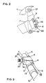
- the hammer drill 1 with handle 2 and with inserted drill bit 3 is connected to an intermediate piece 7 of the feed unit 10 via a transmission piece 8 by hinge bolts 17, 18.
- a connecting web 23 of the transmission piece 8 is fixed via a retaining screw 16 between a damping disk 19 and a damping device 9.
- the feed and retraction movement is transmitted via a foot 15 supported on the floor by an actuating cylinder 12 with a piston acted on on both sides via a guided piston rod 11 to the housing of the control part 14 and through the intermediate piece 7 and that Transfer piece 8 passed to the hammer drill 1.
- the piston surfaces are pressurized by channels in the hollow piston rod 11 on the side towards the support foot 15 and on the other side towards the cylinder cover 13.
- a rotary valve 20 which can be rotated between two end positions via an actuating lever 22, the reversal between the feed movement and the retracting movement is carried out on the one hand by rotating over a neutral locking angle and on the other hand the hydraulic feed line 5 with energy and flushing water to the hammer drill 1 is blocked as soon as the rotary valve 20 is turned from the feed area into the neutral locking angle.
- the maximum feed rate is specified by changing a throttle point by setting the setpoint by turning a feed setting 21, which for operational reasons is preferably built on the rotary valve 20 itself.
Landscapes
- Engineering & Computer Science (AREA)
- Geology (AREA)
- Life Sciences & Earth Sciences (AREA)
- Mining & Mineral Resources (AREA)
- Physics & Mathematics (AREA)
- Environmental & Geological Engineering (AREA)
- Fluid Mechanics (AREA)
- General Life Sciences & Earth Sciences (AREA)
- Geochemistry & Mineralogy (AREA)
- Mechanical Engineering (AREA)
- Earth Drilling (AREA)
- Soil Working Implements (AREA)
- Lubricants (AREA)
- Measuring Fluid Pressure (AREA)
Abstract
Description
Die Erfindung betrifft ein hydraulisches Bohrgerät, das aus einem hydraulisch angetriebenen Bohrhammer und aus einer hydraulischen Vorschubeinheit mit einer Steuerung der Hydraulik besteht.The invention relates to a hydraulic drilling device, which consists of a hydraulically driven hammer drill and a hydraulic feed unit with a control of the hydraulics.
Hydraulische Bohrgeräte werden beim Bohren von Befestigungslöchern und von Sprenglöchern im Gestein eingesetzt. Ein bevorzugtes Gebiet ist der Bergbau. Eine Übersicht über den Stand der hydraulischen Bohrgeräte findet sich im Artikel "Hydraulic Rockdrills" von Joffrey Pearse (Mining Magazine - March 1985, Seite 221 bis 231, Mining Journal Ltd., 60 Worshipstreet, London EC2A 2HD), in dem die Produkte verschiedener Hersteller und ihre Anwendung beschrieben sind. Teleskopzylinder zur Erzeugung der Vorschub- und Rückzugsbewegung sind für handbetätigte Bohrhammer und für Bohrgeräte auf Lafetten bekannt, wobei hydraulische Vorschub- und Rückzugseinrichtungen an Bohrhämmern bisher als Elemente von geschlossenen hydraulischen Kreisläufen mit Öl oder mit Wasseremulsionen betrieben werden. Beim Bohren mit diesen Geräten besteht eine grosse Abhängigkeit in der maximalen Distanz zur Oel- resp. Flüssigkeitsversorgung, die den Flüssigkeitsströmen die notwendige Leistung abgibt. Neben den Spülleitungen für den Bohrmeissel werden Bohrantrieb und Vorschubregelung oft über getrennte Druckleitungen versorgt, so dass zusammen mit den Rücklaufleitungen eine Vielzahl von mehr oder weniger flexiblen Leitungen im Bedienungsbereich des Bohrgerätes liegt. Diese Leitungen behindern die Bewegungsmöglichkeiten; sie dürfen nicht verletzt werden und sie müssen sich entsprechend dem Vortrieb nachziehen lassen. Bisher sind geschlossene Kreisläufe wegen der Entflammbarkeit oder wegen der Kosten bei mit Schmierzusätzen versehenen Energieträgern notwendig. Die hydraulische Versorgungseinheit muss wegen der Druckverluste aus erhöhter Viskosität, sowie wegen der Aufwendungen für die Antriebsflüssigkeit in einem möglichst geringen Abstand von maximal wenigen hundert Metern zum Bohrgerät, z.B. auf der gleichen Sohle eines Bergwerks, aufgestellt werden.Hydraulic drilling rigs are used to drill mounting holes and blast holes in the rock. A preferred area is mining. An overview of the status of hydraulic drilling rigs can be found in the article "Hydraulic Rockdrills" by Joffrey Pearse (Mining Magazine - March 1985, pages 221 to 231, Mining Journal Ltd., 60 Worshipstreet, London EC2A 2HD), in which the products of various manufacturers and their application are described. Telescopic cylinders for generating the feed and retraction movement are known for hand-operated rotary hammers and for drilling equipment on carriages, hydraulic feed and retraction devices on rotary hammers so far as elements of closed ones hydraulic circuits can be operated with oil or with water emulsions. When drilling with these devices, there is a large dependency in the maximum distance to the oil or. Liquid supply that delivers the necessary power to the liquid flows. In addition to the flushing lines for the drill bit, the drill drive and feed control are often supplied via separate pressure lines, so that together with the return lines there are a large number of more or less flexible lines in the operating area of the drill. These lines hinder the possibilities of movement; they must not be injured and they must be able to be pulled according to the propulsion. Closed circuits have hitherto been necessary because of the flammability or because of the costs of energy sources provided with lubricating additives. The hydraulic supply unit must be set up at a minimum distance of a few hundred meters from the drill, for example on the same base of a mine, because of the pressure losses from increased viscosity and because of the expenditure for the drive fluid.
Hier schafft die Erfindung Abhilfe. Sie löst die Aufgabe, die Anzahl von flexiblen Zuleitungen und an flexiblen internen Verbindungsleitungen eines hydraulischen Bohrgerätes auf ein Minimum zu reduzieren und den Standort des Versorgungsgerätes in weiten Grenzen, z.B. im Bergbau an der Erdoberfläche, wählen zu können.The invention provides a remedy here. It solves the task of reducing the number of flexible supply lines and flexible internal connecting lines of a hydraulic drilling device to a minimum and the location of the supply device within wide limits, e.g. in mining on the surface of the earth.
Gemäss der Erfindung wird die Aufgabe gelöst, indem das Kühl- und Spülwasser für den Bohrmeissel als Energieträger für sämtliche vom Bohrgerät durchgeführten Bewegungen verwendet wird, indem eine einzige hydraulische Versorgungsleitung von ausserhalb des Bohrgerätes als Energieträger für den Antrieb der Vorschubeinheit, sowie für den Antrieb und das Spülen des Bohrmeissels zu der Steuerung am Gerät geführt ist, und indem von der hydraulischen Vorschubeinheit mit Steuerung nur eine einzige hydraulische Zuleitung zum Bohrhammer installiert ist, die die Antriebsleistung für den Bohrhammer und die Spülflüssigkeit für den Bohrmeissel überträgt. Das für den Betrieb des Bohrgerätes fehlende geodätische Gefälle wird durch Druckerhöhungspumpen irgendwo zwischen Wasserreservoir und Bohrgerät erzeugt und nach der Pumpe wird das Spülwassernetz entsprechend der Druckerhöhung stärker ausgelegt.According to the invention, the object is achieved by using the cooling and rinsing water for the drill bit as an energy source for all movements carried out by the drilling device, by using a single hydraulic supply line from outside the drilling unit as an energy source for driving the feed unit, as well as for the drive and rinsing the drill bit to the Control is performed on the device, and by installing only a single hydraulic supply line to the hammer drill from the hydraulic feed unit with control, which transmits the drive power for the hammer drill and the flushing fluid for the drill bit. The missing geodetic gradient for the operation of the drilling device is generated by pressure booster pumps somewhere between the water reservoir and the drilling machine and after the pump, the flushing water network is designed to be more powerful in accordance with the pressure increase.
Die Vorteile der Erfindung sind darin zu sehen, dass das Bohrgerät mit einem Minimum von Versorgungsleitungen ausgestattet ist, was die Handhabung erleichtert, und dass durch die Verwendung von Spülwasser als Energieträger für das Bohren keine weiteren Elektromotoren oder Verbrennungsmotoren mit ihrer notwendigen Infrastruktur vor Ort oder unter Tage notwendig sind.The advantages of the invention can be seen in the fact that the drilling device is equipped with a minimum of supply lines, which simplifies handling, and that, by using rinsing water as an energy source for drilling, no further electric motors or internal combustion engines with their necessary infrastructure on site or below Days are necessary.
Für das Bohren vor Ort sind unter Tage keine Aufwendungen für elektrischen Kraftstrom oder für Abluftleitungen von Verbrennungsmotoren notwendig.For drilling on site, no expenses for electrical power or for exhaust air lines from internal combustion engines are necessary.
Im folgenden wird die Erfindung anhand von einem Ausführungsbeispiel beschrieben. Es zeigen:
- Fig. 1 eine schematische Seitenansicht eines hydraulischen Bohrgerätes mit Bohrhammer und Vorschubeinheit;
- Fig. 2 einen vergrösserten Ausschnitt der Seitenansicht von Fig. 1 mit der Aufhängung zwischen Bohrhammer und Vorschubeinheit und
- Fig. 3 einen vergrösserten Ausschnitt oder Draufsicht auf die Vorschubeinheit mit Steuerung von der Bedienungsseite aus.
- Figure 1 is a schematic side view of a hydraulic drill with hammer drill and feed unit.
- Fig. 2 is an enlarged detail of the side view of Fig. 1 with the suspension between hammer drill and feed unit and
- Fig. 3 is an enlarged section or top view of the feed unit with control from the operator side.
In den Figuren ist ein hydraulisches Bohrgerät gezeigt, das aus einem hydraulisch angetriebenen Bohrhammer 1 besteht, der schwenkbar an einer hydraulischen Vorschubeinheit 10 befestigt ist und aus einer hydraulischen Vorschubeinheit 10 mit einer Steuerung 14 der Hydraulik, wobei erfindungsgemäss Kühl- und Spülwasser für den Bohrmeissel 3 als Energieträger für sämtliche vom Bohrgerät durchgeführte Bewegungen verwendet wird. Im weiteren ist eine einzige hydraulische Versorungsleitung 6 mit Kupplungsstück 4 von ausserhalb des Bohrgerätes als Energieträger für den Antrieb der Vorschubeinheit 10 sowie für den Antrieb und das Spülen des Bohrmeissels 3 zu der Steuerung 14 geführt und ist nur eine einzige hydraulische Zuleitung 5 mit Kupplungsstücken 4 von der hydraulischen Vorschubeinheit 10 mit Steuerung 14 zum Bohrhammer 1 installiert, die die Antriebsleistung für den Bohrhammer 1 und die Spülluftflüssigkeit für den Bohrmeissel 3 überträgt.In the figures, a hydraulic drilling device is shown, which consists of a hydraulically driven
Der Bohrhammer 1 mit Haltegriff 2 und mit eingesetztem Bohrmeissel 3 ist über ein Uebertragungsstück 8 durch Scharnierbolzen 17, 18 mit einem Zwischenstück 7 der Vorschubeinheit 10 verbunden.The
Ein Verbindungssteg 23 des Übertragungsstückes 8 ist über eine Halteschraube 16 zwischen einer Dämpfungsscheibe 19 und einer Dämpfungseinrichtung 9 fixiert. Die Vorschub- und Rückzugsbewegung wird über einen am Boden abgestüzten Fuss 15 durch einen Stellzylinder 12 mit einem beidseitig beaufschlagten Kolben über eine geführte Kolbenstange 11 auf das Gehäuse vom Steuerteil 14 übertragen und durch das Zwischenstück 7 und das Übertragungsstück 8 an den Bohrhammer 1 weitergegeben. Die Kolbenflächen werden durch Kanäle in der hohlen Kolbenstange 11 einmal auf der Seite zum Abstützfuss 15 und zum anderen auf der Seite zum Zylinderdeckel 13 hin mit Druck beaufschlagt.A connecting
Mit einem Drehschieber 20, der über einen Betätigungshebel 22 zwischen zwei Endlagen gedreht werden kann, wird zum einen über einen neutralen Sperrwinkel hinwegdrehend die Umsteuerung zwischen Vorschubbewegung und Rückzugsbewegung vorgenommen und zum anderen die hydraulische Zuleitung 5 mit Energie- und Spülwasser zum Bohrhammer 1 gesperrt, sobald der Drehschieber 20 aus dem Vorschubbereich in den neutralen Sperrwinkel hineingedreht wird. Die maximale Vorschubgeschwindigkeit wird durch Veränderung einer Drosselstelle vorgegeben, indem der Sollwert durch Verdrehen einer Vorschubeinstellung 21 eingestellt wird, die aus Bedienungsgründen vorzugsweise auf dem Drehschieber 20 selbst aufgebaut ist.With a
Claims (6)
- A hydraulic drilling outfit consisting of a hydraulically driven hammer drill (1) and a hydraulic thrust unit (10) with a control (14) for the hydraulics,
characterized in that one single hydraulic supply line (6) is led from outside the drilling outfit to the control (14) as the power-bearer for the drive of the thrust unit (10) as well as for the drive and flushing of a drill bit (3), and that from the hydraulic thrust unit (10) with the control (14) only one single hydraulic connecting line (5) is installed to the hammer drill (1) to transmit the driving power for the hammer drill (1) and the flushing liquid for the drill bit (3). - A hydraulic drilling outfit as in Claim 1,
characterized in that the swivelling connection between the hammer drill (1) and the thrust unit (10) exhibits damping (19, 9) by springy elements, which may be set differently in the thrust and withdrawal directions. - A hydraulic drilling outfit as in one of the Claims 1 or 2, characterized in that the hydraulic control (14) exhibits one central rotary slidevalve (20) which on the one hand between the two end positions of its actuating lever (22) controls the thrust and withdrawal motions of the thrust unit (10) as well as the operation and non-operation of the hammer drill (1) and to which on the other hand a settable desired-value adjustment (21) is fitted for the regulation of the thrust motion.
- A hydraulic drilling outfit as in one of the Claims 1 to 3, characterized in that no return line is installed from the drilling outfit to the hydraulic supply.
- A method of operation of a hydraulic drilling outfit as in Claims 1 to 4, characterized in that cooling and flushing water for the drill bit (3) is employed as power-bearer for all of the motions performed by the drilling outfit.
- A method as in Claim 5, characterized in that the supply of water for power and flushing is performed in open circuit.
Priority Applications (1)
| Application Number | Priority Date | Filing Date | Title |
|---|---|---|---|
| AT90810755T ATE86714T1 (en) | 1989-11-08 | 1990-10-03 | HYDRAULIC DRILLING RIG AND METHOD OF OPERATING THE RIG. |
Applications Claiming Priority (2)
| Application Number | Priority Date | Filing Date | Title |
|---|---|---|---|
| CH402789 | 1989-11-08 | ||
| CH4027/89 | 1989-11-08 |
Publications (2)
| Publication Number | Publication Date |
|---|---|
| EP0427663A1 EP0427663A1 (en) | 1991-05-15 |
| EP0427663B1 true EP0427663B1 (en) | 1993-03-10 |
Family
ID=4268447
Family Applications (1)
| Application Number | Title | Priority Date | Filing Date |
|---|---|---|---|
| EP90810755A Expired - Lifetime EP0427663B1 (en) | 1989-11-08 | 1990-10-03 | Hydraulic drilling device and method for use |
Country Status (9)
| Country | Link |
|---|---|
| US (1) | US5107933A (en) |
| EP (1) | EP0427663B1 (en) |
| JP (1) | JPH03161688A (en) |
| AT (1) | ATE86714T1 (en) |
| AU (1) | AU630750B2 (en) |
| CA (1) | CA2029094A1 (en) |
| DE (1) | DE59001008D1 (en) |
| FI (1) | FI904366A0 (en) |
| ZA (1) | ZA907692B (en) |
Families Citing this family (12)
| Publication number | Priority date | Publication date | Assignee | Title |
|---|---|---|---|---|
| FI904366A0 (en) * | 1989-11-08 | 1990-09-04 | Sulzer Ag | HYDRAULIC BORROWING FOR OVERFLOWERS FOR ANALYZING. |
| DE4433533C1 (en) * | 1994-09-20 | 1995-11-23 | Terra Ag Tiefbautechnik | Hydraulic ram=type drill |
| NO313468B1 (en) * | 2000-12-11 | 2002-10-07 | Per H Moe | Method and apparatus for optimized drilling |
| DE10200309A1 (en) * | 2002-01-07 | 2003-07-17 | Hilti Ag | Feed support device for a portable machine tool |
| CA2415330C (en) * | 2002-12-19 | 2005-03-15 | Danny Morissette | Self-supporting pneumatic hammer positioner with universal joint |
| US7789167B2 (en) * | 2008-04-16 | 2010-09-07 | The Boeing Company | Power assist lever arm attachment |
| DE202011100538U1 (en) * | 2011-05-11 | 2012-08-14 | Max Wild Gmbh | drilling rig |
| CN105386735A (en) * | 2015-12-02 | 2016-03-09 | 湖南科技大学 | Hydraulic feeding device for coal road dry-boring orifice dust collector |
| CN105822304B (en) * | 2016-03-23 | 2017-12-19 | 河南理工大学 | A kind of gob side entry cuts top release orientation waterpower grooving long-range control method |
| WO2019000033A1 (en) * | 2017-06-26 | 2019-01-03 | UGT Group Pty Ltd | Drill assembly and valve |
| CN110056318B (en) * | 2019-04-23 | 2023-12-22 | 中工国际工程股份有限公司 | Anti-blocking device for brine discharge pipe of salt cavern gas storage |
| US11051458B2 (en) * | 2019-08-07 | 2021-07-06 | John Wilson | High reaching pruning apparatus |
Family Cites Families (13)
| Publication number | Priority date | Publication date | Assignee | Title |
|---|---|---|---|---|
| US1164496A (en) * | 1915-04-29 | 1915-12-14 | Sullivan Machinery Co | Rock-drill. |
| US2599042A (en) * | 1947-12-30 | 1952-06-03 | Clyde E Bannister | Excavating apparatus |
| US2908482A (en) * | 1952-07-16 | 1959-10-13 | Joy Mfg Co | Rock drill |
| US3132703A (en) * | 1956-05-15 | 1964-05-12 | Atlas Copco Ab | Rock drilling mechanism |
| US2964305A (en) * | 1958-11-20 | 1960-12-13 | Chicago Pneumatic Tool Co | Crust breaking apparatus |
| US3203489A (en) * | 1963-07-18 | 1965-08-31 | Thor Power Tool Co | Sinker drill |
| US4024923A (en) * | 1972-11-16 | 1977-05-24 | Kenneth Joseph Broadbent | Rock bolting equipment |
| US4010806A (en) * | 1972-11-16 | 1977-03-08 | The Titan Manufacturing Company Proprietary Limited | Rock bolting equipment |
| DE2855575C2 (en) * | 1978-12-22 | 1985-11-21 | Salzgitter Maschinen Und Anlagen Ag, 3320 Salzgitter | Hydraulic drill |
| AT381363B (en) * | 1983-11-08 | 1986-10-10 | Ver Edelstahlwerke Ag | DEVICE FOR IMPACTING DRILLING |
| JPS6255394A (en) * | 1985-09-04 | 1987-03-11 | マツダ株式会社 | Apparatus for measuring tunnel cross-section for rock drill |
| DE3708616A1 (en) * | 1987-03-17 | 1988-09-29 | Schmidt & Co Gmbh Kranz | Tie-drilling apparatus |
| FI904366A0 (en) * | 1989-11-08 | 1990-09-04 | Sulzer Ag | HYDRAULIC BORROWING FOR OVERFLOWERS FOR ANALYZING. |
-
1990
- 1990-09-04 FI FI904366A patent/FI904366A0/en not_active Application Discontinuation
- 1990-09-26 ZA ZA907692A patent/ZA907692B/en unknown
- 1990-10-03 DE DE9090810755T patent/DE59001008D1/en not_active Expired - Fee Related
- 1990-10-03 AT AT90810755T patent/ATE86714T1/en not_active IP Right Cessation
- 1990-10-03 EP EP90810755A patent/EP0427663B1/en not_active Expired - Lifetime
- 1990-10-18 JP JP2280550A patent/JPH03161688A/en active Pending
- 1990-10-25 AU AU64961/90A patent/AU630750B2/en not_active Ceased
- 1990-10-26 US US07/604,051 patent/US5107933A/en not_active Expired - Fee Related
- 1990-10-31 CA CA002029094A patent/CA2029094A1/en not_active Abandoned
Also Published As
| Publication number | Publication date |
|---|---|
| FI904366A0 (en) | 1990-09-04 |
| EP0427663A1 (en) | 1991-05-15 |
| US5107933A (en) | 1992-04-28 |
| AU6496190A (en) | 1991-05-16 |
| CA2029094A1 (en) | 1991-05-09 |
| DE59001008D1 (en) | 1993-04-15 |
| ATE86714T1 (en) | 1993-03-15 |
| JPH03161688A (en) | 1991-07-11 |
| ZA907692B (en) | 1991-07-31 |
| AU630750B2 (en) | 1992-11-05 |
Similar Documents
| Publication | Publication Date | Title |
|---|---|---|
| EP0427663B1 (en) | Hydraulic drilling device and method for use | |
| DE2525817A1 (en) | CONTROL SYSTEM FOR HYDRAULIC OPERATION | |
| EP0863293B1 (en) | Method and apparatus for controlling the push mechanism of an earth drilling rig | |
| EP1102646B1 (en) | Milling device for pipe cleaning and sanitation technology | |
| DE602004005162T2 (en) | HYDRAULIC SYSTEM FOR MINING EQUIPMENT AND METHOD FOR ADJUSTING THE PERFORMANCE OF A CUTTING MACHINE | |
| DE2952303C2 (en) | ||
| WO1996028630A1 (en) | Hydraulic tubing machine as an attachment for a mobile rotary boring installation | |
| WO2002044508A2 (en) | Pneumatic rock-boring device and method for horizontal drilling using compressed air and drilling medium | |
| AT394247B (en) | STONE DRILLING PLANT | |
| DE1171848B (en) | Device and method for driving a borehole | |
| AT393293B (en) | METHOD FOR TURN DRILLING AND TURN DRILL DEVICE | |
| EP0263967B1 (en) | Submersible pile hammer | |
| EP0145701B1 (en) | Percussion drill controls | |
| DE69606048T2 (en) | MULTIPLE-ARTICULATED BOOM FOR WORKING MACHINE | |
| DE1458635A1 (en) | Rock drilling machine | |
| DE2554844A1 (en) | MECHANICAL-HYDRAULIC COMBINES FOR THE EXTRACTION OF COAL | |
| DE3247632C1 (en) | Device for producing an upward borehole | |
| DE2129052C3 (en) | Drill support | |
| DE1484393B1 (en) | DRILLING DEVICE FOR EXTENDING THE SOLE OF A DRILLING HOLE | |
| DE3011449A1 (en) | METHOD AND DEVICE FOR PRODUCING A VERTICAL OR INCLINED HOLE | |
| DE2505396C2 (en) | Drilling rig with a pump for hydraulic support as a pressure generator and a hydrostatic rotary motor | |
| DE10146023B4 (en) | Control for a percussion drive | |
| DE3708616A1 (en) | Tie-drilling apparatus | |
| DE3301029C2 (en) | Control of a mechanical-hydraulic coal mining device | |
| DE3301027C2 (en) | Process for supplying a mechanical-hydraulic coal mining device |
Legal Events
| Date | Code | Title | Description |
|---|---|---|---|
| PUAI | Public reference made under article 153(3) epc to a published international application that has entered the european phase |
Free format text: ORIGINAL CODE: 0009012 |
|
| 17P | Request for examination filed |
Effective date: 19901129 |
|
| AK | Designated contracting states |
Kind code of ref document: A1 Designated state(s): AT CH DE FR GB LI SE |
|
| 17Q | First examination report despatched |
Effective date: 19920818 |
|
| GRAA | (expected) grant |
Free format text: ORIGINAL CODE: 0009210 |
|
| AK | Designated contracting states |
Kind code of ref document: B1 Designated state(s): AT CH DE FR GB LI SE |
|
| REF | Corresponds to: |
Ref document number: 86714 Country of ref document: AT Date of ref document: 19930315 Kind code of ref document: T |
|
| REF | Corresponds to: |
Ref document number: 59001008 Country of ref document: DE Date of ref document: 19930415 |
|
| GBT | Gb: translation of ep patent filed (gb section 77(6)(a)/1977) |
Effective date: 19930322 |
|
| ET | Fr: translation filed | ||
| PGFP | Annual fee paid to national office [announced via postgrant information from national office to epo] |
Ref country code: CH Payment date: 19930910 Year of fee payment: 4 |
|
| PGFP | Annual fee paid to national office [announced via postgrant information from national office to epo] |
Ref country code: DE Payment date: 19930911 Year of fee payment: 4 |
|
| PGFP | Annual fee paid to national office [announced via postgrant information from national office to epo] |
Ref country code: FR Payment date: 19930913 Year of fee payment: 4 |
|
| PGFP | Annual fee paid to national office [announced via postgrant information from national office to epo] |
Ref country code: AT Payment date: 19930914 Year of fee payment: 4 |
|
| PGFP | Annual fee paid to national office [announced via postgrant information from national office to epo] |
Ref country code: SE Payment date: 19930915 Year of fee payment: 4 |
|
| PLBE | No opposition filed within time limit |
Free format text: ORIGINAL CODE: 0009261 |
|
| STAA | Information on the status of an ep patent application or granted ep patent |
Free format text: STATUS: NO OPPOSITION FILED WITHIN TIME LIMIT |
|
| 26N | No opposition filed | ||
| PG25 | Lapsed in a contracting state [announced via postgrant information from national office to epo] |
Ref country code: GB Effective date: 19941003 Ref country code: AT Effective date: 19941003 |
|
| PG25 | Lapsed in a contracting state [announced via postgrant information from national office to epo] |
Ref country code: SE Effective date: 19941004 |
|
| PG25 | Lapsed in a contracting state [announced via postgrant information from national office to epo] |
Ref country code: LI Effective date: 19941031 Ref country code: CH Effective date: 19941031 |
|
| EAL | Se: european patent in force in sweden |
Ref document number: 90810755.0 |
|
| GBPC | Gb: european patent ceased through non-payment of renewal fee |
Effective date: 19941003 |
|
| PG25 | Lapsed in a contracting state [announced via postgrant information from national office to epo] |
Ref country code: FR Effective date: 19950630 |
|
| REG | Reference to a national code |
Ref country code: CH Ref legal event code: PL |
|
| PG25 | Lapsed in a contracting state [announced via postgrant information from national office to epo] |
Ref country code: DE Effective date: 19950701 |
|
| EUG | Se: european patent has lapsed |
Ref document number: 90810755.0 |
|
| REG | Reference to a national code |
Ref country code: FR Ref legal event code: ST |