EP0427638B1 - Leitungschnittstelle für ein Nachrichtenübertragungsnetz - Google Patents
Leitungschnittstelle für ein Nachrichtenübertragungsnetz Download PDFInfo
- Publication number
- EP0427638B1 EP0427638B1 EP90403186A EP90403186A EP0427638B1 EP 0427638 B1 EP0427638 B1 EP 0427638B1 EP 90403186 A EP90403186 A EP 90403186A EP 90403186 A EP90403186 A EP 90403186A EP 0427638 B1 EP0427638 B1 EP 0427638B1
- Authority
- EP
- European Patent Office
- Prior art keywords
- signal
- output
- line interface
- flip
- signals
- Prior art date
- Legal status (The legal status is an assumption and is not a legal conclusion. Google has not performed a legal analysis and makes no representation as to the accuracy of the status listed.)
- Expired - Lifetime
Links
- 230000005540 biological transmission Effects 0.000 title claims description 5
- 230000007704 transition Effects 0.000 claims description 10
- 238000007493 shaping process Methods 0.000 claims description 6
- 230000001360 synchronised effect Effects 0.000 claims description 3
- 230000007547 defect Effects 0.000 claims 4
- 238000010586 diagram Methods 0.000 description 8
- 238000010200 validation analysis Methods 0.000 description 4
- 108010032363 ERRalpha estrogen-related receptor Proteins 0.000 description 3
- 101000851696 Homo sapiens Steroid hormone receptor ERR2 Proteins 0.000 description 3
- 102100036832 Steroid hormone receptor ERR1 Human genes 0.000 description 3
- 102100036831 Steroid hormone receptor ERR2 Human genes 0.000 description 3
- 238000005070 sampling Methods 0.000 description 3
- 238000001514 detection method Methods 0.000 description 2
- 230000008034 disappearance Effects 0.000 description 2
- 230000003071 parasitic effect Effects 0.000 description 2
- 238000009825 accumulation Methods 0.000 description 1
- 230000004913 activation Effects 0.000 description 1
- 239000004020 conductor Substances 0.000 description 1
- 230000003111 delayed effect Effects 0.000 description 1
- 230000001066 destructive effect Effects 0.000 description 1
- 238000003745 diagnosis Methods 0.000 description 1
- 230000005284 excitation Effects 0.000 description 1
- 238000001914 filtration Methods 0.000 description 1
- 230000005764 inhibitory process Effects 0.000 description 1
- 230000010354 integration Effects 0.000 description 1
- 230000000737 periodic effect Effects 0.000 description 1
Images


Classifications
-
- H—ELECTRICITY
- H04—ELECTRIC COMMUNICATION TECHNIQUE
- H04L—TRANSMISSION OF DIGITAL INFORMATION, e.g. TELEGRAPHIC COMMUNICATION
- H04L25/00—Baseband systems
- H04L25/02—Details ; arrangements for supplying electrical power along data transmission lines
- H04L25/0264—Arrangements for coupling to transmission lines
- H04L25/0292—Arrangements specific to the receiver end
-
- G—PHYSICS
- G06—COMPUTING; CALCULATING OR COUNTING
- G06F—ELECTRIC DIGITAL DATA PROCESSING
- G06F11/00—Error detection; Error correction; Monitoring
- G06F11/07—Responding to the occurrence of a fault, e.g. fault tolerance
- G06F11/0703—Error or fault processing not based on redundancy, i.e. by taking additional measures to deal with the error or fault not making use of redundancy in operation, in hardware, or in data representation
- G06F11/0751—Error or fault detection not based on redundancy
- G06F11/0754—Error or fault detection not based on redundancy by exceeding limits
- G06F11/076—Error or fault detection not based on redundancy by exceeding limits by exceeding a count or rate limit, e.g. word- or bit count limit
-
- H—ELECTRICITY
- H04—ELECTRIC COMMUNICATION TECHNIQUE
- H04L—TRANSMISSION OF DIGITAL INFORMATION, e.g. TELEGRAPHIC COMMUNICATION
- H04L12/00—Data switching networks
- H04L12/28—Data switching networks characterised by path configuration, e.g. LAN [Local Area Networks] or WAN [Wide Area Networks]
- H04L12/40—Bus networks
- H04L12/40006—Architecture of a communication node
-
- H—ELECTRICITY
- H04—ELECTRIC COMMUNICATION TECHNIQUE
- H04L—TRANSMISSION OF DIGITAL INFORMATION, e.g. TELEGRAPHIC COMMUNICATION
- H04L43/00—Arrangements for monitoring or testing data switching networks
-
- H—ELECTRICITY
- H04—ELECTRIC COMMUNICATION TECHNIQUE
- H04L—TRANSMISSION OF DIGITAL INFORMATION, e.g. TELEGRAPHIC COMMUNICATION
- H04L12/00—Data switching networks
- H04L12/28—Data switching networks characterised by path configuration, e.g. LAN [Local Area Networks] or WAN [Wide Area Networks]
- H04L12/40—Bus networks
- H04L12/40169—Flexible bus arrangements
-
- H—ELECTRICITY
- H04—ELECTRIC COMMUNICATION TECHNIQUE
- H04L—TRANSMISSION OF DIGITAL INFORMATION, e.g. TELEGRAPHIC COMMUNICATION
- H04L12/00—Data switching networks
- H04L12/28—Data switching networks characterised by path configuration, e.g. LAN [Local Area Networks] or WAN [Wide Area Networks]
- H04L12/40—Bus networks
- H04L2012/40267—Bus for use in transportation systems
- H04L2012/40273—Bus for use in transportation systems the transportation system being a vehicle
-
- H—ELECTRICITY
- H04—ELECTRIC COMMUNICATION TECHNIQUE
- H04L—TRANSMISSION OF DIGITAL INFORMATION, e.g. TELEGRAPHIC COMMUNICATION
- H04L25/00—Baseband systems
- H04L25/02—Details ; arrangements for supplying electrical power along data transmission lines
- H04L25/0264—Arrangements for coupling to transmission lines
- H04L25/0272—Arrangements for coupling to multiple lines, e.g. for differential transmission
Definitions
- the present invention relates to a line interface for an information transmission network, comprising a filter receiving as input the signals of the two-wire bus of the network and supplying a filtered signal to a shaping circuit delivering the digitized signal to a manager. protocol.
- Digital networks for data transfer with random access and non-destructive collision detection are known, intended for motor vehicles.
- the information transmission bus is of the two-wire type.
- the binary states are represented on the bus by a differential voltage between the two wires, the direction of the polarity coding the value of the binary state.
- Each subsystem or station having to communicate is connected to the network bus by means of a line interface circuit.
- the function of this line interface is to provide the link between the network bus consisting of two wires and a protocol manager associated with the station. It also performs the shaping of the logic signals from the protocol manager in a form compatible with the bus (analog signals).
- Patent FR-2,627,036 describes an interface connecting a station to the two-wire bus.
- the object of the present invention is to provide an interface which allows, on the one hand, automatic passage in a degraded mode, that is to say in communication on a single wire of the bus, in the event of fault on the bus due to a short circuit or an open circuit and on the other hand, the return to normal mode (communication between the two wires) when the fault disappears.
- This device can only locate faults on one or both of the bus wires but without recognizing its nature (short circuit to earth, at + of the power supply, between the wires, open circuit, accumulation of several faults ).
- the interface comprises a filter receiving as input the signals of the two-wire bus and supplying a filter signal to a shaping circuit comprising three comparators, the first of which receives the filtered signals, the second of which receives the filtered signal of a wire and a reference voltage, the third of which receives the filtered signal of the other wire and a reference voltage and it is characterized by the fact that it includes counters to which the output signals of the second and third comparators, each of these counters being reset to zero by the input signal of the other counter so as to detect on an output a number of transitions exceeding a predetermined number while the other output does not count them and qu '' it includes a counter to which the signal from the first comparator is applied to count down a predetermined number of transitions from said signal during a period d e time and provide a fault signal if the number is less than this predetermined number and electronic circuits to trigger a change of state of the mode signal intended for the protocol manager, if a fault signal is detected.
- a shaping circuit comprising
- the interface comprises a digital filter at the output of each of the second and third comparators, this digital filter providing a filtered signal to the second or third counter.
- the signals from the counters associated with the first and second comparators are sent to storage flip-flops.
- the output signals of the storage flip-flops are sent to a fault recognition circuit comprising "NOR" circuits.
- each digital filter consists of flip-flops, an AND gate and a NOR gate controlling the inputs of the last flip-flop.
- the counter associated with the first comparator comprises a flip-flop memorizing the passage of a predetermined number of transitions of the signal leaving the comparator, the reinitialization being carried out periodically by a signal coming from a clock circuit.
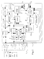
- the line interface shown in the drawings has the function of ensuring the electrical connection between the bus 1 of the network and the protocol manager 2 associated with a communication station.
- Bus 1 is of the two-wire type and has two wires 11 and 12 (DATA +, DATA-).
- the binary states are materialized on the bus by a differential voltage between the two wires, the direction of polarity coding the value of the binary state.
- the interface includes an analog filter 3, two inputs e1 and e2 of which are connected to the bus wires and the two outputs of which s1 and s2 are connected to a shaping circuit 4 (oblique).
- circuit 4 transforms the logic signals from the protocol manager into analog signals suitable for the bus.
- circuit 4 performs the reverse operation.
- the outputs s1 and s2 of the filter 3 are connected to a first comparator 43 whose output Ro is connected to a decision circuit 5.
- the output s1 of the filter 3 is connected to a second comparator 41, the other input of which is connected to a reference voltage.
- the output ERR1 of this comparator 41 is connected to the decision circuit 5.
- the output s2 of the filter is connected to a third comparator 42, the other input of which is connected to the reference voltage.
- the output ERR2 of this comparator 42 is connected to the decision circuit 5.
- the circuit 44 receives the signals from the protocol manager 2 and sends them directly, after shaping, to the wires of the bus.
- the decision circuit 5 continuously analyzes the output state of the three comparators to deduce the operating state (normal mode or degraded mode) and indicate it to the network manager 2.
- the signals leaving comparators 41 and 42 are processed by digital filters 61 and 62 respectively.
- These filters 61 and 62 are identical and are shown in FIG. 6. They consist of 3 flip-flops D 611 to 613 (or 612 to 623) mounted in shift register and a flip-flop JK 616 (or 626). The inputs of this flip-flop receive the signals of two gates ET and NOR each decoding the output signals of flip-flops 611 to 613. The signal of a clock 6 3 is applied to the clock inputs of the flip-flops.
- the principle of these filters is based on the sampling of the signal from the comparator 43 or 42.
- the signal is injected on the first flip-flop 611 whose output signal is sent to the next flip-flop.
- the last three samples at the output of the three flip-flops 611 to 613 are decoded by the "AND” gate 614 and a "NOR" gate 615 which respectively control the inputs J and K of the last flip-flop 616. Switching over the comparator output is only taken into account if it is observed on three successive samples. This switching results in a change of state on the output of flip-flop 616.
- the sampling frequency is adjusted so that there are at least three samples per bit taking into account the clock drifts.
- the initialization of the sampler is done in order to obtain at the output a logic level corresponding to a recessive state (absence of communication on the bus).
- the signals at the output of filters 61 and 62 are sent to counters 71 and 72 respectively.
- Each counter 71 or 72 consists of three D flip-flops 711, 712, 713 receiving on the "Clock" input the output signal of the filter 61 or 62.
- the counter 71 is reset to zero on its input 715 by a reset circuit 73 activated by the input signal arriving on the other counter 72.
- the counter 72 is reset to zero on its input 725 by a circuit reset 74 activated by the input signal arriving on the other counter 71.
- one of the counters 71 or 72 reaches a maximum value (4 for example).
- the overflow pulse will immediately trigger via input 81 the control circuit 8 comprising flip-flops 83 and 82 ensuring the changeover to degraded mode by a level 0.
- Circuit 8 receives the counter outputs 71 and 72, ie the output of the flip-flop 753.
- Each counter 71 or 72 is of the synchronous type and operates on a falling edge of the clock.
- the output of the counter 71 (or 72) is back-coupled by 714 (or 724) and an AND gate 716 (or 726), on resetting all the flip-flops 711 to 713 (or 721 to 723), which allows to limit the count to the desired value (4) with generation of a pulse which is used for the command to store the fault.
- the detection of faults is done using counters 71 and 72, by permanent analysis of the state of outputs of these counters.
- the overflow pulse forces to 1 the output of a storage flip-flop 91 or 92. As long as the fault is present, this output remains at 1
- the transition 0-1 at the end of the circuit command by 13 a reset circuit 75 which resets the flip-flops to zero, during the transition from degraded mode to nominal mode, that is to say at the second pulse of the clock circuit 11 called "watch dog", after disappearance of the fault.
- the counters are reset to zero, not with a resistance-conductor network (creation of a delay) but with the reset circuit 73 or 74 in FIG. 5.
- the input of the reset circuit 73 or 74 is attacked by the filtered output of a comparator 41 or 42. Each falling edge causes the activation of the RESET.
- This circuit 73 or 74 makes it possible to obtain a pulse of sufficient duration for the reset since it is defined by the required hold time on the "Erase" input of the flip-flop D 731 or 741.
- the output signal from comparator 43 is injected into a counter 75 shown in FIG. 4.
- This counter 75 is used to validate the normal state and to detect faults not seen by the counters 71 and 72 (short circuit between the two wires or bus without communication).
- This synchronous type counter consists of two flip-flops D 751 and 752 and a storage flip-flop JK 753 each receiving on the "Clock" input the output signal from comparator 43.
- the last stage constitutes by the flip-flop JK 753 memorizes the passage of a predetermined number of transitions of the signal leaving the comparator. As an indication, this predetermined number is 4.
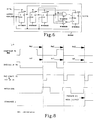
- the counter is reset only periodically by a supervision signal from the so-called "watch dog" clock circuit and injected by the reset on the scales.
- the so-called "watch dog” signal is a train of periodic pulses.
- the stations During the course of the operation without anomaly the stations must enter into communication at least once during the period of the signal called "watch dog". So over the period of the so-called “watch dog” signal, it is checked that the output of the counter 75 has indeed switched several times.
- the minimum number of switches counted by 75 for a message on the bus is at least equal to the minimum number of transitions in a message frame.
- the output signal from flip-flop 753 is sent to a validation circuit 82 (AND gate) also receiving the signal from circuit 11.
- the "watch dog” pulse validates by validation circuit 82 the output signal from the flip-flop JK 753 when reversed.
- An O on output 82 results in normal mode, a 1 in degraded mode.
- the "watch dog” impulse also activates the reset of counter 75 and resets the output of flip-flop 753 once validation has been made.
- This control circuit 8 is constituted by an AND gate 81 which receives the output of the counters 71 and 72 and that of the flip-flop 753.
- the reset circuit 79 enabling the reset signal for the counter 75 and the reset signal for the JK flip-flop 753 to be obtained from the "watch dog" is similar to that of FIG. 5 but without inverting the input signal.
- the output signal is inverted to create the validation command.
- a second inversion provides the delayed reset signal.
- This circuit 93 consists of 4 "NOR" circuits 931, one input of which is connected to the output Q of a flip-flop 91 and the other input of which is connected to the other output of the other flip-flop 91 or 92.
- the state 1-1 of the two flip-flops 91 or 92 would indicate a succession of faults alternately on the wires of the bus - without going back to the normal state. This case is transformed into a succession of states O-1, 1-O (or vice versa) by resetting to zero of a flip-flop D 91 or 92 opposite the counter in overflow.
- the four "NOR” 931 of the decoding circuit 93 decode the output state of the storage flip-flops (91 or 92). As the normal state and the short-circuit are represented by the same pair of "bits” OO, the output of "NOR” must be validated by the command "degraded mode” (done simply by AND 932 gates). A detected short circuit activates output 95 going to protocol manager 2.
- each AND gate 14 goes to an input of an "AND" gate 131 whose other input receives the signal from a comparator 41, 42 or so as to validate or not the output of this gate 131.
- the selection circuit 13 receiving the signals from the AND gates 14 and the comparators makes it possible to communicate on a single wire either on 11 or on 12 depending on the fault detected.
- the combination of the output of these wires is decoded by a set 12 composed of 4 "AND" 121. According to the pair of logic levels, only one output is at level 1, it validates the desired state (manual or automatic). In manual mode, the inhibition input of the comparator outputs is forced. In automatic the control is carried out according to the assembly analysis.
- Figure 7 shows the realization of the interface on a macrocomponent with 32 rockers.
- One of the criteria for choosing the macrocomponent is its small size. However, its use is not essential. In the latter case the system could be improved by increasing the sampling speed in the digital filters and analyzed on a larger number of samples with decision making of the switching operations as a function of a certain percentage of 1 and O.
Claims (8)
- Leitungsschnittstelle für ein Nachrichtenübertragungsnetz, insbesondere in einem Kraftfahrzeug, mit einem Filter (3), dessen Eingang Signale einer Zweifach-Busleitung (1) zugeführt werden und der ein gefiltertes Signal einer Transformationsschaltung (4) zuführt, welche drei Vergleicher (41, 42, 43) aufweist, wobei der erste (43) die gefilterten Signale erhält, der zweite (41) das gefilterte Signal der einen Leitung sowie eine Referenzspannung erhält und der dritte (42) das gefilterte Signal der anderen Leitung sowie eine Referenzspannung erhält, dadurch gekennzeichnet, daß sie Zähler (71, 72) aufweist, denen die Ausgangssignale des zweiten und dritten Vergleichers (41, 42) zugeführt werden, wobei jeder Zähler auf Null gestellt wird durch das Eingangssignal des anderen Zählers, um so an einem Ausgang eine Anzahl von Übergängen zu messen, welche eine vorgegebene Anzahl übersteigt, während der andere Ausgang diese nicht zählt und daß sie einen Zähler (75) aufweist, dem das Signal des ersten Vergleichers (43) zugeführt wird, zur Zählung einer vorgegebenen Anzahl von Übergängen dieses Signals während eines Zeitraums und zur Abgabe eines Fehlersignals, wenn diese Anzahl kleiner ist als die vorgegebene Anzahl und daß sie elektronische Schaltkreise (91, 92, 93, 8, 10) aufweist, um eine Zustandsänderung des Modussignals auszulösen, das der Protokoll-Steuerschaltung zugeführt wird, wenn ein Fehlersignal festgestellt wird.
- Leitungsschnittstelle nach Anspruch 1, dadurch gekennzeichnet, daß die Zähler (71, 72, 75) Synchronzähler sind.
- Leitungsschnittstelle nach einem der vorhergehenden Ansprüche, dadurch gekennzeichnet, daß sie ein numerisches Filter (61 und 62) am Ausgang des zweiten und dritten Vergleichers (41 und 42) aufweist, wobei dieses numerische Filter den Zählern (71, 72) ein gefiltertes Signal zuführt.
- Leitungsschnittstelle nach einem der vorhergehenden Ansprüche, dadurch gekennzeichnet, daß die Signale der Zähler (71, 72), die den zweiten und dritten Vergleichern (41, 42) zugeordnet sind, Speicher-Kippschaltungen (91, 92) zugeführt werden.
- Leitungsschnittstelle nach Anspruch 4, dadurch gekennzeichnet, daß die Ausgangssignale der Speicher-Kippschaltungen (91, 92) einer Fehler-Erkennungs-Schaltung (93) zugeführt werden, die eine NOR-Schaltung (931) enthält.
- Schnittstelle nach einem der vorhergehenden Ansprüche, dadurch gekennzeichnet, daß jedes numerische Filter (61, 62) aus Kippschaltungen (611, 616), einer UND-Schaltung und einer NOR-Schaltung besteht zur Ansteuerung der Eingänge der letzten Kippschaltung.
- Schnittstelle nach einem der vorhergehenden Ansprüche, dadurch gekennzeichnet, daß der dem ersten Vergleicher (43) zugeordnete Zähler (75) eine Kippschaltung (753) aufweist, welche den Durchlauf einer vorgegebenen Anzahl von Übergängen des Ausgangssignals des Vergleichers speichert, wobei ein erneuter Beginn periodisch durch ein von einer Uhrschaltung (11) abgegebenes Signal ausgelöst wird.
- Schnittstelle nach einem der vorhergehenden Ansprüche, dadurch gekennzeichnet, daß sie eine Auswahlschaltung (13) aufweist, die die Signale der Fehler-Erkennungs-Schaltung (93) erhält sowie die Signale der Vergleicher.
Applications Claiming Priority (2)
| Application Number | Priority Date | Filing Date | Title |
|---|---|---|---|
| FR8914770 | 1989-11-10 | ||
| FR8914770A FR2654564B1 (fr) | 1989-11-10 | 1989-11-10 | Interface de ligne pour un reseau de transmission d'informations. |
Publications (2)
| Publication Number | Publication Date |
|---|---|
| EP0427638A1 EP0427638A1 (de) | 1991-05-15 |
| EP0427638B1 true EP0427638B1 (de) | 1995-01-18 |
Family
ID=9387279
Family Applications (1)
| Application Number | Title | Priority Date | Filing Date |
|---|---|---|---|
| EP90403186A Expired - Lifetime EP0427638B1 (de) | 1989-11-10 | 1990-11-09 | Leitungschnittstelle für ein Nachrichtenübertragungsnetz |
Country Status (5)
| Country | Link |
|---|---|
| US (1) | US5267251A (de) |
| EP (1) | EP0427638B1 (de) |
| DE (1) | DE69016169T2 (de) |
| ES (1) | ES2067001T3 (de) |
| FR (1) | FR2654564B1 (de) |
Families Citing this family (25)
| Publication number | Priority date | Publication date | Assignee | Title |
|---|---|---|---|---|
| FR2679723B1 (fr) * | 1991-07-23 | 1994-12-30 | Siemens Automotive Sa | Procede de transmission de donnees numeriques emises sous forme de trames de signaux differentiels. |
| US5555438A (en) * | 1991-07-24 | 1996-09-10 | Allen-Bradley Company, Inc. | Method for synchronously transferring serial data to and from an input/output (I/O) module with true and complement error detection coding |
| FR2680294B1 (fr) * | 1991-08-07 | 1993-11-19 | Peugeot | Dispositif de transmission d'informations en differentiel entre au moins deux organes d'un vehicule automobile. |
| JP3133490B2 (ja) * | 1991-08-27 | 2001-02-05 | 古河電気工業株式会社 | 多重伝送装置 |
| JP2728155B2 (ja) * | 1991-12-19 | 1998-03-18 | 三菱電機株式会社 | 通信制御装置 |
| IT1252576B (it) * | 1991-12-20 | 1995-06-19 | Italtel Spa | Struttura di rete ottica passiva con elevata insensibilita' ai guasti |
| FR2689710A1 (fr) * | 1992-04-02 | 1993-10-08 | Renault | Perfectionnements aux dispositifs de diagnostic dans une interface de ligne pour un réseau de transmission d'informations. |
| FR2695780B1 (fr) * | 1992-09-15 | 1994-11-25 | Siemens Automotive Sa | Procédé de détection d'un court-circuit entre les lignes d'un bus transmettant des données numériques sous forme de signaux différentiels de tension. |
| DE4307794C2 (de) * | 1993-03-12 | 1995-02-16 | Daimler Benz Ag | Einrichtung zur Überwachung symmetrischer Zweidraht-Busleitungen und -Busschnittstellen |
| JPH07177202A (ja) * | 1993-12-21 | 1995-07-14 | Mitsubishi Electric Corp | 通信制御装置 |
| DE4403899B4 (de) * | 1994-02-08 | 2007-12-13 | Robert Bosch Gmbh | Vorrichtung zur seriellen Übertragung von Daten zwischen mindestens zwei Stationen |
| DE19509133C2 (de) * | 1994-04-11 | 2003-07-17 | Daimler Chrysler Ag | Anordnung zur Überwachung von Zweidraht-Busleitungen |
| DE4421083C2 (de) * | 1994-06-16 | 1996-04-11 | Volkswagen Ag | Verfahren zur Überwachung einer seriellen Übertragung von digitalen Daten auf einer Ein-Draht-Multiplexverbindung zwischen untereinander kommunizierenden Signalverarbeitungsgeräten |
| US5758065A (en) * | 1995-11-30 | 1998-05-26 | Ncr Corporation | System and method of establishing error precedence in a computer system |
| DE19611944C2 (de) * | 1996-03-26 | 2003-03-27 | Daimler Chrysler Ag | Integrierter Schaltkreis zur Kopplung eines mikrokontrollierten Steuergerätes an einen Zweidraht-Bus |
| ID22443A (id) | 1996-11-15 | 1999-10-14 | Montelll Technology Co Bv | Metallosena heterosiklik dan polimerisasi katalis |
| DE19826388B4 (de) * | 1998-06-12 | 2007-01-11 | Sgs-Thomson Microelectronics Gmbh | Fehlerverarbeitungsschaltung für eine Empfangsstelle eines Datenübertragungssystems |
| JP3207392B2 (ja) * | 1998-09-11 | 2001-09-10 | 沖電気工業株式会社 | データ格納制御回路 |
| US7089437B2 (en) * | 2001-06-18 | 2006-08-08 | Texas Instruments Incorporated | Apparatus for determining power consumed by a bus of a digital signal processor using counted number of logic state transitions on bus |
| DE50115035D1 (de) * | 2001-10-31 | 2009-09-24 | Infineon Technologies Ag | Bus-Interface |
| ITTO20030944A1 (it) * | 2003-11-26 | 2005-05-27 | Urmet Telecomunicazioni S P A | Sistema di monitoraggio di linee di comunicazione e telesegnalazione. |
| US8429393B1 (en) * | 2004-09-30 | 2013-04-23 | Rockwell Automation Technologies, Inc. | Method for obscuring a control device's network presence by dynamically changing the device's network addresses using a cryptography-based pattern |
| US8059595B2 (en) * | 2007-04-06 | 2011-11-15 | Qualcomm Incorporated | Handoff of data attachment point |
| DE102017212543A1 (de) * | 2017-07-21 | 2019-01-24 | Robert Bosch Gmbh | Sende-/Empfangseinrichtung für ein Bussystem und Verfahren zur Reduktion von leitungsgebundenen Emissionen |
| DE102017212544A1 (de) * | 2017-07-21 | 2019-01-24 | Robert Bosch Gmbh | Sende-/Empfangseinrichtung für ein CAN Bussystem und Verfahren zur Erkennung eines Kurzschlusses mit einer CAN Sende-/Empfangseinrichtung |
Family Cites Families (5)
| Publication number | Priority date | Publication date | Assignee | Title |
|---|---|---|---|---|
| US4551671A (en) * | 1983-06-23 | 1985-11-05 | International Business Machines Corp. | Terminal disconnect and media wire fault detect mechanism |
| US4545055A (en) * | 1983-07-20 | 1985-10-01 | Loral Corporation | Error analyzer for data communicated by bus protocol |
| DE3342763C2 (de) * | 1983-11-25 | 1985-11-28 | Siemens AG, 1000 Berlin und 8000 München | Schaltungsanordnung zum Überwachen von symmetrischen Leitungen |
| US4782300A (en) * | 1986-03-03 | 1988-11-01 | International Business Machines Corporation | Differential transceiver with line integrity detection |
| FR2627036B1 (fr) * | 1988-02-10 | 1990-07-27 | Peugeot | Interface de raccordement d'une partie de reception d'informations d'une station dans un systeme de transmission d'informations en differentiel, par deux fils de transmission, notamment dans un vehicule automobile |
-
1989
- 1989-11-10 FR FR8914770A patent/FR2654564B1/fr not_active Expired - Lifetime
-
1990
- 1990-11-09 DE DE69016169T patent/DE69016169T2/de not_active Expired - Lifetime
- 1990-11-09 ES ES90403186T patent/ES2067001T3/es not_active Expired - Lifetime
- 1990-11-09 EP EP90403186A patent/EP0427638B1/de not_active Expired - Lifetime
- 1990-11-13 US US07/611,696 patent/US5267251A/en not_active Expired - Lifetime
Also Published As
| Publication number | Publication date |
|---|---|
| FR2654564A1 (fr) | 1991-05-17 |
| EP0427638A1 (de) | 1991-05-15 |
| DE69016169T2 (de) | 1995-08-10 |
| US5267251A (en) | 1993-11-30 |
| ES2067001T3 (es) | 1995-03-16 |
| DE69016169D1 (de) | 1995-03-02 |
| FR2654564B1 (fr) | 1992-01-17 |
Similar Documents
| Publication | Publication Date | Title |
|---|---|---|
| EP0427638B1 (de) | Leitungschnittstelle für ein Nachrichtenübertragungsnetz | |
| EP0014152B1 (de) | Operator für Datenpaketvermittlungsnetz | |
| EP0064888A1 (de) | Verfahren und Einrichtung zum Feststellen von Zusammenstössen und zum Steuern von Sicherheitsanlagen | |
| EP0002415B1 (de) | Verfahren und Einrichtung zum Zählen der Übertragungsfehler in einer digitalen Richtfunkstrecke | |
| EP0335799B1 (de) | Elektronische Methoden und Schaltungen zur drahtgebundenen Fernabfrage von elektrischen Empfänger | |
| FR2689660A1 (fr) | Procédé pour contrôler des lignes de bus et des interfaces de bus bifilaires symétriques et dispositif pour la mise en Óoeuvre du procédé. | |
| EP0527076B1 (de) | Differentielle Datenübertragung zwischen mindesten zwei elektronischen Bauteilen in einem Kraftfahrzeug | |
| EP0068977B1 (de) | Verfahren zur Nachrichtenübertragung zwischen selbständigen Sende- und Empfangsmodulen welche unabhängige Taktgeber und interne Synchronisationseinrichtungen besitzen | |
| FR2679723A1 (fr) | Procede de transmission de donnees numeriques emises sous forme de trames de signaux differentiels. | |
| EP0726666B1 (de) | Schnittstellenvorrichtung zwischen Haus-Netzwerkübertragungsmedien | |
| FR2643481A1 (fr) | Procede et dispositif de transmission d'informations entre stations d'un reseau de communication, notamment pour vehicule automobile | |
| FR2859853A1 (fr) | Procede de detection automatique du debit d'un reseau, notamment de type bus can, et de configuration au debit detecte, dispositif correspondant | |
| CA1240385A (fr) | Circuit de decodage du preambule renforce a balayage rapide d'un recepteur de bord mls | |
| EP0006798A1 (de) | Digitales Kommunikationssystem mit hohem Datenfluss in einem Maschennetzwerk | |
| EP0110481A1 (de) | System zur Identifizierung lokaler Stationen durch eine zentrale Abfragestation | |
| FR2710804A1 (fr) | Dispositif numérique de connexion d'une pluralité de stations de travail sur un réseau local en anneau. | |
| EP0404630B1 (de) | Vorrichtung zum Empfang von über zwei kapazitiv gekoppelte Leitungen durchgehenden Informationen, insbesondere für Kraftfahrzeuge | |
| EP0905946B1 (de) | Reglung der Abtastung von Biphasensignalen | |
| EP0363231B1 (de) | Verfahren zur Übertragung von Nachrichten mittels einer bidirektionalen Strecke, und Gerät zu dessen Durchführung | |
| FR2726675A1 (fr) | Systeme de transmission d'informations notamment pour vehicule automobile | |
| CA2466666A1 (fr) | Systeme de commande a architecture distribuee pour convertisseurs statiques de puissance | |
| EP0373067A1 (de) | Sende-Empfangssynchronisationsvorrichtung einer Station eines Kommunikationsnetzes, insbesondere für ein Kraftfahrzeug | |
| EP0338881B1 (de) | Verfahren und Vorrichtung zur Signalrekonfiguration in einem differentiellen Nachrichtenübertragungsnetzwerk, insbesondere in einem Kraftfahrzeug | |
| CA2019774C (fr) | Dispositif de detection dans un signal binaire d'une signalisation formee nominalement d'une serie continue d'elements binaires de meme valeur | |
| FR2674395A1 (fr) | Procede de transmission de donnes numeriques emises sous forme de trames de signaux differentiels. |
Legal Events
| Date | Code | Title | Description |
|---|---|---|---|
| PUAI | Public reference made under article 153(3) epc to a published international application that has entered the european phase |
Free format text: ORIGINAL CODE: 0009012 |
|
| AK | Designated contracting states |
Kind code of ref document: A1 Designated state(s): DE ES GB IT |
|
| 17P | Request for examination filed |
Effective date: 19911025 |
|
| 17Q | First examination report despatched |
Effective date: 19931208 |
|
| GRAA | (expected) grant |
Free format text: ORIGINAL CODE: 0009210 |
|
| AK | Designated contracting states |
Kind code of ref document: B1 Designated state(s): DE ES GB IT |
|
| ITF | It: translation for a ep patent filed |
Owner name: JACOBACCI & PERANI S.P.A. |
|
| GBT | Gb: translation of ep patent filed (gb section 77(6)(a)/1977) |
Effective date: 19950123 |
|
| REF | Corresponds to: |
Ref document number: 69016169 Country of ref document: DE Date of ref document: 19950302 |
|
| REG | Reference to a national code |
Ref country code: ES Ref legal event code: FG2A Ref document number: 2067001 Country of ref document: ES Kind code of ref document: T3 |
|
| PLBE | No opposition filed within time limit |
Free format text: ORIGINAL CODE: 0009261 |
|
| STAA | Information on the status of an ep patent application or granted ep patent |
Free format text: STATUS: NO OPPOSITION FILED WITHIN TIME LIMIT |
|
| 26N | No opposition filed | ||
| REG | Reference to a national code |
Ref country code: GB Ref legal event code: IF02 |
|
| PGFP | Annual fee paid to national office [announced via postgrant information from national office to epo] |
Ref country code: ES Payment date: 20091123 Year of fee payment: 20 Ref country code: DE Payment date: 20091120 Year of fee payment: 20 |
|
| PGFP | Annual fee paid to national office [announced via postgrant information from national office to epo] |
Ref country code: GB Payment date: 20091119 Year of fee payment: 20 Ref country code: IT Payment date: 20091126 Year of fee payment: 20 |
|
| REG | Reference to a national code |
Ref country code: GB Ref legal event code: PE20 Expiry date: 20101108 |
|
| REG | Reference to a national code |
Ref country code: ES Ref legal event code: FD2A Effective date: 20110228 |
|
| PG25 | Lapsed in a contracting state [announced via postgrant information from national office to epo] |
Ref country code: GB Free format text: LAPSE BECAUSE OF EXPIRATION OF PROTECTION Effective date: 20101108 |
|
| PG25 | Lapsed in a contracting state [announced via postgrant information from national office to epo] |
Ref country code: ES Free format text: LAPSE BECAUSE OF EXPIRATION OF PROTECTION Effective date: 20101110 |
|
| PG25 | Lapsed in a contracting state [announced via postgrant information from national office to epo] |
Ref country code: DE Free format text: LAPSE BECAUSE OF EXPIRATION OF PROTECTION Effective date: 20101109 |