EP0426977A2 - Tour à broche verticale - Google Patents
Tour à broche verticale Download PDFInfo
- Publication number
- EP0426977A2 EP0426977A2 EP90117718A EP90117718A EP0426977A2 EP 0426977 A2 EP0426977 A2 EP 0426977A2 EP 90117718 A EP90117718 A EP 90117718A EP 90117718 A EP90117718 A EP 90117718A EP 0426977 A2 EP0426977 A2 EP 0426977A2
- Authority
- EP
- European Patent Office
- Prior art keywords
- longitudinal
- machine stand
- guides
- slide
- workpiece spindle
- Prior art date
- Legal status (The legal status is an assumption and is not a legal conclusion. Google has not performed a legal analysis and makes no representation as to the accuracy of the status listed.)
- Withdrawn
Links
Images


Classifications
-
- B—PERFORMING OPERATIONS; TRANSPORTING
- B23—MACHINE TOOLS; METAL-WORKING NOT OTHERWISE PROVIDED FOR
- B23B—TURNING; BORING
- B23B3/00—General-purpose turning-machines or devices, e.g. centre lathes with feed rod and lead screw; Sets of turning-machines
- B23B3/16—Turret lathes for turning individually-chucked workpieces
- B23B3/167—Turret lathes for turning individually-chucked workpieces lathe with two or more toolslides carrying turrets
- B23B3/168—Arrangements for performing other machining operations, e.g. milling, drilling
-
- B—PERFORMING OPERATIONS; TRANSPORTING
- B23—MACHINE TOOLS; METAL-WORKING NOT OTHERWISE PROVIDED FOR
- B23Q—DETAILS, COMPONENTS, OR ACCESSORIES FOR MACHINE TOOLS, e.g. ARRANGEMENTS FOR COPYING OR CONTROLLING; MACHINE TOOLS IN GENERAL CHARACTERISED BY THE CONSTRUCTION OF PARTICULAR DETAILS OR COMPONENTS; COMBINATIONS OR ASSOCIATIONS OF METAL-WORKING MACHINES, NOT DIRECTED TO A PARTICULAR RESULT
- B23Q1/00—Members which are comprised in the general build-up of a form of machine, particularly relatively large fixed members
- B23Q1/01—Frames, beds, pillars or like members; Arrangement of ways
Definitions
- the invention relates to a lathe with a vertically arranged workpiece spindle for rotatably holding a workpiece to be machined, with a vertically extending machine stand of approximately square cross-section and with vertical longitudinal guides for at least two longitudinal slides arranged on at least two adjacent vertical surfaces of the machine stand, which in turn have horizontal transverse guides for cross slides wear, the one carriage preferably carries rotatingly driven, radial tools.
- the workpiece spindle axis lies at the intersection of the extended axis of rotation of the tools of the star turret with the parallel to the direction of feed through the switching axis of the drum turret.
- the tools of both tool carriers move further apart, the smaller the angle that their plane guideways form to each other, and the introduction of force into the guideways and the lever arms to the force application point become less favorable. Therefore, in the prior art, the plan guidance of one tool carrier is inclined to the plan guidance of the other by an angle that is greater than 90 °. However, this limits the processing options. No further feed movement between tool and workpiece can be realized.
- the asymmetrical structure also does not allow another workpiece spindle to be assigned to the same machine stand.
- the invention has for its object to improve the processing options and to increase the variety of machine configurations using the same modules.
- the right-angled arrangement of the transverse guideways enables the workpiece to be moved transversely to the tool carrier with radially directed tools, so that a workpiece can be machined on three axes with rotatingly driven tools.
- the same feed movement also serves to bring the workpiece close to the second tool carrier, so that there are no disadvantages for the introduction of force into the guideways and the lever arms from the right-angled arrangement of the guideways.
- the movement of the workpiece spindle allows the workpiece to be moved so far towards the tool carrier with the internal machining tools that even when drilling in the center of the workpiece
- the cross slide does not protrude beyond the cross slide guides, but rests on the guideways along its entire length.
- four tools can be used simultaneously with fixed tools of both tool carriers on the outer circumference of a workpiece held in the chuck of the workpiece spindle.
- a further workpiece spindle can be arranged on the side opposite the first workpiece spindle in relation to the tool carrier. If a switchable tool holder is used, it is even possible to work with the same tools on workpieces held by these additional workpiece spindles.
- the separation of machine stand and slide bracket into independent units allows any combination of these modules. They can easily be adjusted to each other on a base.
- the individual assemblies can now be combined to form a production system with up to four workpiece spindles and four tool carriers, which is also only possible through the proposed arrangement of the transverse guideways.
- the workpiece spindles are arranged in the quadrants diagonally opposite the machine stand, which result from the imaginary extension of the vertical machine stand surfaces.
- Tools can be arranged on the cross slide in such a way that some can be used for machining a workpiece in a first workpiece spindle and others for machining a workpiece in a spindle opposite to the cross slide.
- the workpiece spindle on which no machining is currently taking place can then be loaded. Even with four workpiece spindles, each can work with the two adjacent cross slides. If revolvers are used as tool carriers the same tools can be used in the switching position of the tool turret, which is offset by 180 °, on the other workpiece spindle.
- Fig. 1 shows a single-spindle version of a vertical lathe in plan view.
- the machine stand 1 which is fastened to a base (not shown), has two longitudinal guides 2 on each of the four vertical surfaces.
- the longitudinal guides 2 on two adjacent surfaces carry longitudinal slides 3, 4, which are held on the longitudinal guides 2 with undergrip strips 5.
- the longitudinal slide 3, 4 are moved up and down by threaded spindles 6.
- Both longitudinal slides 3, 4 carry transverse guides 7, 8 over their entire width, on which cross slides 9, 10 are slidably held.
- a drum turret 11 is fastened on one face slide 10 and has tool holders 12 for boring bars 14 and turning tools 13.
- the second cross slide 9 carries a star turret 15 with rotatingly driven tools, such as Twist drill 16, end mill 17 and single-lip drill 18. It can also accommodate turning tools 19 for face and long turning operations.
- the extensions of the occupied vertical surfaces 20, 21 of the machine stand 1 form an axis cross in plan view with four quadrants, one of which is occupied by the machine stand 1, two further by a tool holder 11, 15 and the last by the workpiece spindle 22.
- the arrangement of the assemblies essentially in their own quadrants results, according to the invention, in the collision-free, favorable machining conditions and the expandability of the lathe.
- the workpiece spindle 22 is mounted in a workpiece spindle slide 23 which is displaceable on guideways 24 of a bracket 25.
- the arrangement of the workpiece spindle 22 on the bracket 25 is shown in more detail in FIG. 2.
- the workpiece spindle 22 carries a chuck 26 and is surrounded by a spindle motor 27.
- a clamping cylinder 28 for actuating the chuck 26 is flanged to the workpiece spindle 22.
- a hollow shaft encoder 29 for controlling the spindle motor 27 can be integrated in the spindle motor 27.
- the spindle motor 27 is connected via a cable guide 30 to a power source so that it can move freely in the direction of the guideway.
- the displacement of the workpiece spindle slide 23 and thus the workpiece spindle 22 causes a threaded spindle 31 which is non-rotatably fastened to the workpiece spindle slide 23 with a pressure sleeve 32.
- the threaded spindle 31 is in engagement with a spindle nut 33 which is driven by a feed motor 34.
- the spindle nut 33 can be flanged to the rotor of the feed motor 34, with the threaded spindle 31 then penetrating the feed motor 34. In this way, a centric force application of the threaded spindle 31 to the workpiece spindle slide 23 is possible without additional gear elements.
- the guideways 24 for the workpiece spindle slide 23 on the bracket 25 are covered by telescopic plates 35.
- the workpiece spindle slide 23 is adjustable by means of wedge strips 36.
- the counter bar 37 is provided with a plurality of hydraulically actuated pistons 38 which clamp the slide on the guideways 24 in any feed position.
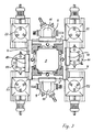
- Fig. 3 shows the highest stage of the vertical lathe with four workpiece spindles 22.
- Two workpiece spindles 22 are arranged symmetrically to each other.
- On the square machine stand 1 two cross slides 4, 10 for drum turret 11 and two cross slides 3, 9 for star turret 15 are guided on opposite end faces. All workpiece spindles 22 are displaceable transversely to the feed directions of the cross slides 3, 9 for the star turret 15 and in the direction of the plane feed of the cross slides 4, 10 of the drum turret 11.
- the drum turrets 11 preferably carry the axial machining tools and the long turning tools, while the star turrets 15 hold the radial tools and the plunge turning tools.
- the tools can e.g. as a linear tool holder can also be attached directly to the respective cross slide.
- each tool holder can work simultaneously with one of the workpiece spindles, with all four spindles being machined at the same time.
- two tool carriers can also act jointly on a workpiece of a workpiece spindle, two workpiece spindles then being free for loading and unloading.
- FIG. 4 shows a front view of the arrangement of the units on a base 40.
- two brackets 42 are screwed to the base 40.
- the workpiece spindle slides 43 have guide webs 44, 45 of different heights, which are held in the counter guides of the console 42 by guide strips 46. This results in an inclination toward the machine stand 1 for the guideway covers 47, 48.
- the machine stand 1 has an opening 49 into which a chip conveyor 50 is inserted.
- the space between the chip conveyor 50 and the guideway covers 47, 48 is closed by chip guide plates 51.
- the two drum revolvers 11 with their longitudinal and cross slide 4, 10 and the star revolver 15 on its longitudinal and cross slide 3, 9 can be seen on the machine stand 1.
- the longitudinal slide 3, 4 are moved by threaded spindles 6, which are driven by feed motors 52.
- the work space is sealed off from the surroundings by a work space cover 53.
Landscapes
- Engineering & Computer Science (AREA)
- Mechanical Engineering (AREA)
- Turning (AREA)
Applications Claiming Priority (2)
| Application Number | Priority Date | Filing Date | Title |
|---|---|---|---|
| DE3937330 | 1989-11-09 | ||
| DE19893937330 DE3937330A1 (de) | 1989-11-09 | 1989-11-09 | Drehmaschine mit vertikaler werkstueckspindel |
Publications (2)
| Publication Number | Publication Date |
|---|---|
| EP0426977A2 true EP0426977A2 (fr) | 1991-05-15 |
| EP0426977A3 EP0426977A3 (en) | 1991-11-21 |
Family
ID=6393203
Family Applications (1)
| Application Number | Title | Priority Date | Filing Date |
|---|---|---|---|
| EP19900117718 Withdrawn EP0426977A3 (en) | 1989-11-09 | 1990-09-14 | Vertical spindle lathe |
Country Status (2)
| Country | Link |
|---|---|
| EP (1) | EP0426977A3 (fr) |
| DE (1) | DE3937330A1 (fr) |
Cited By (2)
| Publication number | Priority date | Publication date | Assignee | Title |
|---|---|---|---|---|
| EP0953403A2 (fr) * | 1998-04-27 | 1999-11-03 | ILG GmbH | Machine-outil |
| EP1216789A2 (fr) * | 2000-12-22 | 2002-06-26 | Hüller Hille GmbH | Tour à broche verticale |
Families Citing this family (2)
| Publication number | Priority date | Publication date | Assignee | Title |
|---|---|---|---|---|
| DE4229423C3 (de) * | 1992-09-03 | 1998-10-01 | Index Werke Kg Hahn & Tessky | Drehmaschine |
| DE4322744C2 (de) † | 1993-07-08 | 1998-08-27 | Baumueller Nuernberg Gmbh | Elektrisches Antriebssystem und Positionierverfahren zur synchronen Verstellung mehrerer dreh- und/oder verschwenkbarer Funktionsteile in Geräten und Maschinen, Antriebsanordnung mit einem Winkellagegeber und Druckmaschine |
Citations (5)
| Publication number | Priority date | Publication date | Assignee | Title |
|---|---|---|---|---|
| DE863434C (de) * | 1950-04-23 | 1953-01-19 | Diedesheim G M B H Maschf | Maschine zur gleichzeitigen Drehbearbeitung eines Werkstueckes mittels mehrerer gesondert angetriebener Werkzeuge |
| DE1552393B1 (de) * | 1966-10-31 | 1969-10-16 | Froriep Gmbh Maschf | Schwerwerkzeugmaschine |
| DE2160291A1 (de) * | 1971-12-04 | 1973-06-20 | Weisser Soehne J G | Bauteilsatz zum zusammensetzen von drehmaschinen |
| US3813745A (en) * | 1971-09-16 | 1974-06-04 | Monarch Machine Tool Co | Dual turret lathe |
| SU1079364A1 (ru) * | 1982-09-29 | 1984-03-15 | Предприятие П/Я Р-6930 | Токарный обрабатывающий центр |
Family Cites Families (5)
| Publication number | Priority date | Publication date | Assignee | Title |
|---|---|---|---|---|
| DE2104905A1 (de) * | 1971-02-03 | 1972-08-17 | Gildemeister Werkzeugmasch | Numerisch gesteuerte Drehmaschine mit Kreuzschlitten |
| SE388554B (sv) * | 1973-06-06 | 1976-10-11 | Smt Machine Co Ab | Svarv |
| JPS52108588A (en) * | 1976-03-10 | 1977-09-12 | Okuma Mach Works Ltd | Value control lathe |
| DE3333467A1 (de) * | 1983-09-16 | 1984-07-12 | Lieber, Werkzeugmaschinenfabrik, Inh. Elfriede Lieber, 4990 Lübbecke | Verbundbett-konstruktion fuer steilbett drehmaschinen |
| DE3803219A1 (de) * | 1988-02-04 | 1989-08-31 | Gildemeister Ag | Numerisch gesteuerte bearbeitungsmaschine mit zwei werkstueckspindeleinheiten |
-
1989
- 1989-11-09 DE DE19893937330 patent/DE3937330A1/de not_active Withdrawn
-
1990
- 1990-09-14 EP EP19900117718 patent/EP0426977A3/de not_active Withdrawn
Patent Citations (5)
| Publication number | Priority date | Publication date | Assignee | Title |
|---|---|---|---|---|
| DE863434C (de) * | 1950-04-23 | 1953-01-19 | Diedesheim G M B H Maschf | Maschine zur gleichzeitigen Drehbearbeitung eines Werkstueckes mittels mehrerer gesondert angetriebener Werkzeuge |
| DE1552393B1 (de) * | 1966-10-31 | 1969-10-16 | Froriep Gmbh Maschf | Schwerwerkzeugmaschine |
| US3813745A (en) * | 1971-09-16 | 1974-06-04 | Monarch Machine Tool Co | Dual turret lathe |
| DE2160291A1 (de) * | 1971-12-04 | 1973-06-20 | Weisser Soehne J G | Bauteilsatz zum zusammensetzen von drehmaschinen |
| SU1079364A1 (ru) * | 1982-09-29 | 1984-03-15 | Предприятие П/Я Р-6930 | Токарный обрабатывающий центр |
Non-Patent Citations (1)
| Title |
|---|
| SOVIET INVENTIONS ILLUSTRATED Sektion Mechanik, Woche 8509, 10. April 1985, Abstrakt Nr. 054321, Derwent Publications Ltd, London, GB; & SU - A - 1079364 (FOLKIN VYA) 15.03.1984 * |
Cited By (4)
| Publication number | Priority date | Publication date | Assignee | Title |
|---|---|---|---|---|
| EP0953403A2 (fr) * | 1998-04-27 | 1999-11-03 | ILG GmbH | Machine-outil |
| EP0953403A3 (fr) * | 1998-04-27 | 2001-06-13 | ILG GmbH | Machine-outil |
| EP1216789A2 (fr) * | 2000-12-22 | 2002-06-26 | Hüller Hille GmbH | Tour à broche verticale |
| EP1216789A3 (fr) * | 2000-12-22 | 2005-01-19 | Cross Hüller GmbH | Tour à broche verticale |
Also Published As
| Publication number | Publication date |
|---|---|
| DE3937330A1 (de) | 1991-05-16 |
| EP0426977A3 (en) | 1991-11-21 |
Similar Documents
| Publication | Publication Date | Title |
|---|---|---|
| EP1834719B1 (fr) | Machine-outil et procédé destiné au traitement par enlèvement de copeaux de pièces usinées, en particulier de pièces usinées métalliques | |
| DE3502328C2 (fr) | ||
| DE19918082B4 (de) | Universal-Werkzeugmaschine | |
| DE3427245C2 (de) | Werkzeugmaschine | |
| CH629407A5 (de) | Werkzeugmaschine. | |
| WO1993007981A1 (fr) | Tour | |
| CH665986A5 (de) | Werkzeugmaschine fuer mehrfache bearbeitung von oberflaechen. | |
| EP0882548A2 (fr) | CNC centres de fournage et de fraisage | |
| DE2739534C2 (de) | Werkzeugwechselvorrichtung | |
| DE3420531C2 (de) | Drehautomat | |
| DE1652728B2 (de) | Kurvenlos programmgesteuerter vierspindel-drehautomat mit horizontal gelagerter spindeltrommel | |
| EP0995539A2 (fr) | Dispositif d'usinage de pièces | |
| DE19919645A1 (de) | Werkzeugmaschine mit Werkzeugspindel und Revolverkopf | |
| DE19904860C2 (de) | Vertikaldrehmaschine | |
| DE3803219C2 (fr) | ||
| EP0834379A2 (fr) | Tour | |
| DE19911156C2 (de) | Drehmaschine zur Bearbeitung von wellenförmigen Werkstücken | |
| DE3826985C1 (fr) | ||
| EP0426977A2 (fr) | Tour à broche verticale | |
| DE102015121925A1 (de) | Werkzeugmaschine | |
| DE19652460C1 (de) | Werkzeugmaschine mit mehreren Spindeln | |
| DE3530982A1 (de) | Zweispindlige, numerisch gesteuerte drehmaschine | |
| DE10139296B4 (de) | Spannvorrichtung für mehrseitig zu bearbeitende Werkstücke | |
| EP0410044B1 (fr) | Tour avec trois broches porte-pièce | |
| DE19504370A1 (de) | Mehrspindeldrehmaschine |
Legal Events
| Date | Code | Title | Description |
|---|---|---|---|
| PUAI | Public reference made under article 153(3) epc to a published international application that has entered the european phase |
Free format text: ORIGINAL CODE: 0009012 |
|
| AK | Designated contracting states |
Kind code of ref document: A2 Designated state(s): AT FR GB IT |
|
| PUAL | Search report despatched |
Free format text: ORIGINAL CODE: 0009013 |
|
| AK | Designated contracting states |
Kind code of ref document: A3 Designated state(s): AT FR GB IT |
|
| 17P | Request for examination filed |
Effective date: 19911218 |
|
| 17Q | First examination report despatched |
Effective date: 19930208 |
|
| STAA | Information on the status of an ep patent application or granted ep patent |
Free format text: STATUS: THE APPLICATION IS DEEMED TO BE WITHDRAWN |
|
| 18D | Application deemed to be withdrawn |
Effective date: 19930608 |