EP0426121B1 - Process for the production of silicon carbide abrasive-water-jet nozzle - Google Patents
Process for the production of silicon carbide abrasive-water-jet nozzle Download PDFInfo
- Publication number
- EP0426121B1 EP0426121B1 EP90120818A EP90120818A EP0426121B1 EP 0426121 B1 EP0426121 B1 EP 0426121B1 EP 90120818 A EP90120818 A EP 90120818A EP 90120818 A EP90120818 A EP 90120818A EP 0426121 B1 EP0426121 B1 EP 0426121B1
- Authority
- EP
- European Patent Office
- Prior art keywords
- silicon carbide
- graphite structure
- water
- process according
- graphite
- Prior art date
- Legal status (The legal status is an assumption and is not a legal conclusion. Google has not performed a legal analysis and makes no representation as to the accuracy of the status listed.)
- Expired - Lifetime
Links
Images
Classifications
-
- C—CHEMISTRY; METALLURGY
- C04—CEMENTS; CONCRETE; ARTIFICIAL STONE; CERAMICS; REFRACTORIES
- C04B—LIME, MAGNESIA; SLAG; CEMENTS; COMPOSITIONS THEREOF, e.g. MORTARS, CONCRETE OR LIKE BUILDING MATERIALS; ARTIFICIAL STONE; CERAMICS; REFRACTORIES; TREATMENT OF NATURAL STONE
- C04B35/00—Shaped ceramic products characterised by their composition; Ceramics compositions; Processing powders of inorganic compounds preparatory to the manufacturing of ceramic products
- C04B35/515—Shaped ceramic products characterised by their composition; Ceramics compositions; Processing powders of inorganic compounds preparatory to the manufacturing of ceramic products based on non-oxide ceramics
- C04B35/56—Shaped ceramic products characterised by their composition; Ceramics compositions; Processing powders of inorganic compounds preparatory to the manufacturing of ceramic products based on non-oxide ceramics based on carbides or oxycarbides
- C04B35/565—Shaped ceramic products characterised by their composition; Ceramics compositions; Processing powders of inorganic compounds preparatory to the manufacturing of ceramic products based on non-oxide ceramics based on carbides or oxycarbides based on silicon carbide
-
- B—PERFORMING OPERATIONS; TRANSPORTING
- B24—GRINDING; POLISHING
- B24C—ABRASIVE OR RELATED BLASTING WITH PARTICULATE MATERIAL
- B24C5/00—Devices or accessories for generating abrasive blasts
- B24C5/02—Blast guns, e.g. for generating high velocity abrasive fluid jets for cutting materials
- B24C5/04—Nozzles therefor
-
- C—CHEMISTRY; METALLURGY
- C01—INORGANIC CHEMISTRY
- C01B—NON-METALLIC ELEMENTS; COMPOUNDS THEREOF; METALLOIDS OR COMPOUNDS THEREOF NOT COVERED BY SUBCLASS C01C
- C01B32/00—Carbon; Compounds thereof
- C01B32/90—Carbides
- C01B32/914—Carbides of single elements
- C01B32/956—Silicon carbide
-
- Y—GENERAL TAGGING OF NEW TECHNOLOGICAL DEVELOPMENTS; GENERAL TAGGING OF CROSS-SECTIONAL TECHNOLOGIES SPANNING OVER SEVERAL SECTIONS OF THE IPC; TECHNICAL SUBJECTS COVERED BY FORMER USPC CROSS-REFERENCE ART COLLECTIONS [XRACs] AND DIGESTS
- Y10—TECHNICAL SUBJECTS COVERED BY FORMER USPC
- Y10T—TECHNICAL SUBJECTS COVERED BY FORMER US CLASSIFICATION
- Y10T29/00—Metal working
- Y10T29/49—Method of mechanical manufacture
- Y10T29/49428—Gas and water specific plumbing component making
- Y10T29/49432—Nozzle making
Definitions
- the present invention relates to a process for producing a silicon carbide abrasive-water-jet nozzle for working articles with an abrasive-water-jet propelled therethrough, the water jet of the abrasive type containing particles of abrasives such as garnet and alumina admixed therein.
- a water-jet working or machining apparatus operates to eject water under high pressure through a nozzle of small throat diameter thereby to render the water into a jet of supersonic velocity and to direct this jet against a workpiece material to work the same.
- abrasive type water jets containing particles of abrasives such as alumina and garnet are also being developed.
- the inner surface of the nozzle constituting the flow path and orifice for discharging the water jet is subject to severe abrasion and wear. Accordingly, materials such as cemented carbide alloys, refractory hard metals, and alumina ceramics are ordinarily being used for these nozzles. There are also nozzles made of sintered skeletons of cubic boron nitride as disclosed, for example, in Japanese Utility Model Appln. Laid-Open No. 63-50700 published April 6, 1988. These materials, however, are of high price. Moreover, in the present state of the art, these materials do not exhibit durability to a degree commensurately expectable from the intrinsic hardnesses of these materials.
- Silicon carbide is a material next in hardness to diamond and cubic boron nitride. Moreover its deposition by the vapor-phase synthesis method is relatively easy. Therefore, silicon carbide is a promising material for nozzles of the instant character.
- Formed articles of silicon carbide of the prior art have been produced by mixing various sintering aids such as carbon, boron, and aluminum into a fine powder of silicon carbide synthesized by the Acheson process, for example, forming the mixture into the desired shape, and then sintering the same. It has been found that, when this material is used for a water-jet nozzle, it does not exhibit a durability expectable from the intrinsic hardness of silicon carbide. The cause of this disappointing result is considered to be that, because the sintering aids wear away first, or the bonding with the sintering aids is insufficient, the particles of silicon carbide become free and drop off, whereby the intrinsic hardness of silicon carbide cannot be amply utilized.
- various sintering aids such as carbon, boron, and aluminum into a fine powder of silicon carbide synthesized by the Acheson process, for example, forming the mixture into the desired shape, and then sintering the same. It has been found that, when this material is used for a water
- Chemical Abstracts, 71 (22): 104 733 m discloses chemical vapor deposition of SiC onto machined substrates of graphite and metals in order to form parts with high temperature and high hardness characteristics, e.g. rocket nozzle liners.
- a process for producing a silicon carbide abrasive-water-jet nozzle for working articles with an abrasive-water-jet propelled therethrough, by vapor phase deposition of silicon carbide on a graphite structure and removing the graphite structure thereafter characterized by the steps of: preparing a rod-shaped graphite structure having an outer surface shape corresponding to the shape of an internal hole of the water-jet nozzle; depositing silcon carbide on the outer surface of the graphite structure by a vapor-phase synthesis method, such that the silicon carbide will form a tubular structure on the outer surface of the graphite structure, said tubular structure having a density of from 3.18 to 3.21 g/cm3 and a maximum impurity content of 20 ppm; and thereafter separating the tubular structure from the graphite structure by heating the graphite structure in air, thus obtaining a water-jet nozzle having the internal hole of high precision and high durability to abrasion and wear.
- the silicon carbide nozzles produced according to this invention can be of various forms as illustrated by only a few examples in the accompanying drawings. Suitable dimensions of the nozzles are within ranges of outer diameter of 1 to 10 mm and of inner diameter of 0.1 to 4.8 mm.
- a nozzle of this invention it is not possible to fabricate a nozzle of this invention by sintering a powder compact of SiC or by sintering a moulded powder of silicon carbide.
- the nozzle is made by chemical vapor-phase synthesis.
- a substance to become the base material is necessary.
- a base material of the shape of a cylindrical rod of a specific diameter is used.
- the substance is graphite. Particularly in the case where impurities are to be avoided, refined graphite is used.
- Each rod is fabricated to a length conforming to the length of the water-jet nozzle.
- silicon carbide is deposited onto the base material by evaporating SiC precursors and feeding them to the deposition site where they react at high temperature, thereby forming SiC deposits on the base material.
- the thermal expansion coefficient of the silicon carbide deposited is approximately 4.5 ⁇ 10 ⁇ 6 l/°C.
- a graphite of a thermal expansion coefficient of from 4.5 ⁇ 10 ⁇ 6 to 5.0 ⁇ 10 ⁇ 6 l/°C was used for the base material.
- any suitable known method may be used.
- a silane hydrocarbon such as methyltrichlorosilane and hydrogen gas are used.
- a silane gas and a hydrocarbon gas diluted with hydrogen gas are used.
- SiO gas and CO gas which are generated from SiO2 and carbon (graphite) are used.
- a graphite base material of rod shape covered with silicon carbide to a specific coating thickness is obtained.
- a tube of silicon carbide of a specific desired shape can be fabricated.
- the tube thus fabricated can be used by any of various methods. One is the method of brazing or bonding the tube to the inner surface of an ultrahard nozzle. Another is the method of depositing silicon carbide to a great thickness and using the tube directly as it is as an abrasive-water-jet nozzle.
- a round rod G (FIG. 7) of graphite of a diameter of 1.8 mm and a length of 45 mm was obtained.
- This round rod G as a base material was heated at 1,700°C in a gaseous atmosphere of SiO and CO gases thereby to deposit a polycrystalline film 1a of silicon carbide of a film thickness of 2 mm on the surface of the round rod G .
- the silicon carbide film 1a thus deposited on the end faces of the round rod G was scraped off as indicated at 1b in FIG. 7.
- the rod G together with the film 1a was then heated at 800°C in air, whereupon the rod G is burned and removed and a silicon carbide cube of an inner diameter of 1.8 mm, a wall thickness of 2 mm, and a length of 40 mm was obtained.
- the thus obtained tube had a density of 3.21 g/cm3 and an impurity content of 5 ppm and was almost completely impervious to gases.
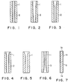
- FIG. 1 A general side view in longitudinal section of a nozzle in which the above described tube is used is shown in FIG. 1.
- This structure comprises the tube 1 and an outer cylinder 2 enveloping the tube 1 for protecting and reinforcing the same.
- This example illustrates the case where an inner cylinder, consisting of silicon carbide tube 1 of circular cross section having a constant diameter in its longitudinal direction, is fixed integrally to the interior wall surface of an outer cylinder 2 made of a metal or an ultrahard metal alloy.
- This fixing between the inner and outer cylinders is carried out by a method such as brazing or bonding.
- shrinkage fitting is also possible.
- an ultrahigh-velocity jet of water containing abrasive particles therein passes through the ejection orifice formed by the tube.
- the inner wall of this ejection orifice is formed from a polycrystalline silicon carbide of excellent resistance against abrasive wear. Therefore the rate of its wear is low, whereby the tube can withstand use over a long service period.
- a nozzle is produced as shown in FIG. 2, wherein the inner diameter of the polycrystalline silicon carbide tube 1 varies linearly at a constant rate in a tapering manner in the longitudinal direction, decreasing toward the discharge end at the bottom as viewed in the figure.
- the tube 1 and the outer cylinder 2 are fixedly joined by the same method as in the first example.
- a nozzle is produced as illustrated in FIG. 3, wherein the inner diameter of the silicon carbide tube 1 varies continuously in the longitudinal direction, whereby the contour of each side of the tube 1 as viewed in the sectional view of FIG. 3 is a continuous fair curve.
- the tube 1 and the outer cylinder 2 are fixedly joined in the same manner as in the preceding examples.
- a nozzle is produced as shown in FIG. 4, wherein the silicon carbide tube 1 is funnel shaped at the entrance end thereof.
- the tube 1 and the outer cylinder 2 are fixedly joined in the same manner as in the preceding examples.
- FIG. 5 illustrates one example of a further mode of practice of this invention in which a polycrystalline silicon carbide tube 1 is produced which is a homogeneous unit structure of a thick wall constituting a nozzle without an outer cylinder 2.
- the tube can be used without the outer cylinder 2 to function as a reinforcing part.
- the outer cylindrical surface can also be processed.
- a nozzle is produced as shown in FIG. 6, wherein the tube 1 is reinforced by an outer cylinder 3 which is a sintered metal structure.
- the polycrystalline silicon carbide tube 1 and the outer cylinder 3 are sintered together to form an integral structure.
- the inner diameter of the tube 1 varies continuously, contracting in the downward direction from the entrance to a constricted throat portion and then expanding toward the discharge orifice.
- the contour of this tube 1 as viewed in the longitudinal section of FIG. 6 comprises two continuous fair curves in symmetrical opposition.
- the present invention has been described with respect to wear resistant structures made of silicon carbide prepared by vapor-phase synthesis and adapted for use as nozzles for ejecting ultrahigh-velocity jets containing abrasives and passing therethrough.
- the polycrystalline silicon carbide tube produced according to this invention is used as an abrasive-water-jet nozzle or as a structure constituting an inner wall surface in the fabrication of a nozzle for ejecting a fluid under high pressure. For this reason, the diameter of the high-velocity jet ejected from the nozzle remains stable over a long period. Accordingly the frequency of replacement of the nozzle is decreased, and the work efficiency and material working precision are greatly improved.
Landscapes
- Engineering & Computer Science (AREA)
- Chemical & Material Sciences (AREA)
- Ceramic Engineering (AREA)
- Organic Chemistry (AREA)
- Manufacturing & Machinery (AREA)
- Materials Engineering (AREA)
- Structural Engineering (AREA)
- Mechanical Engineering (AREA)
- Inorganic Chemistry (AREA)
- Carbon And Carbon Compounds (AREA)
- Nozzles (AREA)
- Ceramic Products (AREA)
- Perforating, Stamping-Out Or Severing By Means Other Than Cutting (AREA)
- Producing Shaped Articles From Materials (AREA)
- Crystals, And After-Treatments Of Crystals (AREA)
- Manufacturing Of Tubular Articles Or Embedded Moulded Articles (AREA)
- Pharmaceuticals Containing Other Organic And Inorganic Compounds (AREA)
- Polishing Bodies And Polishing Tools (AREA)
Abstract
Description
- The present invention relates to a process for producing a silicon carbide abrasive-water-jet nozzle for working articles with an abrasive-water-jet propelled therethrough, the water jet of the abrasive type containing particles of abrasives such as garnet and alumina admixed therein.
- As is known, a water-jet working or machining apparatus operates to eject water under high pressure through a nozzle of small throat diameter thereby to render the water into a jet of supersonic velocity and to direct this jet against a workpiece material to work the same. By this technique, almost any kind of material such as plastics, papers, and metal alloys can be worked. During this working or machining, there is almost no scattering of dust or generation of heat, and three-dimensional machining is also possible. In order to further increase the precision and speed of the working process, abrasive type water jets containing particles of abrasives such as alumina and garnet are also being developed.
- The inner surface of the nozzle constituting the flow path and orifice for discharging the water jet is subject to severe abrasion and wear. Accordingly, materials such as cemented carbide alloys, refractory hard metals, and alumina ceramics are ordinarily being used for these nozzles. There are also nozzles made of sintered skeletons of cubic boron nitride as disclosed, for example, in Japanese Utility Model Appln. Laid-Open No. 63-50700 published April 6, 1988. These materials, however, are of high price. Moreover, in the present state of the art, these materials do not exhibit durability to a degree commensurately expectable from the intrinsic hardnesses of these materials.
- Silicon carbide is a material next in hardness to diamond and cubic boron nitride. Moreover its deposition by the vapor-phase synthesis method is relatively easy. Therefore, silicon carbide is a promising material for nozzles of the instant character.
- Formed articles of silicon carbide of the prior art have been produced by mixing various sintering aids such as carbon, boron, and aluminum into a fine powder of silicon carbide synthesized by the Acheson process, for example, forming the mixture into the desired shape, and then sintering the same. It has been found that, when this material is used for a water-jet nozzle, it does not exhibit a durability expectable from the intrinsic hardness of silicon carbide. The cause of this disappointing result is considered to be that, because the sintering aids wear away first, or the bonding with the sintering aids is insufficient, the particles of silicon carbide become free and drop off, whereby the intrinsic hardness of silicon carbide cannot be amply utilized.
- From Ceramic Engineering and Science Proceedings 8 (7/8), pages 958-967 (1987) it is known to produce SiC nozzles by CVD-inside diameter deposition on a sacrificial graphite substrate. It is further known therefrom to produce a nut-and-bolt assembly by a combination of inside and outside deposits on graphite.
- Chemical Abstracts, 71 (22): 104 733 m discloses chemical vapor deposition of SiC onto machined substrates of graphite and metals in order to form parts with high temperature and high hardness characteristics, e.g. rocket nozzle liners.
- A problem encountered hitherto has been the strict requirement for precision of shape because of the minute inner diameter of a water-jet nozzle of the order of 1 mm. For this reason, the forming of a water-jet nozzle from sintered silicon carbide has been thought to be difficult.
- We have made a study of chemical vapor-phase synthesis processes with the view of providing a process for obtaining immediately in a desired shape a silicon carbide of high purity containing no sintering aids. As a result, we have found that a nozzle produced by such a process has a performance superior to that of a conventional sintered silicon carbide product. We have thus arrived at the present invention.
- According to this invention there is provided a process for producing a silicon carbide abrasive-water-jet nozzle for working articles with an abrasive-water-jet propelled therethrough, by vapor phase deposition of silicon carbide on a graphite structure and removing the graphite structure thereafter, characterized by the steps of:
preparing a rod-shaped graphite structure having an outer surface shape corresponding to the shape of an internal hole of the water-jet nozzle;
depositing silcon carbide on the outer surface of the graphite structure by a vapor-phase synthesis method, such that the silicon carbide will form a tubular structure on the outer surface of the graphite structure, said tubular structure having a density of from 3.18 to 3.21 g/cm³ and a maximum impurity content of 20 ppm; and
thereafter separating the tubular structure from the graphite structure by heating the graphite structure in air, thus obtaining a water-jet nozzle having the internal hole of high precision and high durability to abrasion and wear. - The nature, utility, and further features of this invention will be more clearly apparent from the following detailed description including preferred embodiments of the invention when read in conjunction with the accompanying drawings.
-
- FIG. 1 is a side view, in longitudinal section, of a nozzle produced according to the process of this invention;
- FIGS. 2 through 6 are similar views respectively illustrating other types of nozzles produced according to the process of the invention; and
- FIG. 7 is a view explanatory of the process according to this invention.
- The higher the density of the nozzle material, the more desirable it is. That of the nozzle produced according to this invention is 3.18 g/cm³ or higher. The upper limit of this density can be made almost equal to the theoretical density of 3.21 g/cm³. Moreover, the resulting material is almost fully impervious to gases.
- The silicon carbide nozzles produced according to this invention can be of various forms as illustrated by only a few examples in the accompanying drawings. Suitable dimensions of the nozzles are within ranges of outer diameter of 1 to 10 mm and of inner diameter of 0.1 to 4.8 mm.
- These nozzles are produced in the following manner.
- It is not possible to fabricate a nozzle of this invention by sintering a powder compact of SiC or by sintering a moulded powder of silicon carbide. The nozzle is made by chemical vapor-phase synthesis.
- For preparing silicon carbide by a chemical vapor-phase synthesis process, a substance to become the base material is necessary. In the practice of this invention, for fabricating silicon carbide in the form of a nozzle, a base material of the shape of a cylindrical rod of a specific diameter is used. The substance is graphite. Particularly in the case where impurities are to be avoided, refined graphite is used. Each rod is fabricated to a length conforming to the length of the water-jet nozzle. Then, silicon carbide is deposited onto the base material by evaporating SiC precursors and feeding them to the deposition site where they react at high temperature, thereby forming SiC deposits on the base material. In this connection, the thermal expansion coefficient of the silicon carbide deposited is approximately 4.5 × 10⁻⁶ l/°C. For this reason, a graphite of a thermal expansion coefficient of from 4.5 × 10⁻⁶ to 5.0 × 10⁻⁶ l/°C was used for the base material.
- As the chemical vapor-phase method, any suitable known method may be used. One example of such a method is that in which a silane hydrocarbon such as methyltrichlorosilane and hydrogen gas are used. Another example is a method in which a silane gas and a hydrocarbon gas diluted with hydrogen gas are used. Still another example is a method in which SiO gas and CO gas which are generated from SiO₂ and carbon (graphite) are used.
- By such a chemical vapor-phase method, a graphite base material of rod shape covered with silicon carbide to a specific coating thickness is obtained. By cutting this base material to a specific length and removing the graphite base material by an oxidation method in air, a tube of silicon carbide of a specific desired shape can be fabricated. The tube thus fabricated can be used by any of various methods. One is the method of brazing or bonding the tube to the inner surface of an ultrahard nozzle. Another is the method of depositing silicon carbide to a great thickness and using the tube directly as it is as an abrasive-water-jet nozzle.
- By a chemical vapor-phase synthesis process as described above, a polycrystalline silicon carbide of high purity not containing any sintering aid is obtained. Moreover, since the polycrystalline particles are finely bonded, the product has a high density and is impervious to fluids. Therefore the resistance of the water-jet nozzle to abrasive wear is remarkably improved.
- By machining a workpiece of isotropic graphite, a round rod G (FIG. 7) of graphite of a diameter of 1.8 mm and a length of 45 mm was obtained. This round rod G as a base material was heated at 1,700°C in a gaseous atmosphere of SiO and CO gases thereby to deposit a polycrystalline film 1a of silicon carbide of a film thickness of 2 mm on the surface of the round rod G.
- The silicon carbide film 1a thus deposited on the end faces of the round rod G was scraped off as indicated at 1b in FIG. 7. The rod G together with the film 1a was then heated at 800°C in air, whereupon the rod G is burned and removed and a silicon carbide cube of an inner diameter of 1.8 mm, a wall thickness of 2 mm, and a length of 40 mm was obtained.
- The thus obtained tube had a density of 3.21 g/cm³ and an impurity content of 5 ppm and was almost completely impervious to gases.
- By this method, various tubes as described below were fabricated and used as nozzles.
- A general side view in longitudinal section of a nozzle in which the above described tube is used is shown in FIG. 1. This structure comprises the
tube 1 and anouter cylinder 2 enveloping thetube 1 for protecting and reinforcing the same. This example illustrates the case where an inner cylinder, consisting ofsilicon carbide tube 1 of circular cross section having a constant diameter in its longitudinal direction, is fixed integrally to the interior wall surface of anouter cylinder 2 made of a metal or an ultrahard metal alloy. This fixing between the inner and outer cylinders is carried out by a method such as brazing or bonding. However, in the case where the outer diameter of the tube is large, shrinkage fitting is also possible. - In the operation of the nozzle of the above described construction, an ultrahigh-velocity jet of water containing abrasive particles therein passes through the ejection orifice formed by the tube. The inner wall of this ejection orifice is formed from a polycrystalline silicon carbide of excellent resistance against abrasive wear. Therefore the rate of its wear is low, whereby the tube can withstand use over a long service period.
- In another preferred mode of practice of this invention a nozzle is produced as shown in FIG. 2, wherein the inner diameter of the polycrystalline
silicon carbide tube 1 varies linearly at a constant rate in a tapering manner in the longitudinal direction, decreasing toward the discharge end at the bottom as viewed in the figure. Thetube 1 and theouter cylinder 2 are fixedly joined by the same method as in the first example. - In still another mode of practice of this invention a nozzle is produced as illustrated in FIG. 3, wherein the inner diameter of the
silicon carbide tube 1 varies continuously in the longitudinal direction, whereby the contour of each side of thetube 1 as viewed in the sectional view of FIG. 3 is a continuous fair curve. Thetube 1 and theouter cylinder 2 are fixedly joined in the same manner as in the preceding examples. - In still another mode of practice of this invention a nozzle is produced as shown in FIG. 4, wherein the
silicon carbide tube 1 is funnel shaped at the entrance end thereof. Thetube 1 and theouter cylinder 2 are fixedly joined in the same manner as in the preceding examples. - FIG. 5 illustrates one example of a further mode of practice of this invention in which a polycrystalline
silicon carbide tube 1 is produced which is a homogeneous unit structure of a thick wall constituting a nozzle without anouter cylinder 2. In this case where the wall of thetube 1 is thick, the tube can be used without theouter cylinder 2 to function as a reinforcing part. Furthermore, it is also possible to machine (grind) the tapered funnel-shaped entrance after thetube 1 has been formed. Depending on the necessity, the outer cylindrical surface can also be processed. - In a further mode of practice of this invention a nozzle is produced as shown in FIG. 6, wherein the
tube 1 is reinforced by anouter cylinder 3 which is a sintered metal structure. The polycrystallinesilicon carbide tube 1 and theouter cylinder 3 are sintered together to form an integral structure. In this example, the inner diameter of thetube 1 varies continuously, contracting in the downward direction from the entrance to a constricted throat portion and then expanding toward the discharge orifice. The contour of thistube 1 as viewed in the longitudinal section of FIG. 6 comprises two continuous fair curves in symmetrical opposition. - In the above described examples, the present invention has been described with respect to wear resistant structures made of silicon carbide prepared by vapor-phase synthesis and adapted for use as nozzles for ejecting ultrahigh-velocity jets containing abrasives and passing therethrough.
- With respect to the above described examples of modes of practice and other possible modes, in the nozzles produced according to the process of the invention various modifications and alternative combinations are possible in features, within the scope of the invention as defined by the claims, such as the shapes of the inner wall surfaces of the tubes in longitudinal section and in cross-section, the external shape, and the method of joining of the inner tube and the outer cylinder.
- As described above, the polycrystalline silicon carbide tube produced according to this invention is used as an abrasive-water-jet nozzle or as a structure constituting an inner wall surface in the fabrication of a nozzle for ejecting a fluid under high pressure. For this reason, the diameter of the high-velocity jet ejected from the nozzle remains stable over a long period. Accordingly the frequency of replacement of the nozzle is decreased, and the work efficiency and material working precision are greatly improved.
Claims (9)
- A process for producing a silicon carbide abrasive-water-jet nozzle for working articles with an abrasive-water-jet propelled therethrough, by vapor phase deposition of silicon carbide on a graphite structure and removing the graphite structure thereafter,
characterized by the steps of:
preparing a rod-shaped graphite structure having an outer surface shape corresponding to the shape of an internal hole of the water-jet nozzle;
depositing silicon carbide on the outer surface of the graphite structure by a vapor-phase synthesis method, such that the silicon carbide will form a tubular structure (1) on the outer surface of the graphite structure, said tubular structure (1) having a density of from 3.18 to 3.21 g/cm³ and a maximum impurity content of 20 ppm; and
thereafter separating the tubular structure (1) from the graphite structure by heating the graphite structure in air, thus obtaining a water-jet nozzle having the internal hole of high precision and high durability to abrasion and wear. - The process according to claim 1,
characterized in that
said step of depositing silicon carbide comprises the step of:
heating the rod-shaped graphite structure in a gaseous atmosphere of a compound or compounds containing silicon and carbon to deposit a polycrystalline film of silicon carbide on the graphite structure. - The process according to claim 2,
characterized in that
said compound is a silane hydrocarbon. - The process according to claim 2 or 3,
characterized in that
said compound is a silane gas and a hydrocarbon gas. - The process according to any one of claims 2 to 4,
characterized in that
said compound is a SiO gas and a CO gas. - The process according to any one of claims 2 to 5,
characterized in that
said rod-shaped graphite structure is heated at 1,700°C. - The process according to any one of claims 1 to 6,
characterized in that
it further comprises the step of:
scraping off the silicon carbide (1b) deposited on end faces of the rod-shaped graphite structure (G) before separating the tubular structure (1) from the graphite structure. - The process according to any one of claims 1 to 7,
characterized in that
the graphite structure is heated at 800°C to separate the tubular structure (1) from the graphite structure (G). - The process according to any one of claims 1 to 8,
characterized in that
it further comprises the step of:
securing an outer cylinder (2) to an outer surface of said tubular structure (1).
Applications Claiming Priority (2)
| Application Number | Priority Date | Filing Date | Title |
|---|---|---|---|
| JP1283545A JP2628919B2 (en) | 1989-10-31 | 1989-10-31 | Abrasive type water jet nozzle and method of manufacturing the same |
| JP283545/89 | 1989-10-31 |
Publications (2)
| Publication Number | Publication Date |
|---|---|
| EP0426121A1 EP0426121A1 (en) | 1991-05-08 |
| EP0426121B1 true EP0426121B1 (en) | 1995-10-11 |
Family
ID=17666913
Family Applications (1)
| Application Number | Title | Priority Date | Filing Date |
|---|---|---|---|
| EP90120818A Expired - Lifetime EP0426121B1 (en) | 1989-10-31 | 1990-10-30 | Process for the production of silicon carbide abrasive-water-jet nozzle |
Country Status (9)
| Country | Link |
|---|---|
| US (1) | US5407503A (en) |
| EP (1) | EP0426121B1 (en) |
| JP (1) | JP2628919B2 (en) |
| KR (1) | KR940003474B1 (en) |
| CN (1) | CN1023446C (en) |
| AT (1) | ATE128957T1 (en) |
| AU (1) | AU638764B2 (en) |
| CA (1) | CA2028894C (en) |
| DE (1) | DE69022952T2 (en) |
Families Citing this family (13)
| Publication number | Priority date | Publication date | Assignee | Title |
|---|---|---|---|---|
| US5431346A (en) * | 1993-07-20 | 1995-07-11 | Sinaisky; Nickoli | Nozzle including a venturi tube creating external cavitation collapse for atomization |
| JP3166025B2 (en) * | 1994-10-17 | 2001-05-14 | 信越化学工業株式会社 | Nozzle for fluidized bed type mixing / dispersing device |
| DE19640920C1 (en) * | 1996-10-04 | 1998-01-22 | Saechsische Werkzeug Und Sonde | Focussing nozzle for cutting by abrasive water-jet |
| US5921846A (en) * | 1997-03-21 | 1999-07-13 | The Johns Hopkins University | Lubricated high speed fluid cutting jet |
| US6152506A (en) * | 1997-07-22 | 2000-11-28 | Matsushita Electric Industrial Co., Ltd. | Nozzle block of electronic part suction holding nozzle |
| US5985186A (en) * | 1998-02-19 | 1999-11-16 | Gas Research Institute | Method of preparing tubular ceramic articles |
| US6106751A (en) * | 1998-03-18 | 2000-08-22 | The Regents Of The University Of California | Method for fabricating needles via conformal deposition in two-piece molds |
| US6425805B1 (en) | 1999-05-21 | 2002-07-30 | Kennametal Pc Inc. | Superhard material article of manufacture |
| EP1574290A1 (en) * | 2004-03-11 | 2005-09-14 | Procer SAS | Jet cutting focussing tube device and process of making same |
| US20080265005A1 (en) * | 2007-04-30 | 2008-10-30 | United Technologies Corporation | Brazing process incorporating graphitic preforms |
| US20100088894A1 (en) * | 2008-10-10 | 2010-04-15 | Stark Roger M | Method for preparing abrasive waterjet mixing tubes |
| CN101579843B (en) * | 2009-01-20 | 2012-05-30 | 江苏工业学院 | Method for manufacturing man-made polycrystalline diamond nozzle |
| KR101281551B1 (en) * | 2011-12-15 | 2013-07-03 | 주식회사 티씨케이 | Manufacturing method for focus ring of dry etching device |
Family Cites Families (16)
| Publication number | Priority date | Publication date | Assignee | Title |
|---|---|---|---|---|
| US3011912A (en) * | 1959-12-22 | 1961-12-05 | Union Carbide Corp | Process for depositing beta silicon carbide |
| US3961003A (en) * | 1972-05-17 | 1976-06-01 | Dow Corning Corporation | Method and apparatus for making elongated Si and SiC structures |
| JPS5180317A (en) * | 1975-01-07 | 1976-07-13 | Tokai Carbon Kk | |
| DE2821595A1 (en) * | 1978-05-17 | 1983-04-14 | Max-Planck-Gesellschaft zur Förderung der Wissenschaften e.V., 3400 Göttingen | HIGH STRENGTH CERAMIC COMPOSITE TUBE, ITS PRODUCTION AND USE |
| DE3133209C2 (en) * | 1981-08-21 | 1985-04-25 | MTU Motoren- und Turbinen-Union München GmbH, 8000 München | Hollow composite body, in particular body of revolution and method for its production |
| US4459338A (en) * | 1982-03-19 | 1984-07-10 | The United States Of America As Represented By The United States Department Of Energy | Method of deposition of silicon carbide layers on substrates and product |
| US4500483A (en) * | 1982-03-19 | 1985-02-19 | United Technologies Corporation | Manufacture of hollow CVD silicon nitride articles |
| US4555872A (en) * | 1982-06-11 | 1985-12-03 | Fluidyne Corporation | High velocity particulate containing fluid jet process |
| JPS6056089B2 (en) * | 1982-06-28 | 1985-12-09 | 吉田工業株式会社 | A method for three-dimensionally molding an embossed pattern of a shiny surface on the surface of a synthetic resin molded product, and a molded product molded by the method |
| JPH0631185B2 (en) * | 1986-02-06 | 1994-04-27 | 東芝セラミツクス株式会社 | Method for manufacturing silicon carbide heating element |
| JPS62179049U (en) * | 1986-05-01 | 1987-11-13 | ||
| JPS6328145U (en) * | 1986-08-06 | 1988-02-24 | ||
| JPS6350700A (en) * | 1986-08-18 | 1988-03-03 | Torishima Seisakusho:Kk | Flat plate linear inducer for pump and device for manufacturing thereof |
| US4861533A (en) * | 1986-11-20 | 1989-08-29 | Air Products And Chemicals, Inc. | Method of preparing silicon carbide capillaries |
| US4999228A (en) * | 1988-05-06 | 1991-03-12 | Shin-Etsu Chemical Co., Ltd. | Silicon carbide diffusion tube for semi-conductor |
| US5011566A (en) * | 1989-03-15 | 1991-04-30 | The United States Of America As Represented By The Secretary Of The Air Force | Method of manufacturing microscopic tube material |
-
1989
- 1989-10-31 JP JP1283545A patent/JP2628919B2/en not_active Expired - Fee Related
-
1990
- 1990-10-29 KR KR1019900017352A patent/KR940003474B1/en not_active IP Right Cessation
- 1990-10-30 AU AU65621/90A patent/AU638764B2/en not_active Ceased
- 1990-10-30 DE DE69022952T patent/DE69022952T2/en not_active Expired - Fee Related
- 1990-10-30 EP EP90120818A patent/EP0426121B1/en not_active Expired - Lifetime
- 1990-10-30 AT AT90120818T patent/ATE128957T1/en not_active IP Right Cessation
- 1990-10-30 CA CA002028894A patent/CA2028894C/en not_active Expired - Fee Related
- 1990-10-31 CN CN90109657A patent/CN1023446C/en not_active Expired - Fee Related
-
1993
- 1993-10-21 US US08/139,045 patent/US5407503A/en not_active Expired - Fee Related
Also Published As
| Publication number | Publication date |
|---|---|
| AU6562190A (en) | 1991-05-09 |
| US5407503A (en) | 1995-04-18 |
| DE69022952T2 (en) | 1996-05-30 |
| CA2028894A1 (en) | 1991-05-01 |
| JP2628919B2 (en) | 1997-07-09 |
| EP0426121A1 (en) | 1991-05-08 |
| CN1052444A (en) | 1991-06-26 |
| KR910008324A (en) | 1991-05-31 |
| KR940003474B1 (en) | 1994-04-22 |
| AU638764B2 (en) | 1993-07-08 |
| JPH03146413A (en) | 1991-06-21 |
| DE69022952D1 (en) | 1995-11-16 |
| ATE128957T1 (en) | 1995-10-15 |
| CA2028894C (en) | 1997-08-26 |
| CN1023446C (en) | 1994-01-12 |
Similar Documents
| Publication | Publication Date | Title |
|---|---|---|
| EP0426121B1 (en) | Process for the production of silicon carbide abrasive-water-jet nozzle | |
| US5363556A (en) | Water jet mixing tubes used in water jet cutting devices and method of preparation thereof | |
| US20020094379A1 (en) | Cast diamond tools and formation thereof by chemical vapor deposition | |
| EP0087798B1 (en) | A method and apparatus for making a fine powder compound of a metal and another element | |
| US4960643A (en) | Composite synthetic materials | |
| Dickerson et al. | Near net-shape, ultra-high melting, recession-resistant ZrC/W-based rocket nozzle liners via the displacive compensation of porosity (DCP) method | |
| KR100212120B1 (en) | Cvd diamond workpieces and their fabrication | |
| US6969313B2 (en) | Cast diamond tools and formation thereof by chemical vapor deposition | |
| EP0435854A2 (en) | Method of sintering metal-dispersed reinforced ceramics | |
| EP1423480B1 (en) | Cubic boron nitride composition, coating and articles made therefrom, methods of making and using said composition, coating and articles | |
| EP0712941B1 (en) | Diamond sinter, high-pressure phase boron nitride sinter, and processes for producing those sinters | |
| KR20120039731A (en) | Supported pcd and manufacturing method using binderless wc-substrate | |
| JP2599044B2 (en) | High pressure injection nozzle | |
| JPH0753269A (en) | Coated high pressure type boron nitride sintered body and its production | |
| Casto et al. | Wear performance of ceramic cutting tool materials when cutting steel | |
| JPH0634936Y2 (en) | Water jet nozzle | |
| JP3053652B2 (en) | Diamond-containing sintered material | |
| JPH04331798A (en) | Method of forming diamond film | |
| RU2018411C1 (en) | Article, mainly cutting tool, containing sintered base of tungsten carbide base and diamond coating | |
| JPH0551267A (en) | Sintering material for tool | |
| JPH0671503A (en) | Diamond cutting tool and its manufacture | |
| JPH08224462A (en) | Reactor | |
| JPH0753270A (en) | Coated high pressure type boron nitride sintered body and its production | |
| JPH04119983A (en) | Diamond-coated ceramic base material | |
| JPH09268070A (en) | Production of ceramic sintered compact |
Legal Events
| Date | Code | Title | Description |
|---|---|---|---|
| PUAI | Public reference made under article 153(3) epc to a published international application that has entered the european phase |
Free format text: ORIGINAL CODE: 0009012 |
|
| 17P | Request for examination filed |
Effective date: 19901031 |
|
| AK | Designated contracting states |
Kind code of ref document: A1 Designated state(s): AT DE FR GB IT NL |
|
| 17Q | First examination report despatched |
Effective date: 19930823 |
|
| GRAA | (expected) grant |
Free format text: ORIGINAL CODE: 0009210 |
|
| K1C1 | Correction of patent application (title page) published |
Effective date: 19910508 |
|
| R17P | Request for examination filed (corrected) |
Effective date: 19901030 |
|
| AK | Designated contracting states |
Kind code of ref document: B1 Designated state(s): AT DE FR GB IT NL |
|
| REF | Corresponds to: |
Ref document number: 128957 Country of ref document: AT Date of ref document: 19951015 Kind code of ref document: T |
|
| REF | Corresponds to: |
Ref document number: 69022952 Country of ref document: DE Date of ref document: 19951116 |
|
| ET | Fr: translation filed | ||
| ITF | It: translation for a ep patent filed |
Owner name: MODIANO & ASSOCIATI S.R.L. |
|
| PLBE | No opposition filed within time limit |
Free format text: ORIGINAL CODE: 0009261 |
|
| STAA | Information on the status of an ep patent application or granted ep patent |
Free format text: STATUS: NO OPPOSITION FILED WITHIN TIME LIMIT |
|
| 26N | No opposition filed | ||
| PGFP | Annual fee paid to national office [announced via postgrant information from national office to epo] |
Ref country code: AT Payment date: 20001011 Year of fee payment: 11 |
|
| PGFP | Annual fee paid to national office [announced via postgrant information from national office to epo] |
Ref country code: NL Payment date: 20001026 Year of fee payment: 11 |
|
| PG25 | Lapsed in a contracting state [announced via postgrant information from national office to epo] |
Ref country code: AT Free format text: LAPSE BECAUSE OF NON-PAYMENT OF DUE FEES Effective date: 20011030 |
|
| REG | Reference to a national code |
Ref country code: GB Ref legal event code: IF02 |
|
| PG25 | Lapsed in a contracting state [announced via postgrant information from national office to epo] |
Ref country code: NL Free format text: LAPSE BECAUSE OF NON-PAYMENT OF DUE FEES Effective date: 20020501 |
|
| NLV4 | Nl: lapsed or anulled due to non-payment of the annual fee |
Effective date: 20020501 |
|
| PGFP | Annual fee paid to national office [announced via postgrant information from national office to epo] |
Ref country code: FR Payment date: 20031003 Year of fee payment: 14 |
|
| PGFP | Annual fee paid to national office [announced via postgrant information from national office to epo] |
Ref country code: GB Payment date: 20031029 Year of fee payment: 14 |
|
| PGFP | Annual fee paid to national office [announced via postgrant information from national office to epo] |
Ref country code: DE Payment date: 20031103 Year of fee payment: 14 |
|
| PG25 | Lapsed in a contracting state [announced via postgrant information from national office to epo] |
Ref country code: GB Free format text: LAPSE BECAUSE OF NON-PAYMENT OF DUE FEES Effective date: 20041030 |
|
| PG25 | Lapsed in a contracting state [announced via postgrant information from national office to epo] |
Ref country code: DE Free format text: LAPSE BECAUSE OF NON-PAYMENT OF DUE FEES Effective date: 20050503 |
|
| GBPC | Gb: european patent ceased through non-payment of renewal fee |
Effective date: 20041030 |
|
| PG25 | Lapsed in a contracting state [announced via postgrant information from national office to epo] |
Ref country code: FR Free format text: LAPSE BECAUSE OF NON-PAYMENT OF DUE FEES Effective date: 20050630 |
|
| REG | Reference to a national code |
Ref country code: FR Ref legal event code: ST |
|
| PG25 | Lapsed in a contracting state [announced via postgrant information from national office to epo] |
Ref country code: IT Free format text: LAPSE BECAUSE OF NON-PAYMENT OF DUE FEES;WARNING: LAPSES OF ITALIAN PATENTS WITH EFFECTIVE DATE BEFORE 2007 MAY HAVE OCCURRED AT ANY TIME BEFORE 2007. THE CORRECT EFFECTIVE DATE MAY BE DIFFERENT FROM THE ONE RECORDED. Effective date: 20051030 |