EP0426041B1 - Système d'étanchéité à gorge spiralée pour gaz sous haute pression - Google Patents
Système d'étanchéité à gorge spiralée pour gaz sous haute pression Download PDFInfo
- Publication number
- EP0426041B1 EP0426041B1 EP90120611A EP90120611A EP0426041B1 EP 0426041 B1 EP0426041 B1 EP 0426041B1 EP 90120611 A EP90120611 A EP 90120611A EP 90120611 A EP90120611 A EP 90120611A EP 0426041 B1 EP0426041 B1 EP 0426041B1
- Authority
- EP
- European Patent Office
- Prior art keywords
- seal
- housing
- pressure
- module
- seal module
- Prior art date
- Legal status (The legal status is an assumption and is not a legal conclusion. Google has not performed a legal analysis and makes no representation as to the accuracy of the status listed.)
- Expired - Lifetime
Links
- 238000007789 sealing Methods 0.000 title claims abstract description 27
- 230000013011 mating Effects 0.000 claims abstract description 20
- 230000009467 reduction Effects 0.000 claims abstract description 4
- 239000012530 fluid Substances 0.000 claims description 20
- 238000013022 venting Methods 0.000 claims description 7
- 238000005086 pumping Methods 0.000 claims description 4
- 238000000034 method Methods 0.000 claims 8
- 239000007789 gas Substances 0.000 abstract description 31
- UFHFLCQGNIYNRP-UHFFFAOYSA-N Hydrogen Chemical compound [H][H] UFHFLCQGNIYNRP-UHFFFAOYSA-N 0.000 abstract description 3
- 239000001257 hydrogen Substances 0.000 abstract description 2
- 229910052739 hydrogen Inorganic materials 0.000 abstract description 2
- 238000011144 upstream manufacturing Methods 0.000 description 15
- 239000007788 liquid Substances 0.000 description 6
- 230000008859 change Effects 0.000 description 4
- 125000006850 spacer group Chemical group 0.000 description 4
- 230000000712 assembly Effects 0.000 description 2
- 238000000429 assembly Methods 0.000 description 2
- 230000008901 benefit Effects 0.000 description 2
- 230000015556 catabolic process Effects 0.000 description 2
- 238000005530 etching Methods 0.000 description 2
- 210000004907 gland Anatomy 0.000 description 2
- 230000002706 hydrostatic effect Effects 0.000 description 2
- 230000004308 accommodation Effects 0.000 description 1
- 238000007792 addition Methods 0.000 description 1
- 230000004075 alteration Effects 0.000 description 1
- 238000010276 construction Methods 0.000 description 1
- 230000003247 decreasing effect Effects 0.000 description 1
- 238000010438 heat treatment Methods 0.000 description 1
- 229930195733 hydrocarbon Natural products 0.000 description 1
- 150000002430 hydrocarbons Chemical class 0.000 description 1
- 150000002431 hydrogen Chemical class 0.000 description 1
- 238000005461 lubrication Methods 0.000 description 1
- 230000003068 static effect Effects 0.000 description 1
- 239000013589 supplement Substances 0.000 description 1
- XLYOFNOQVPJJNP-UHFFFAOYSA-N water Substances O XLYOFNOQVPJJNP-UHFFFAOYSA-N 0.000 description 1
Images
Classifications
-
- F—MECHANICAL ENGINEERING; LIGHTING; HEATING; WEAPONS; BLASTING
- F16—ENGINEERING ELEMENTS AND UNITS; GENERAL MEASURES FOR PRODUCING AND MAINTAINING EFFECTIVE FUNCTIONING OF MACHINES OR INSTALLATIONS; THERMAL INSULATION IN GENERAL
- F16J—PISTONS; CYLINDERS; SEALINGS
- F16J15/00—Sealings
- F16J15/16—Sealings between relatively-moving surfaces
- F16J15/34—Sealings between relatively-moving surfaces with slip-ring pressed against a more or less radial face on one member
- F16J15/3404—Sealings between relatively-moving surfaces with slip-ring pressed against a more or less radial face on one member and characterised by parts or details relating to lubrication, cooling or venting of the seal
- F16J15/3408—Sealings between relatively-moving surfaces with slip-ring pressed against a more or less radial face on one member and characterised by parts or details relating to lubrication, cooling or venting of the seal at least one ring having an uneven slipping surface
- F16J15/3412—Sealings between relatively-moving surfaces with slip-ring pressed against a more or less radial face on one member and characterised by parts or details relating to lubrication, cooling or venting of the seal at least one ring having an uneven slipping surface with cavities
-
- F—MECHANICAL ENGINEERING; LIGHTING; HEATING; WEAPONS; BLASTING
- F16—ENGINEERING ELEMENTS AND UNITS; GENERAL MEASURES FOR PRODUCING AND MAINTAINING EFFECTIVE FUNCTIONING OF MACHINES OR INSTALLATIONS; THERMAL INSULATION IN GENERAL
- F16J—PISTONS; CYLINDERS; SEALINGS
- F16J15/00—Sealings
- F16J15/002—Sealings comprising at least two sealings in succession
- F16J15/006—Sealings comprising at least two sealings in succession with division of the pressure
-
- F—MECHANICAL ENGINEERING; LIGHTING; HEATING; WEAPONS; BLASTING
- F16—ENGINEERING ELEMENTS AND UNITS; GENERAL MEASURES FOR PRODUCING AND MAINTAINING EFFECTIVE FUNCTIONING OF MACHINES OR INSTALLATIONS; THERMAL INSULATION IN GENERAL
- F16J—PISTONS; CYLINDERS; SEALINGS
- F16J15/00—Sealings
- F16J15/16—Sealings between relatively-moving surfaces
- F16J15/34—Sealings between relatively-moving surfaces with slip-ring pressed against a more or less radial face on one member
- F16J15/3464—Mounting of the seal
- F16J15/348—Pre-assembled seals, e.g. cartridge seals
- F16J15/3484—Tandem seals
-
- Y—GENERAL TAGGING OF NEW TECHNOLOGICAL DEVELOPMENTS; GENERAL TAGGING OF CROSS-SECTIONAL TECHNOLOGIES SPANNING OVER SEVERAL SECTIONS OF THE IPC; TECHNICAL SUBJECTS COVERED BY FORMER USPC CROSS-REFERENCE ART COLLECTIONS [XRACs] AND DIGESTS
- Y10—TECHNICAL SUBJECTS COVERED BY FORMER USPC
- Y10S—TECHNICAL SUBJECTS COVERED BY FORMER USPC CROSS-REFERENCE ART COLLECTIONS [XRACs] AND DIGESTS
- Y10S277/00—Seal for a joint or juncture
- Y10S277/921—Closure or weather strip seal
-
- Y—GENERAL TAGGING OF NEW TECHNOLOGICAL DEVELOPMENTS; GENERAL TAGGING OF CROSS-SECTIONAL TECHNOLOGIES SPANNING OVER SEVERAL SECTIONS OF THE IPC; TECHNICAL SUBJECTS COVERED BY FORMER USPC CROSS-REFERENCE ART COLLECTIONS [XRACs] AND DIGESTS
- Y10—TECHNICAL SUBJECTS COVERED BY FORMER USPC
- Y10S—TECHNICAL SUBJECTS COVERED BY FORMER USPC CROSS-REFERENCE ART COLLECTIONS [XRACs] AND DIGESTS
- Y10S277/00—Seal for a joint or juncture
- Y10S277/928—Seal including pressure relief or vent feature
Definitions
- This invention relates to seals for restricting leakage of a fluid about a shaft extending through a housing, such as a turbine or compressor, and in particular a gas under high pressure.
- mechanical seals for sealing gases such as hydrogen
- high pressures for instance, exceeding 84,4 bar (1200 pounds per square inch) gauge
- This system was of the "wet", contacting type which had to be cooled and lubricated by a buffer liquid pumped between the two spaced mechanical seals.
- the system for circulating the buffer liquid included pumps, coolers and reservoirs which added complexity and expense.
- the mechanical seals even with their complicated support system, often had a short duration. Complete shutdown of the system is required to replace the seals.
- Another type of seal utilizes the teaching of U.S. Patent No. 4,212,475 to create a seal in equipment handling liquids under high pressures, such as liquefied light hydrocarbons. This type of seal creates shear heating of the sealed fluid between the seal faces of a sealing module of the type having spiral grooves described in U.S. Patent No. 4,212,475.
- WO 88/09891 discloses a seal system for sealing a housing and rotatable shaft against leakage of high vapour-pressure liquids.
- the seal system contains axially spaced spiral-grooved seal modules mounted between the shaft and the housing.
- the upstream seal module functions to change the phase of the liquid, while a downstream module operates as a dry running gas seal.
- One object of the present invention is to provide a dry gas end face seal arrangement which is particularly appropriate for use in equipment handling light gases under very high pressure, for example pressures which may exceed 126,6 bar (1800 p.s.i.) gauge, and to accomplish this by a breakdown or split of pressure across two or more such seals without need for external pressure control devices.
- the solution proposed by the inventors herein is a series of modules each having a pair of sealing faces, of which one seal face is of the spiral groove type, across which there is a pressure drop of predictable (calculated) proportion achieved by altered face geometry (e.g. groove dimension) in each module.
- the pressure drop may be distributed in approximately equal proportions across two or more separate modules, thereby relieving seal stress or overloading without need for external controls.
- Another object of the invention is to enable pressure breakdown, or splitting, to be easily and inexpensively accomplished simply by using spiral groove seal rings of substantially the same profile differing only in groove depth or dam width dimensions, a matter of etching rings of similar profile to afford successive stages of pressure step-down.
- the present invention is directed to a mechanical end face seal system which is particularly appropriate for compressors handling a gas under very high pressure. This is accomplished through the use of a seal arrangement preferably having a high pressure upstream module, and both an intermediate and a downstream seal module, each mounted on a shaft and housing associated with the compressor or pump.
- a seal arrangement preferably having a high pressure upstream module, and both an intermediate and a downstream seal module, each mounted on a shaft and housing associated with the compressor or pump.
- the principles of the invention may be incorporated in an end seal arrangement having only two modules.
- Each seal module has a primary ring affixed to the housing and a mating ring affixed to the shaft.
- the rings have opposing, radially extending faces, one of which has a plurality of radially directed, circumferentially spaced spiral pumping grooves extending from one circumference thereof.
- the grooves of the upstream module exposed to the highest pressure have a predetermined groove restriction from the standpoint of groove dimension, which is considered
- decreased restriction is achieved by increasing the groove depth of the downstream module.
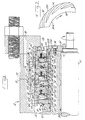
- Fig. 1 illustrates a seal generally indicated at 10 constructed in accordance with the preferred embodiment of the invention.
- the seal is designed to seal gas under very high pressure, for example, hydrogen gas exceeding about 126,6 bar (1800 p.s.i.), in a pump, compressor or turbine housing.
- very high pressure for example, hydrogen gas exceeding about 126,6 bar (1800 p.s.i.
- the invention is at times described with reference to hydrogen gas as a fluid, it is to be understood that other gases or liquids under very high pressures can be handled with the appropriate changes and adjustments to the system to conform the essential parameters to the fluid being sealed.
- a stuffing box or housing is indicated at 12 enclosing the seals and affording a shaft passage 14.
- a shaft 16 extends through the shaft passage from a high pressure chamber 18 in the housing 12 to the atmosphere at 19.
- the seal assembly inside the housing is a tandem arrangement of axially spaced mechanical end face seals of the spiral groove type, each having opposed ring portions respectively secured to the housing 12 and shaft 16.
- the seals are generally of the type shown and described in U.S. Patent No. 4,213,475, referred to above.
- the tandem seal assemblies include a first upstream or inner seal module 20 located in the high pressure chamber 18, at least one second intermediate seal module 22, and, preferably, a third downstream or outer seal module 24 respectively located within annular intermediate and venting chambers 21 and 23 inside the housing.
- Each seal module has a pair of annular rings comprising stationary primary rings 26A, 26B, 26C (ring stators) with radially extending sealing faces 28A, 28B, 28C.
- the primary seal ring elements are opposed to mating rings 30A, 30B, 30C having radially extending sealing faces 32A, 32B, 32C opposite the sealing faces, respectively, 28A, 28B, 28C of the primary rings.
- the primary rings 26A, 26B, 26C are secured to the housing by a retainer assembly, as will be described, while allowing limited axial movement.
- the mating seal rings 30A, 30B, 30C are affixed for rotation with the shaft 16 by a spacer sleeve assembly comprising a ring sleeve 33 and a shaft sleeve 34 keyed thereto, effectively locked to shaft 16 for rotation therewith as will be described.
- the seal shown is exposed to a fluid to be sealed at the radially outer diameter of the seal components.
- the principles of the invention are applicable to seals having the higher pressure at the radially inner diameter of the relatively rotating seal faces.
- the sleeve assembly includes a shaft sleeve 34 which fits upon the shaft 16 and is fixed to the shaft by a clamping end plate 35 secured to shaft sleeve 34 by a bolt 36.
- a drive key arrangement (not shown) may be used to secure shaft sleeve 34 to the shaft 16.
- an O-ring 37 provides a seal between the sleeves 33 and 34. There are additional O-ring seals requiring no elaboration.
- the upstream or high pressure seal module 20, communicating with the high pressure chamber 18, includes an annular support flange 38, Fig. 1, which is an integral portion of sleeve 33.
- Pin 40 connects ring 30A for rotational drive to flange 38.
- the sleeve assembly further includes spacer sleeves 48 keyed for rotation to sleeve 33.
- the sleeves have support flanges 50, holding pins 46 which engage and drive the mating rings 30B, 30C of the intermediate and outboard seal modules 22,24, respectively.
- O-rings 44 are interposed between the opposed faces of the support flanges 50 and the rotating seal rings.
- the spacer sleeves 48 extend to and engage the radial surfaces 32A, 32B adjacent the inside diameter of the mating rings 30A, 30B.
- sleeve 34 is held to shaft 16 for rotation therewith by a drive plate 35.
- the ring sleeve 33 at its inner or upstream end bears against a radially projecting flange 52 on shaft sleeve 34.
- the ring sleeve 33 at its outboard end has a lock collar 53 mounted concentrically thereon.
- the inner end of the lock collar bears against the opposed radially inward circumferential surface of mating ring 30C.
- the outer end of the lock collar 53 has a head or flange 53H secured to the end face of ring sleeve 33 bolt 53B.
- the retainer assembly for the primary rings of the seals comprises inboard, intermediate and outboard retainers 54, 55 and 56 connected one to another by cap screws 57 or otherwise in any suitable fashion.
- the inboard retainer 54 serves to support the inboard primary ring 26A.
- the intermediate retainer 55 supports the intermediate primary ring 26B and the outboard retainer 56 similarly supports the outboard primary ring 26C.
- Each retainer carries multiple springs 58 and a spring disk 60 which together urge the primary seal ring faced into engagement with the grooved faces of the mating rings.
- the disks 60 and springs 58 permit primary rings 26A, 26B and 26C to move axially in either direction.
- O-ring seals 61 provide a secondary seal between the primary rings and retainers 54, 55 and 56.
- a gland plate 62 is connected to housing 12 by screws (not shown).
- the gland plate has a flange 64 engaging the outer end face of the retainer 56.
- the retainer is connected to the flange by cap screws 66.
- vent opening 68 communicates venting chamber 23 with a passage 70 in the housing exposed to atmospheric pressure, allowing gas released from chamber 23 to be transferred to a flare stack or other environment for capturing, using or disposing of the vented gas.
- downstream seal module 24 acts to seal the small amount of gas which may leak from chamber 23; but because of the low pressure of the gas in chamber 23, leakage through seal module 24 will usually be negligible.
- the amount of gas transferring across the dam of this seal module is little (not collectible) and the final pressure at the I.D. may be close to nil. In this sense the third seal may serve as a safety in the event of an obstructed vent for example.
- the advantage of venting chamber 23 via vent passage 68-70 is to bring the noncollectible leakage around the shaft downstream of said module 24 to a minimum.
- a passage 72 to chamber 21 may be provided with a gage attached to be able to read the pressure in chamber 21.
- Mating rings 30A, 30B, 30C each have a series of spiral grooves 92 (shown in phantom in Fig. 1) which will now be discussed in detail with reference to Fig. 2.
- Fig. 2 shows a portion of a mating surface on a mating ring opposed to a primary ring.
- the face 32A of mating ring 30A is shown in Fig. 2.
- the face has a plurality of circumferentially spaced, spiral grooves 92 extending radially from an open end at the outer circumference partially across the radial width of the face 32A.
- the ungrooved surface 94 defines a sealing dam or land which in cooperation with the opposed face of the primary seal ring provides a hydrostatic static seal when the shaft 16 is not rotating. Faces 32B and 32C of the seal modules 22 and 24 are similarly configured to present pumping grooves as 92 and lands 94.
- Intermediate seal 22 itself provides for a further pressure drop across the relatively rotating seal faces from about one-half of full pressure to a pressure slightly above atmospheric pressure.
- chamber 23 has a pressure of about 0,63 to 1,06 bar (9 to 15 p.s.i) over atmospheric pressure, which is the result of the restriction presented by vent passage 68-70 exposed to atmospheric pressure.
- the third seal, and if used, may be present as a mere leakage collector of small capacity. As described above, this gas is vented through vent 68 for disposal in one form or another.
- No seal can be expected to perform constantly in accordance with design limits without some change due to the rigors of performance, coupled with the possibility of mechanical and thermal imbalance not possible to predict or anticipate. Consequently, the third seal may perform redundantly, and if there is a change in pressure profile during service, the result will be a self-adjusting accommodation of pressure drop across the three seal faces as a back-up to either of the upstream seals. Regardless of whether there are two or three seals in tandem, no one seal is subjected to the full pressure load and operates at a level well below its design capability.
- a change in dam width can replace or supplement the groove depth parameter difference.
- two upstream seals e.g. seal modules 20 and 22
- the third seal module becomes the one responsible for the pressure split.
- Various terms and analogies may be used to explain the phenomenon involved at the seal faces when splitting the pressure. The principle employed is that no seal is perfect, and we exploit that circumstance by employing a pair (at least) of tandem end face seals of the spiral groove type so that leakage may be exploited merely by varying groove dimensions without need to alter any other geometry of an inventory of such seals.
- the total gas leakage across each seal, taken as a mass (lbm/min) is the same at each seal. Because the spiral grooves of the downstream seal present a larger volume than those of the upstream seal, the gas has more room for expansion within the larger groove volume and hence is of less density (occupying a larger actual volume) than the gas transferred thereto by the upstream seal grooves. Therefore, while it may be convenient to refer to different volumes (or pumping capacity) being pumped across the respective seal interfaces per unit of time (and at any instant of time), it is to be borne in mind the mass flow rate across each seal is the same at all times.
- the seals may be considered flow restrictors (valves) in which the downstream seal, with deeper spiral grooves (in the preferred form) offers less restriction to gas flow than the one upstream, at the higher pressure.
- the pressure must therefore drop, as when opening the nozzle valve of a garden hose: the rate of water flow is the same as before, when the nozzle was less restrictive, but because the nozzle passage has been widened the stream of fluid now flows out at reduced pressure, covering more area but with less force compared to the more forceful stream reaching a greater distance (more pressure) which prevailed when the nozzle restriction was greater.
Landscapes
- Engineering & Computer Science (AREA)
- General Engineering & Computer Science (AREA)
- Mechanical Engineering (AREA)
- Mechanical Sealing (AREA)
- Gasket Seals (AREA)
- Sealing Devices (AREA)
- Sealing Using Fluids, Sealing Without Contact, And Removal Of Oil (AREA)
- Gas Separation By Absorption (AREA)
- Compressor (AREA)
- Filling Or Discharging Of Gas Storage Vessels (AREA)
- Structures Of Non-Positive Displacement Pumps (AREA)
Claims (6)
- Système d'étanchéité (10) à rainures en spirale, multiple, en tandem, pour empêcher des fuites le long d'un arbre rotatif (16) s'étendant à travers une enveloppe (12) contenant un fluide à mettre en oeuvre sous pression, le système (10) comprenant :
un premier et un deuxième modules d'étanchéité mécaniques rotatifs (20, 22) à faces terminales, espacés axialement et définissant avec l'enveloppe (12) une chambre intermédiaire (21), chaque module d'étanchéité (20, 22) présentant des faces étanchantes opposées s'étendant sensiblement radialement (28A, 32A, 28B, 32B) qui se trouvent sur des bagues primaires (26A, 26B) fixées à l'enveloppe (12) et sur des bagues complémentaires (30A, 30B) tournant avec l'arbre (16), les faces étanchantes (32A, 32B) de chaque bague complémentaire (30A, 30B) présentant un certain nombre de rainures de pompage en spirale (92) s'étendant à travers une partie de la face (32A, 32B) de la bague vers l'intérieur à partir d'une circonférence de celle-ci vers le centre de la face d'étanchéité annulaire (32A, 32B) de la bague, et des moyens (58) pour tendre à pousser les faces étanchantes (28A, 32A, 28B, 32B) des modules d'étanchéité respectifs (20, 22) les unes vers les autres ;
le premier module d'étanchéité (20) étant contigu au fluide à mettre en oeuvre contenu dans l'enveloppe (12) et une circonférence annulaire extérieure des faces étanchantes (28A, 32A) étant exposée au fluide à mettre en oeuvre et une circonférence annulaire intérieure des faces étanchantes (28A, 32A) étant en communication avec la chambre intermédiaire (21), lequel fluide à mettre en oeuvre dans la chambre intermédiaire (21) présente une pression calculée,
caractérisé en ce que le passage, du fluide à mettre en oeuvre, depuis l'enveloppe (12) jusque dans la chambre intermédiaire (21) se produit exclusivement à travers les faces étanchantes (28A, 32A) du premier module d'étanchéité (20) ; en ce que le deuxième module d'étanchéité (22) est contigu à la chambre intermédiaire (21), une circonférence extérieure des faces étanchantes annulaires (28B, 32B) étant exposée au fluide dans la chambre intermédiaire (21) et une circonférence intérieure des faces étanchantes annulaires (28B, 32B) étant exposée à une chambre de détente de pression (23), et en ce que le passage du fluide à partir de la chambre intermédiaire (21) à la chambre de détente (23) se fait exclusivement à travers les faces étanchantes (28B, 32B) du deuxième module d'étanchéité (22). - Système d'étanchéité selon la revendication 1, dans lequel les bagues primaires respectives (26A, 26B) de chaque module d'étanchéité (20, 22) présentent sensiblement la même géométrie de diamètre et d'épaisseur et les bagues complémentaires respectives (30A, 30B) de chaque module d'étanchéité (20, 22) présentent sensiblement la même géométrie de diamètre et d'épaisseur et les dimensions des rainures spirales des modules d'étanchéité respectifs (20, 22) diffèrent de façon à produire une chute de pression prédéterminée du fluide à mettre en oeuvre à travers le deuxième module d'étanchéité (22), laquelle est à peu près égale à une chute de pression préétablie du fluide à travers le premier module d'étanchéité (20).
- Système d'étanchéité selon la revendication 1, dans lequel les dimensions des rainures en spirale des modules d'étanchéité respectifs (20, 22) diffèrent de façon à produire une pression du fluide dans la chambre intermédiaire (21), laquelle est approximativement égale à la moitié de la pression du fluide à mettre en oeuvre dans l'enveloppe (12).
- Système d'étanchéité selon la revendication 1, dans lequel les rainures en spirale (92) de la bague complémentaire (30B) du deuxième module d'étanchéité (22) présentent une capacité volumétrique qui permet de réduire environ de moitié la pression du fluide à travers les faces étanchantes (28A, 32A) du premier module d'étanchéité (20).
- Système d'étanchéité selon la revendication 1, dans lequel la chambre de détente de pression (23) est disposée entre le deuxième module d'étanchéité (22) et un troisième module d'étanchéité (24), et la chambre de détente (23) est en outre mise en communication avec l'atmosphère ambiante (19), extérieure à l'enveloppe (12), par un évent (68).
- Système d'étanchéité selon l'une quelconque des revendications précédentes, dans lequel le fluide à mettre en oeuvre dans l'enveloppe (12) est un gaz sous haute pression.
Applications Claiming Priority (2)
| Application Number | Priority Date | Filing Date | Title |
|---|---|---|---|
| US07/428,952 US5217233A (en) | 1989-10-30 | 1989-10-30 | Spiral groove seal system for sealing a high pressure gas |
| US428952 | 1995-04-26 |
Publications (2)
| Publication Number | Publication Date |
|---|---|
| EP0426041A1 EP0426041A1 (fr) | 1991-05-08 |
| EP0426041B1 true EP0426041B1 (fr) | 1995-05-10 |
Family
ID=23701109
Family Applications (1)
| Application Number | Title | Priority Date | Filing Date |
|---|---|---|---|
| EP90120611A Expired - Lifetime EP0426041B1 (fr) | 1989-10-30 | 1990-10-26 | Système d'étanchéité à gorge spiralée pour gaz sous haute pression |
Country Status (14)
| Country | Link |
|---|---|
| US (1) | US5217233A (fr) |
| EP (1) | EP0426041B1 (fr) |
| JP (1) | JPH03153967A (fr) |
| KR (1) | KR910008320A (fr) |
| CN (1) | CN1023248C (fr) |
| AT (1) | ATE122442T1 (fr) |
| AU (1) | AU629406B2 (fr) |
| BR (1) | BR9005467A (fr) |
| CA (1) | CA2026179A1 (fr) |
| DE (1) | DE69019296T2 (fr) |
| ES (1) | ES2074510T3 (fr) |
| IE (1) | IE67805B1 (fr) |
| MX (1) | MX171433B (fr) |
| ZA (1) | ZA907774B (fr) |
Cited By (1)
| Publication number | Priority date | Publication date | Assignee | Title |
|---|---|---|---|---|
| US11821523B2 (en) | 2019-09-06 | 2023-11-21 | John Crane Inc. | Non-pusher dry gas seal with sealing elastomer and systems utilizing same |
Families Citing this family (51)
| Publication number | Priority date | Publication date | Assignee | Title |
|---|---|---|---|---|
| NZ236907A (en) * | 1991-01-25 | 1994-10-26 | Milcon Developments Nz Ltd | Seal for liquid concentrator; grooved rotating face retains sealing fluid |
| GB9103217D0 (en) * | 1991-02-15 | 1991-04-03 | Crane John Uk Ltd | Mechanical face seals |
| DE4216006C1 (fr) * | 1992-05-12 | 1993-04-29 | Mannesmann Ag, 4000 Duesseldorf, De | |
| CA2096759A1 (fr) * | 1992-08-06 | 1994-02-07 | Mark G. Pospisil | Garniture mecanique de surface terminale |
| US5375853B1 (en) * | 1992-09-18 | 1998-05-05 | Crane John Inc | Gas lubricated barrier seal |
| US5370403A (en) * | 1992-12-16 | 1994-12-06 | Durametallic Corporation | Non-contacting face seal |
| US5421593A (en) * | 1993-08-05 | 1995-06-06 | Nippon Pillar Packing Co., Ltd. | Shaft seal device |
| US5490679A (en) * | 1993-12-20 | 1996-02-13 | John Crane Inc. | Seal ring design |
| US5941532A (en) * | 1996-06-20 | 1999-08-24 | Rexnord Corporation | Aerospace housing and shaft assembly with noncontacting seal |
| US5934683A (en) * | 1997-07-10 | 1999-08-10 | Roy E. Roth Company | Rotary seal assembly having grooved seal facing |
| US6142478A (en) | 1998-02-06 | 2000-11-07 | John Crane Inc. | Gas lubricated slow speed seal |
| US6132168A (en) * | 1998-12-23 | 2000-10-17 | United Technologies Corporation | Balancing a pressure drop across ring seals in gas turbine engines |
| US6371488B1 (en) * | 1999-12-17 | 2002-04-16 | George E. Szymborski | Sealing system for high pressure closed systems having a rotating member and a housing therein |
| US6412784B1 (en) | 2000-05-26 | 2002-07-02 | The United States Of America As Represented By The Secretary Of The Navy | Split face mechanical seal system |
| JP4763920B2 (ja) * | 2001-06-21 | 2011-08-31 | イーグル工業株式会社 | 多段軸封装置 |
| FR2827919B1 (fr) * | 2001-07-26 | 2004-03-05 | Thermodyn | Garniture d'etancheite pour compresseur et compresseur centrifuge pourvu d'une telle garniture |
| RU2218497C2 (ru) * | 2001-08-10 | 2003-12-10 | Открытое Акционерное Общество "Сумское Машиностроительное Научно-Производственное Объединение Им. М.В. Фрунзе" | Уплотнение вала турбокомпрессора |
| KR100512520B1 (ko) * | 2002-01-22 | 2005-09-07 | 정성화 | 유체의 누출을 예방한 레미콘이나 농업부산물 혼합기 |
| JP4030329B2 (ja) * | 2002-03-25 | 2008-01-09 | イーグル工業株式会社 | 軸封装置 |
| US6969236B2 (en) * | 2003-08-29 | 2005-11-29 | Honeywell International, Inc. | Fluid-cooled mechanical face seal rotor |
| US7674089B2 (en) | 2003-10-29 | 2010-03-09 | Allweiler Ag | Device and method for guiding at least two flow media |
| RU2324853C2 (ru) | 2003-10-29 | 2008-05-20 | Алльвайлер Аг | Устройство и способ пропускания, по меньшей мере, двух текучих сред |
| DE102004013735B9 (de) * | 2003-10-29 | 2009-09-10 | Allweiler Ag | Vorrichtung und Verfahren zum Führen zumindest zweier Strömungsmittel |
| US7300060B2 (en) | 2004-04-19 | 2007-11-27 | Flowserve Management Company | Seal staging system |
| US7905493B2 (en) * | 2004-08-26 | 2011-03-15 | GM Global Technology Operations LLC | Sealing system assembly for high pressure fluid handling devices |
| US20060207834A1 (en) * | 2005-03-03 | 2006-09-21 | Honeywell International, Inc. | Aircraft engine accessory drive air film riding bulkhead seal |
| US20070228664A1 (en) * | 2006-03-31 | 2007-10-04 | Krishnamurthy Anand | Mechanical seals and methods of making |
| US7389832B2 (en) * | 2006-05-26 | 2008-06-24 | Dyna-Drill Technologies, Inc. | Hydrostatic mechanical seal with local pressurization of seal interface |
| US8162322B2 (en) * | 2006-10-25 | 2012-04-24 | Rexnord Industries, Llc | Hydrodynamic seal with circumferentially varying lift force |
| JP5291083B2 (ja) * | 2008-02-25 | 2013-09-18 | イーグル工業株式会社 | 軸封装置 |
| ITCO20120020A1 (it) * | 2012-04-27 | 2013-10-28 | Nuovo Pignone Srl | Compressore, alimentazione del gas di tenuta e metodo |
| DE102012214276A1 (de) | 2012-08-10 | 2014-02-13 | Siemens Aktiengesellschaft | Wellendichtungsanordnung |
| GB201214472D0 (en) * | 2012-08-14 | 2012-09-26 | Rolls Royce Plc | Intershaft seal |
| KR102027191B1 (ko) * | 2012-09-18 | 2019-10-01 | 보르그워너 인코퍼레이티드 | 터보차저 샤프트 실 |
| US8888105B1 (en) | 2013-05-29 | 2014-11-18 | Stephen J. Andrews | Mechanical seal system |
| US10041367B2 (en) | 2013-12-12 | 2018-08-07 | General Electric Company | Axially faced seal system |
| US9353865B2 (en) | 2014-06-03 | 2016-05-31 | Thermo King Corporation | Mechanical face seal |
| CN105134963A (zh) * | 2015-08-18 | 2015-12-09 | 洛阳轴研科技股份有限公司 | 一种脂润滑主轴轴系 |
| US10247194B2 (en) | 2016-06-10 | 2019-04-02 | John Crane Uk Ltd. | Reduced emission gas seal |
| US11796064B2 (en) | 2016-06-10 | 2023-10-24 | John Crane Uk Limited | Reduced emission gas seal |
| BR112017028612A2 (pt) * | 2016-06-20 | 2018-09-04 | Joint Stock Company ''central Design Bureau Of Machine Building''; Joint Stock Company ''science And Innovations'' (''science And Innovations'', Jsc) | selagem mecânica |
| KR102613564B1 (ko) | 2017-12-26 | 2023-12-14 | 엘지전자 주식회사 | 가스히트펌프 시스템 |
| EP3756199B1 (fr) * | 2018-02-21 | 2024-11-06 | Candu Energy Inc. | Joint de pompe à liquide de refroidissement nucléaire et procédés d'étanchéité |
| CN109780215B (zh) * | 2018-07-12 | 2024-04-19 | 广东维钠智能密炼机械科技有限公司 | 一种双动环、单定环互锁内压式密封装置 |
| KR20200015287A (ko) | 2018-08-03 | 2020-02-12 | 엘지전자 주식회사 | 혼합기 과급장치 |
| CN109442042B (zh) * | 2018-10-19 | 2023-10-31 | 杭州加一包装技术有限责任公司 | 一种用于粉体环境下的机械部件气体密封结构 |
| CN113260797B (zh) * | 2019-02-04 | 2023-02-14 | 伊格尔工业股份有限公司 | 滑动部件 |
| CN110370483A (zh) * | 2019-08-27 | 2019-10-25 | 青岛科技大学 | 一种密炼机转子密封结构 |
| CN111677872B (zh) * | 2020-06-17 | 2021-02-12 | 中国电子科技集团公司第十四研究所 | 双通道径向分布式可扩展机械密封装置 |
| CN111981128B (zh) * | 2020-08-28 | 2022-03-29 | 温州职业技术学院 | 一种输送物料的减速机轴密封装置 |
| DE102020127710A1 (de) * | 2020-10-21 | 2022-04-21 | Rolls-Royce Deutschland Ltd & Co Kg | Vorrichtung mit wenigstens zwei Bauteilen und Gasturbinentriebwerk mit einer solchen Vorrichtung |
Family Cites Families (9)
| Publication number | Priority date | Publication date | Assignee | Title |
|---|---|---|---|---|
| US2882694A (en) * | 1956-10-05 | 1959-04-21 | Arend Peter C Vander | Cool-down apparatus for cryogenic liquid containers |
| US3088621A (en) * | 1958-07-01 | 1963-05-07 | Conch Int Methane Ltd | Insulated tank for the storage and transportation of a cold boiling liquefied gas |
| US3339930A (en) * | 1965-03-18 | 1967-09-05 | Borg Warner | Axially staged self-adjusting mechanical seal |
| US3762175A (en) * | 1971-07-08 | 1973-10-02 | P Jones | Liquefied gas containers |
| FR2308032A1 (fr) * | 1976-04-14 | 1976-11-12 | Sigma Vyzkumny Ustav Cerpacich | Dispositif d'etancheite hydrodynamique axial a anneau de glissement avec capillaires detendeurs a chemises de refroidissement |
| US4423879A (en) * | 1977-04-12 | 1984-01-03 | Taiho Kogyo Co., Ltd. | Mechanical seal |
| US4212475A (en) * | 1979-01-15 | 1980-07-15 | Crane Packing Co. | Self aligning spiral groove face seal |
| US4290611A (en) * | 1980-03-31 | 1981-09-22 | Crane Packing Co. | High pressure upstream pumping seal combination |
| US4889348A (en) * | 1987-06-10 | 1989-12-26 | John Crane-Houdaille, Inc. | Spiral groove seal system for high vapor-pressure liquids |
-
1989
- 1989-10-30 US US07/428,952 patent/US5217233A/en not_active Expired - Fee Related
-
1990
- 1990-09-25 CA CA002026179A patent/CA2026179A1/fr not_active Abandoned
- 1990-09-28 ZA ZA907774A patent/ZA907774B/xx unknown
- 1990-10-02 IE IE353490A patent/IE67805B1/en not_active IP Right Cessation
- 1990-10-03 AU AU63714/90A patent/AU629406B2/en not_active Ceased
- 1990-10-23 JP JP2285692A patent/JPH03153967A/ja active Pending
- 1990-10-23 MX MX022970A patent/MX171433B/es unknown
- 1990-10-26 EP EP90120611A patent/EP0426041B1/fr not_active Expired - Lifetime
- 1990-10-26 DE DE69019296T patent/DE69019296T2/de not_active Expired - Fee Related
- 1990-10-26 AT AT90120611T patent/ATE122442T1/de not_active IP Right Cessation
- 1990-10-26 ES ES90120611T patent/ES2074510T3/es not_active Expired - Lifetime
- 1990-10-29 KR KR1019900017379A patent/KR910008320A/ko not_active Withdrawn
- 1990-10-29 BR BR909005467A patent/BR9005467A/pt not_active IP Right Cessation
- 1990-10-30 CN CN90108722A patent/CN1023248C/zh not_active Expired - Fee Related
Cited By (1)
| Publication number | Priority date | Publication date | Assignee | Title |
|---|---|---|---|---|
| US11821523B2 (en) | 2019-09-06 | 2023-11-21 | John Crane Inc. | Non-pusher dry gas seal with sealing elastomer and systems utilizing same |
Also Published As
| Publication number | Publication date |
|---|---|
| BR9005467A (pt) | 1991-09-17 |
| IE903534A1 (en) | 1991-05-08 |
| US5217233A (en) | 1993-06-08 |
| CA2026179A1 (fr) | 1991-05-01 |
| DE69019296T2 (de) | 1996-01-11 |
| ZA907774B (en) | 1991-07-31 |
| DE69019296D1 (de) | 1995-06-14 |
| AU629406B2 (en) | 1992-10-01 |
| IE67805B1 (en) | 1996-05-01 |
| AU6371490A (en) | 1991-05-02 |
| CN1051416A (zh) | 1991-05-15 |
| ATE122442T1 (de) | 1995-05-15 |
| MX171433B (es) | 1993-10-26 |
| EP0426041A1 (fr) | 1991-05-08 |
| KR910008320A (ko) | 1991-05-31 |
| JPH03153967A (ja) | 1991-07-01 |
| ES2074510T3 (es) | 1995-09-16 |
| CN1023248C (zh) | 1993-12-22 |
Similar Documents
| Publication | Publication Date | Title |
|---|---|---|
| EP0426041B1 (fr) | Système d'étanchéité à gorge spiralée pour gaz sous haute pression | |
| US4889348A (en) | Spiral groove seal system for high vapor-pressure liquids | |
| CA2097367C (fr) | Joint mecanique d'extremite | |
| US5203575A (en) | Balanced mechanical seal assembly and flow ring therefor | |
| US5454572A (en) | Mechanical end face seal system | |
| US5014999A (en) | Pressure enhanced self aligning seal | |
| US5490679A (en) | Seal ring design | |
| US4290611A (en) | High pressure upstream pumping seal combination | |
| EP0447898B1 (fr) | Etanchement de barrière de fluide | |
| US4272084A (en) | High pressure shaft seal | |
| US5954341A (en) | Bellows seal with drive collar for reverse pressure capability | |
| US4511149A (en) | Mechanical seal with cylindrical balance sleeve | |
| US4199152A (en) | Hydrostatic seal for centrifugal pumps | |
| US5924697A (en) | Double gas seal with bellows supported by backing and support rings | |
| WO1995021343A1 (fr) | Joint d'etancheite double a gaz barriere | |
| US5213340A (en) | Balanced mechanical seal | |
| US5562294A (en) | Backup seal for axial face seal | |
| US5941531A (en) | Double gas seal having an improved bellows arrangement | |
| CA1245685A (fr) | Joint mecanique | |
| US5192083A (en) | Single ring sector seal | |
| EP0223457B1 (fr) | Garnitures étanches mécaniques | |
| US4795169A (en) | Radially stable mechanical face seals | |
| EP0701074A1 (fr) | Dispositif d'étanchéité muni d'un joint secondaire | |
| AU626266B2 (en) | Spiral-groove seal system for high vapor-pressure liquids | |
| CA1158683A (fr) | Garniture etanche hydrostatique pour pompes centrifuges |
Legal Events
| Date | Code | Title | Description |
|---|---|---|---|
| PUAI | Public reference made under article 153(3) epc to a published international application that has entered the european phase |
Free format text: ORIGINAL CODE: 0009012 |
|
| AK | Designated contracting states |
Kind code of ref document: A1 Designated state(s): AT BE CH DE ES FR GB GR IT LI LU NL SE |
|
| 17P | Request for examination filed |
Effective date: 19910911 |
|
| 17Q | First examination report despatched |
Effective date: 19930702 |
|
| GRAA | (expected) grant |
Free format text: ORIGINAL CODE: 0009210 |
|
| AK | Designated contracting states |
Kind code of ref document: B1 Designated state(s): AT BE CH DE ES FR GB GR IT LI LU NL SE |
|
| PG25 | Lapsed in a contracting state [announced via postgrant information from national office to epo] |
Ref country code: LI Effective date: 19950510 Ref country code: GR Free format text: LAPSE BECAUSE OF FAILURE TO SUBMIT A TRANSLATION OF THE DESCRIPTION OR TO PAY THE FEE WITHIN THE PRESCRIBED TIME-LIMIT Effective date: 19950510 Ref country code: CH Effective date: 19950510 Ref country code: AT Effective date: 19950510 |
|
| REF | Corresponds to: |
Ref document number: 122442 Country of ref document: AT Date of ref document: 19950515 Kind code of ref document: T |
|
| REF | Corresponds to: |
Ref document number: 69019296 Country of ref document: DE Date of ref document: 19950614 |
|
| ITF | It: translation for a ep patent filed | ||
| REG | Reference to a national code |
Ref country code: CH Ref legal event code: PL |
|
| ET | Fr: translation filed | ||
| REG | Reference to a national code |
Ref country code: ES Ref legal event code: FG2A Ref document number: 2074510 Country of ref document: ES Kind code of ref document: T3 |
|
| PG25 | Lapsed in a contracting state [announced via postgrant information from national office to epo] |
Ref country code: SE Effective date: 19951027 Ref country code: ES Free format text: LAPSE BECAUSE OF THE APPLICANT RENOUNCES Effective date: 19951027 |
|
| PG25 | Lapsed in a contracting state [announced via postgrant information from national office to epo] |
Ref country code: LU Free format text: LAPSE BECAUSE OF NON-PAYMENT OF DUE FEES Effective date: 19951031 |
|
| PLBE | No opposition filed within time limit |
Free format text: ORIGINAL CODE: 0009261 |
|
| STAA | Information on the status of an ep patent application or granted ep patent |
Free format text: STATUS: NO OPPOSITION FILED WITHIN TIME LIMIT |
|
| 26N | No opposition filed | ||
| EUG | Se: european patent has lapsed |
Ref document number: 90120611.0 |
|
| PGFP | Annual fee paid to national office [announced via postgrant information from national office to epo] |
Ref country code: GB Payment date: 19971013 Year of fee payment: 8 |
|
| PGFP | Annual fee paid to national office [announced via postgrant information from national office to epo] |
Ref country code: FR Payment date: 19971016 Year of fee payment: 8 |
|
| PGFP | Annual fee paid to national office [announced via postgrant information from national office to epo] |
Ref country code: BE Payment date: 19971023 Year of fee payment: 8 |
|
| PGFP | Annual fee paid to national office [announced via postgrant information from national office to epo] |
Ref country code: NL Payment date: 19971029 Year of fee payment: 8 |
|
| PGFP | Annual fee paid to national office [announced via postgrant information from national office to epo] |
Ref country code: DE Payment date: 19971127 Year of fee payment: 8 |
|
| PG25 | Lapsed in a contracting state [announced via postgrant information from national office to epo] |
Ref country code: GB Free format text: LAPSE BECAUSE OF NON-PAYMENT OF DUE FEES Effective date: 19981026 |
|
| PG25 | Lapsed in a contracting state [announced via postgrant information from national office to epo] |
Ref country code: BE Free format text: LAPSE BECAUSE OF NON-PAYMENT OF DUE FEES Effective date: 19981031 |
|
| BERE | Be: lapsed |
Owner name: JOHN CRANE INC. Effective date: 19981031 |
|
| PG25 | Lapsed in a contracting state [announced via postgrant information from national office to epo] |
Ref country code: NL Free format text: LAPSE BECAUSE OF NON-PAYMENT OF DUE FEES Effective date: 19990501 |
|
| GBPC | Gb: european patent ceased through non-payment of renewal fee |
Effective date: 19981026 |
|
| PG25 | Lapsed in a contracting state [announced via postgrant information from national office to epo] |
Ref country code: FR Free format text: LAPSE BECAUSE OF NON-PAYMENT OF DUE FEES Effective date: 19990630 |
|
| NLV4 | Nl: lapsed or anulled due to non-payment of the annual fee |
Effective date: 19990501 |
|
| REG | Reference to a national code |
Ref country code: FR Ref legal event code: ST |
|
| PG25 | Lapsed in a contracting state [announced via postgrant information from national office to epo] |
Ref country code: DE Free format text: LAPSE BECAUSE OF NON-PAYMENT OF DUE FEES Effective date: 19990803 |
|
| REG | Reference to a national code |
Ref country code: ES Ref legal event code: FD2A Effective date: 19991007 |
|
| PG25 | Lapsed in a contracting state [announced via postgrant information from national office to epo] |
Ref country code: IT Free format text: LAPSE BECAUSE OF NON-PAYMENT OF DUE FEES Effective date: 20051026 |
|
| P01 | Opt-out of the competence of the unified patent court (upc) registered |
Effective date: 20230522 |