EP0425901A1 - Tactile signalling structure for sight disabled people incorporated in conventional paving - Google Patents
Tactile signalling structure for sight disabled people incorporated in conventional paving Download PDFInfo
- Publication number
- EP0425901A1 EP0425901A1 EP90119952A EP90119952A EP0425901A1 EP 0425901 A1 EP0425901 A1 EP 0425901A1 EP 90119952 A EP90119952 A EP 90119952A EP 90119952 A EP90119952 A EP 90119952A EP 0425901 A1 EP0425901 A1 EP 0425901A1
- Authority
- EP
- European Patent Office
- Prior art keywords
- structure according
- obstacle
- signalled
- projections
- surface projections
- Prior art date
- Legal status (The legal status is an assumption and is not a legal conclusion. Google has not performed a legal analysis and makes no representation as to the accuracy of the status listed.)
- Withdrawn
Links
- 230000011664 signaling Effects 0.000 title claims abstract description 21
- 238000013459 approach Methods 0.000 claims description 3
- 230000001747 exhibiting effect Effects 0.000 claims 1
- 239000013536 elastomeric material Substances 0.000 description 2
- 230000000750 progressive effect Effects 0.000 description 2
- 239000000853 adhesive Substances 0.000 description 1
- 230000001070 adhesive effect Effects 0.000 description 1
- 230000007547 defect Effects 0.000 description 1
- 239000003292 glue Substances 0.000 description 1
- 238000012986 modification Methods 0.000 description 1
- 230000004048 modification Effects 0.000 description 1
Images

Classifications
-
- E—FIXED CONSTRUCTIONS
- E01—CONSTRUCTION OF ROADS, RAILWAYS, OR BRIDGES
- E01C—CONSTRUCTION OF, OR SURFACES FOR, ROADS, SPORTS GROUNDS, OR THE LIKE; MACHINES OR AUXILIARY TOOLS FOR CONSTRUCTION OR REPAIR
- E01C5/00—Pavings made of prefabricated single units
- E01C5/20—Pavings made of prefabricated single units made of units of plastics, e.g. concrete with plastics, linoleum
-
- A—HUMAN NECESSITIES
- A61—MEDICAL OR VETERINARY SCIENCE; HYGIENE
- A61H—PHYSICAL THERAPY APPARATUS, e.g. DEVICES FOR LOCATING OR STIMULATING REFLEX POINTS IN THE BODY; ARTIFICIAL RESPIRATION; MASSAGE; BATHING DEVICES FOR SPECIAL THERAPEUTIC OR HYGIENIC PURPOSES OR SPECIFIC PARTS OF THE BODY
- A61H3/00—Appliances for aiding patients or disabled persons to walk about
- A61H3/06—Walking aids for blind persons
- A61H3/066—Installations on the floor, e.g. special surfaces, to guide blind persons
Definitions
- the present invention relates to a structure for signalling obstacles and dangerous areas to people unable to see.
- the above structure lends itself to be used in particular, although not exclusively, in places of public passage such as platforms in railway stations, pavements or the like in order to signal the presence of dangerous areas or obstacles of different kind to people unable to see.
- a further object of the invention is to offer a signalling structure adapted to be mounted in a very easy and economical manner and the presence of which does not involve any hindrance or inconvenience of any kind to the passage of the public.
- a structure for signalling obstacles and dangerous areas to people unable to see characterized in that it comprises at least a plate-like element set in coplanar relation with a paving or floor adjacent the obstacle to be signalled, and provided at the upper part thereof with a plurality of surface projections of substantially elongated configuration homogeneously distributed transversely to the advance direction of the user towards the signalled obstacle.
- the signalling structure 1 essentially comprises at least a plate-like element 2 laid in coplanar relation with a floor 3, in a region close to the obstacle or the dangerous area to be signalled.
- the plate-like element 2 is fastened, for example by means of glue or adhesive, to the under-paving 4 of an underground railway platform 5 and extends along an end side 5a of the platform itself, in front of the rails (not shown).
- the remaining surface of the under-paving 4 is coated with the floor 3 which, in the example shown, consists of conventional plate-like elements made of molded elastomeric material provided at the upper part thereof with surface projections 3a of circular configuration, homogeneously distributed in side by side relation.
- the plate-like element 2 preferably made of molded elastomeric material has a width, identified by "A" in Fig. 1, ranging from 300 mm to 600 mm.
- Homogeneously distributed on one surface 2a of the plate-like element 2 is a plurality of surface projections 6 having a substantially elongated configuration extending transversely to the user's advance direction towards the obstacle or dangerous area to be signalled, in che case shown towards the end side 5a of the platform 5.
- the surface projections 6 are consecutively aligned so as to define a number of rows 7 disposed parallelly in side by side relation, with a constant transverse gap therebetween which is identified by "B” in the accompanying figures and is preferably in the range of 70 to 90 mm.
- each surface projection 6 exhibits two parallel rectilinear edges 8 extending at right angles to the advance direction of the user towards the obstacle or dangerous area, which edges are joined to each other by two semicircular end portions 9.
- the overall length of each surface projection 6 marked by "C” in Fig. 1, is preferably in the range of 95 to 115 mm.
- the width, identified by "D”, of each projection 6 preferably ranges between 25 mm and 35 mm and preferably it is so conceived that a 2:3 ratio exists between the transverse gap "B" separating the rows 7 and the projection width "D".
- the surface projections 6 of each row are homogeneously distributed according to a constant longitudinal spacing identified by "E", the value of which is comprised between 115 mm and 145 mm.
- each row 7 is offset with respect to the surface projections 7 belonging to the contiguous row 7 by an amount corresponding to half their longitudinal spacing "E".
- Each surface projection 6 has an upper surface 6a located at a height "F" of 2 to 5 mm from the upper surface 2a of the plate-like element 2.
- the upper surface 6a of the surface projection 6 is joined to the upper surface 2a of the plate-like element 2 by two arcs of a circle 10a, 10b disposed consecutively according to a sinusoidal extension.
- the radius of the arcs of circles 10a, 10b, identified by "G" in Fig. 3 preferably ranges between 6 mm and 10 mm.
- the height "F" of the surface projections 6 belonging to the different rows 7 becomes increasingly greater as the danger area or the signalled obstacle, in this case the end side 5a of the platform 5, comes closer.
- the projections of the two first rows are 3 mm in height and the projections of the following rows are 4 mm high.
- the plate-like element 2 can also be partly or completely coloured in a showing up hue in order to facilitate also people which are not completely unable to see.
- the presence of the surface projections 6 gives the plate-like element 2 a surface configuration which can be immediately recognized to the touch by a person unable to see when he/she while walking towards the obstacle or the signalled area, reaches the signalling structure 1.
- the elongated configuration and the orientation of the surface projections 6 also inform the blind person about the location and disposition of the obstacle or signalled dangerous area.
- the blind person will be able to know in advance that he/she will meet the obstacle or signalled area if he/she goes on walking in a direction perpendicular to the orientation of the surface projections 6.
- the progressive variation in height of the surface projections 6 also informs the person unable to see about his/her progressive moving close to or apart from the signalled area while crossing the signalling structure 1.
- the present invention attains the intended purposes.
- the signalling structure of the invention is capable of giving clear and readily recognizable information to people unable to see, adapted to warn them of the presence of an obstacle or any danger situation.
- the signalling structure of the invention can be made at very reduced costs and can be easily installed even onto existing pavings.
Landscapes
- Health & Medical Sciences (AREA)
- Rehabilitation Therapy (AREA)
- Animal Behavior & Ethology (AREA)
- Structural Engineering (AREA)
- Architecture (AREA)
- Epidemiology (AREA)
- Pain & Pain Management (AREA)
- Civil Engineering (AREA)
- Physical Education & Sports Medicine (AREA)
- Life Sciences & Earth Sciences (AREA)
- Engineering & Computer Science (AREA)
- General Health & Medical Sciences (AREA)
- Public Health (AREA)
- Veterinary Medicine (AREA)
- Road Signs Or Road Markings (AREA)
- Traffic Control Systems (AREA)
- Escalators And Moving Walkways (AREA)
Abstract
The described signalling structure (1) comprises a plate-like element (2) set in coplanar relation with a floor (3) adjacent the obstacle to be signalled and provided with a number of surface projections (6) having an elongated configuration, aligned so as to form several parallel rows (7) in side by side relation and extending transversely to the user's advance direction towards the obstacle or dangerous area to the signalled. The surface projections (6) can be easily recognized to the touch by a blind person walking towards the obstacle or the signalled dangerous area.
Description
- The present invention relates to a structure for signalling obstacles and dangerous areas to people unable to see.
- The above structure lends itself to be used in particular, although not exclusively, in places of public passage such as platforms in railway stations, pavements or the like in order to signal the presence of dangerous areas or obstacles of different kind to people unable to see.
- It is known that one of the greatest problems that people unable to see or at all events people having serious sight defects must tackle is due to the lack, in the structures of public services, of any appropriate medium allowing them to be conveniently warned when, while walking, they approach an obstacle or a dangerous area. This situation can occur, for example, when a blind man walks along an underground railway platform in the rail direction, or when he sets about crossing a road, or approaches a staircase.
- It is clear that in the absence of appropriate signalling the above situations can have a high degree of risk.
- Presently walls, posts, bannisters, handrails, and the like are use in order to offer the desired signals through tactile information to blind people.
- It is however apparent that this information system cannot be always adopted and everywhere, since it is not always possible to suggest and/or proceed to the setting of walls, posts, bannisters and handrails. In addition, it is to be pointed out that the use of the above structures brings about the necessity for people unable to see of manually touching surfaces which are not hygienically safe.
- It is substantially an object of the present invention to eliminate the problems of the known art, by providing a signalling structure adapted to be incorporated in a conventional paving adjacent the area or obstacle to be signalled in order to transmit sure and precise tactile information to people unable to see through their feet when they are walking towards said obstacle or dangerous area.
- A further object of the invention is to offer a signalling structure adapted to be mounted in a very easy and economical manner and the presence of which does not involve any hindrance or inconvenience of any kind to the passage of the public.
- The foregoing and further objects that will become more appartent in the course of the present description, are substantially attained by a structure for signalling obstacles and dangerous areas to people unable to see, characterized in that it comprises at least a plate-like element set in coplanar relation with a paving or floor adjacent the obstacle to be signalled, and provided at the upper part thereof with a plurality of surface projections of substantially elongated configuration homogeneously distributed transversely to the advance direction of the user towards the signalled obstacle.
- Further features and advantages will become more apparent from the description of a detailed preferred embodiment of a structure for signalling obstacles and dangerous areas to people unable to see in accordance with the present invention, given hereinafter by way of non-limiting example with reference to the accompanying drawings, in which:
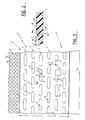
- - Fig. 1 is a fragmentary plan view of the signalling structure in question, mounted to the pavement of an underground railway station in the area facing the rails;
- - Fig. 2 is a cross sectional view of the signalling structure shown in Fig. 1;
- - Fig. 3 is an enlarged sectional view of a detail of the signalling structure of the invention.
- With reference to the drawings, a structure for signalling obstacles and dangerous areas to people unable to seen in accordance with the present invention, has been generally identified by
reference numeral 1. - The
signalling structure 1 essentially comprises at least a plate-like element 2 laid in coplanar relation with afloor 3, in a region close to the obstacle or the dangerous area to be signalled. - In the example shown by way of example only in the accompanying figures, the plate-
like element 2 is fastened, for example by means of glue or adhesive, to the under-paving 4 of anunderground railway platform 5 and extends along anend side 5a of the platform itself, in front of the rails (not shown). The remaining surface of the under-paving 4 is coated with thefloor 3 which, in the example shown, consists of conventional plate-like elements made of molded elastomeric material provided at the upper part thereof withsurface projections 3a of circular configuration, homogeneously distributed in side by side relation. - The plate-
like element 2, preferably made of molded elastomeric material has a width, identified by "A" in Fig. 1, ranging from 300 mm to 600 mm. Homogeneously distributed on onesurface 2a of the plate-like element 2 is a plurality ofsurface projections 6 having a substantially elongated configuration extending transversely to the user's advance direction towards the obstacle or dangerous area to be signalled, in che case shown towards theend side 5a of theplatform 5. Thesurface projections 6 are consecutively aligned so as to define a number ofrows 7 disposed parallelly in side by side relation, with a constant transverse gap therebetween which is identified by "B" in the accompanying figures and is preferably in the range of 70 to 90 mm. - The configuration of each
surface projection 6 exhibits two parallel rectilinear edges 8 extending at right angles to the advance direction of the user towards the obstacle or dangerous area, which edges are joined to each other by two semicircular end portions 9. The overall length of eachsurface projection 6 marked by "C" in Fig. 1, is preferably in the range of 95 to 115 mm. The width, identified by "D", of eachprojection 6 preferably ranges between 25 mm and 35 mm and preferably it is so conceived that a 2:3 ratio exists between the transverse gap "B" separating therows 7 and the projection width "D". - As clearly shown in Fig. 1, the
surface projections 6 of each row are homogeneously distributed according to a constant longitudinal spacing identified by "E", the value of which is comprised between 115 mm and 145 mm. - In addition, the
surface projections 6 of eachrow 7 are offset with respect to thesurface projections 7 belonging to thecontiguous row 7 by an amount corresponding to half their longitudinal spacing "E". - Each
surface projection 6 has anupper surface 6a located at a height "F" of 2 to 5 mm from theupper surface 2a of the plate-like element 2. As is apparent from Fig. 3, theupper surface 6a of thesurface projection 6 is joined to theupper surface 2a of the plate-like element 2 by two arcs of acircle circles - Advantageously, as can be readily seen from Fig. 2, the height "F" of the
surface projections 6 belonging to thedifferent rows 7 becomes increasingly greater as the danger area or the signalled obstacle, in this case theend side 5a of theplatform 5, comes closer. - In a preferred embodiment the projections of the two first rows are 3 mm in height and the projections of the following rows are 4 mm high.
- The plate-
like element 2 can also be partly or completely coloured in a showing up hue in order to facilitate also people which are not completely unable to see. - The operating features of the signalling structure according to the invention described above mainly as regards structure, can be readily understood.
- The presence of the
surface projections 6 gives the plate-like element 2 a surface configuration which can be immediately recognized to the touch by a person unable to see when he/she while walking towards the obstacle or the signalled area, reaches thesignalling structure 1. - Advantageously, the elongated configuration and the orientation of the
surface projections 6 also inform the blind person about the location and disposition of the obstacle or signalled dangerous area. In greater detail, the blind person will be able to know in advance that he/she will meet the obstacle or signalled area if he/she goes on walking in a direction perpendicular to the orientation of thesurface projections 6. - The progressive variation in height of the
surface projections 6 also informs the person unable to see about his/her progressive moving close to or apart from the signalled area while crossing thesignalling structure 1. - The present invention attains the intended purposes.
- It will be recognized in fact that the signalling structure of the invention is capable of giving clear and readily recognizable information to people unable to see, adapted to warn them of the presence of an obstacle or any danger situation. In this connection attention must be drawn to the fact that the specified structure features and size ratios relative to the described structure can ensure the immediate recognition of the signalling structure on the part of a blind person who meets it while walking along the
floor 3. - In addition, it is also pointed out that the signalling structure of the invention can be made at very reduced costs and can be easily installed even onto existing pavings.
- It will be also recognized that although the signalling structure in question has been specifically conceived for people unable to see or at all events having serious sight problems, it does not create any inconvenience to the public in the areas in which it is installed.
- Obviously modifications and variations can be made to the invention as conceived, all of them falling within the scope of the inventive idea characterizing it.
Claims (13)
1. A structure for signalling obstacles and dangerous areas to people unable to see, characterized in that it comprises at least a plate-like element (2) set in coplanar relation with a paving or floor (3), adjacent the obstacle to be signalled and provided at the upper part thereof with a plurality of surface projections (6) of substantially elongated configuration and homogeneously distributed transversely to the advance direction of the user towards the signalled obstacle.
2. A structure according to claim 1, characterized in that said surface projections (6) are arranged in alignment so as to form a plurality of parallel rows disposed in side by side relation, with a predetermined transverse gap "B" therebetween and each of them exhibiting the respective projections (6) disposed according to a predetermined longitudinal spacing "E" and offset relative to the surface projections (6) belonging to the contiguous row (7) by an amount equal to half their longitudinal spacing "E".
3. A structure according to claim, 1, characterized in that the configuration of each of said surface projections exhibits two parallel rectilinear edges (8) extending transversely to the user's advance direction towards the signalled obstacle and joined to each other by two semicircular end portions (9).
4. A structure according to claim 2, characterized in that said rows forming the surface projections (6) are mutually spaced apart from each other by a transverse gap "B" in the range of 70 to 90 mm.
5. A structure according to claim 2, characterized in that said longitudinal spacing "E" ranges between 115 mm and 145 mm.
6. A structure according to claim 1, characterized in that each surface projection (6) has a length "C" comprised between 95 mm and 115 mm.
7. A structure according to claim 1, characterized in that each surface projection (6) has a width "D" in the range of 25 to 35 mm.
8. A structure according to claim 2, characterized in that the ratio between the transverse gap "B" and the width "D" of each surface projection (6) has a value of 2:3.
9. A structure according to claim 1, characterized in that each surface projection (6) has a flat upper surface (6a) joined to the upper surface (2a) of the plate-like element (2) by two arcs of circles (10a, 10b) extending consecutively according to a substantially sinusoidal extension.
10. A structure according to claim 9, characterized in that said arcs of circles (10a, 10b) have a radius "G" of 6 to 9 mm.
11. A structure according to claim 1, characterized in that each surface projection (6) has a height "F" of 2 to 5 mm.
12. A structure according to claim 2, characterized in that the surface projections (6) belonging to the different rows (7) have an increasingly greater height "F" as they approach the signalled obstacle.
13. A structure according to claim 1, characterized in that said plate-like element (2) has an overall width "A" in the range of 300 to 600 mm.
Applications Claiming Priority (2)
| Application Number | Priority Date | Filing Date | Title |
|---|---|---|---|
| IT2219889 | 1989-10-30 | ||
| IT02219889A IT1237137B (en) | 1989-10-30 | 1989-10-30 | STRUCTURE FOR THE SIGNALING OF OBSTACLES AND DANGEROUS AREAS TO THE BLIND |
Publications (1)
| Publication Number | Publication Date |
|---|---|
| EP0425901A1 true EP0425901A1 (en) | 1991-05-08 |
Family
ID=11192932
Family Applications (1)
| Application Number | Title | Priority Date | Filing Date |
|---|---|---|---|
| EP90119952A Withdrawn EP0425901A1 (en) | 1989-10-30 | 1990-10-18 | Tactile signalling structure for sight disabled people incorporated in conventional paving |
Country Status (4)
| Country | Link |
|---|---|
| EP (1) | EP0425901A1 (en) |
| JP (1) | JPH03206203A (en) |
| CA (1) | CA2028727A1 (en) |
| IT (1) | IT1237137B (en) |
Cited By (9)
| Publication number | Priority date | Publication date | Assignee | Title |
|---|---|---|---|---|
| DE9105822U1 (en) * | 1990-05-22 | 1991-09-19 | Brummert, Klaus, 2000 Hamburg | Pavement slab with profiled tread |
| EP0945549A3 (en) * | 1998-03-25 | 2000-11-08 | Antonius Jacob Grahmbeek | Method for applying guidelines for visually handicapped persons, and a mould adapted for the application of the method |
| ES2157796A1 (en) * | 1998-12-30 | 2001-08-16 | Ferrer Cesar Gonzalez | Road safety device used by blind people when walking in urban areas. |
| US7779581B2 (en) | 2007-05-09 | 2010-08-24 | Ada Solutions, Inc. | Replaceable wet-set tactile warning surface unit and method of installation and replacement |
| US8920066B1 (en) | 2011-01-12 | 2014-12-30 | Tuf-Tite, Inc. | Tactile sidewalk surface |
| CN106245876A (en) * | 2015-06-10 | 2016-12-21 | 桑波田设计所株式会社 | Visually impaired person guides by floor system and construction method, guiding floor tile and the manufacture method of warning floor tile |
| CN111113655A (en) * | 2019-12-27 | 2020-05-08 | 中铁十八局集团北京工程有限公司 | Heat preservation and moisture preservation device for concrete |
| US10920378B2 (en) | 2018-01-19 | 2021-02-16 | Tuf-Tite, Inc. | Stamped steel detectable warning tile and method of manufacture |
| JP2021134514A (en) * | 2020-02-26 | 2021-09-13 | 学校法人近畿大学 | Guidance floor mat and guidance line using the same |
Citations (5)
| Publication number | Priority date | Publication date | Assignee | Title |
|---|---|---|---|---|
| US4620816A (en) * | 1984-11-15 | 1986-11-04 | Kupfer Jeffrey H | Bipedal guidance system and method |
| FR2590481A1 (en) * | 1985-11-22 | 1987-05-29 | Gerland | Relief coating product intended in particular for touch signs for the blind or for people suffering from amblyopia |
| US4715743A (en) * | 1986-06-13 | 1987-12-29 | Schmanski Donald W | Mobility guide tile for visually handicapped |
| DE8802560U1 (en) * | 1987-03-02 | 1988-05-05 | Mondo Rubber S.p.A., Diano d'Alba, Cuneo | Floor covering |
| GB2221234A (en) * | 1988-07-27 | 1990-01-31 | Univ Nottingham | Grooved paving slabs |
-
1989
- 1989-10-30 IT IT02219889A patent/IT1237137B/en active IP Right Grant
-
1990
- 1990-10-18 EP EP90119952A patent/EP0425901A1/en not_active Withdrawn
- 1990-10-29 CA CA002028727A patent/CA2028727A1/en not_active Abandoned
- 1990-10-30 JP JP2293504A patent/JPH03206203A/en active Pending
Patent Citations (5)
| Publication number | Priority date | Publication date | Assignee | Title |
|---|---|---|---|---|
| US4620816A (en) * | 1984-11-15 | 1986-11-04 | Kupfer Jeffrey H | Bipedal guidance system and method |
| FR2590481A1 (en) * | 1985-11-22 | 1987-05-29 | Gerland | Relief coating product intended in particular for touch signs for the blind or for people suffering from amblyopia |
| US4715743A (en) * | 1986-06-13 | 1987-12-29 | Schmanski Donald W | Mobility guide tile for visually handicapped |
| DE8802560U1 (en) * | 1987-03-02 | 1988-05-05 | Mondo Rubber S.p.A., Diano d'Alba, Cuneo | Floor covering |
| GB2221234A (en) * | 1988-07-27 | 1990-01-31 | Univ Nottingham | Grooved paving slabs |
Cited By (10)
| Publication number | Priority date | Publication date | Assignee | Title |
|---|---|---|---|---|
| DE9105822U1 (en) * | 1990-05-22 | 1991-09-19 | Brummert, Klaus, 2000 Hamburg | Pavement slab with profiled tread |
| EP0945549A3 (en) * | 1998-03-25 | 2000-11-08 | Antonius Jacob Grahmbeek | Method for applying guidelines for visually handicapped persons, and a mould adapted for the application of the method |
| ES2157796A1 (en) * | 1998-12-30 | 2001-08-16 | Ferrer Cesar Gonzalez | Road safety device used by blind people when walking in urban areas. |
| US7779581B2 (en) | 2007-05-09 | 2010-08-24 | Ada Solutions, Inc. | Replaceable wet-set tactile warning surface unit and method of installation and replacement |
| US8028491B2 (en) | 2007-05-09 | 2011-10-04 | Ada Solutions, Inc. | Replaceable wet-set tactile warning surface unit and method of installation and replacement |
| US8920066B1 (en) | 2011-01-12 | 2014-12-30 | Tuf-Tite, Inc. | Tactile sidewalk surface |
| CN106245876A (en) * | 2015-06-10 | 2016-12-21 | 桑波田设计所株式会社 | Visually impaired person guides by floor system and construction method, guiding floor tile and the manufacture method of warning floor tile |
| US10920378B2 (en) | 2018-01-19 | 2021-02-16 | Tuf-Tite, Inc. | Stamped steel detectable warning tile and method of manufacture |
| CN111113655A (en) * | 2019-12-27 | 2020-05-08 | 中铁十八局集团北京工程有限公司 | Heat preservation and moisture preservation device for concrete |
| JP2021134514A (en) * | 2020-02-26 | 2021-09-13 | 学校法人近畿大学 | Guidance floor mat and guidance line using the same |
Also Published As
| Publication number | Publication date |
|---|---|
| IT8922198A0 (en) | 1989-10-30 |
| JPH03206203A (en) | 1991-09-09 |
| IT1237137B (en) | 1993-05-24 |
| IT8922198A1 (en) | 1991-04-30 |
| CA2028727A1 (en) | 1991-05-01 |
Similar Documents
| Publication | Publication Date | Title |
|---|---|---|
| US5775835A (en) | Embedment tiles for pedestrian platforms and walkways | |
| CA2148070C (en) | Methods for producing detectible warnings on surfaces and products thereof | |
| EP0425901A1 (en) | Tactile signalling structure for sight disabled people incorporated in conventional paving | |
| US8082872B2 (en) | Detectable guidance markers for tactile navigation, including indicia of obstacle presence, type, dimensions, direction, and/or proximity | |
| US6709191B1 (en) | Tactile indicators for the visually impaired and method of installation thereof | |
| GB1591521A (en) | Roadway speed warning device | |
| EP0945549B1 (en) | Method for applying guidelines for visually handicapped persons, and a mould adapted for the application of the method | |
| US20080107481A1 (en) | Tactile directional tiles for pedestrians | |
| US20070042159A1 (en) | Elastic floor mat | |
| US7423552B2 (en) | “Warning Bump” traffic safety device | |
| Bentzen et al. | Impact of curb ramps on the safety of persons who are blind | |
| JP4179466B2 (en) | Elastic floor mats | |
| US6202587B1 (en) | Method and apparatus for warning individuals of unsafe zones | |
| CA2032532C (en) | Tiles for pedestrian platforms and walkways | |
| DE19500176A1 (en) | Marker for hazardous points and locations | |
| WO1994004757A1 (en) | Marking system for pedestrian crossings | |
| WO2001057341A1 (en) | Detectable warning and wayfinding system for persons with disabilities | |
| GB2221234A (en) | Grooved paving slabs | |
| CA2092367A1 (en) | Tiles for pedestrian platforms and walkways | |
| WO1994004757A9 (en) | Marking system for pedestrian crossings | |
| JPH0754330Y2 (en) | Walking guidance block for the visually impaired | |
| DE19935702A1 (en) | Modular railway station platform made of prefabricated pieces of concrete | |
| JP3735089B2 (en) | Walking guide structure for visually handicapped and guide for use in this | |
| JP2592888Y2 (en) | Sidewalk block board | |
| SU1046379A1 (en) | Pavement slab |
Legal Events
| Date | Code | Title | Description |
|---|---|---|---|
| PUAI | Public reference made under article 153(3) epc to a published international application that has entered the european phase |
Free format text: ORIGINAL CODE: 0009012 |
|
| AK | Designated contracting states |
Kind code of ref document: A1 Designated state(s): AT BE CH DE DK ES FR GB GR LI LU NL SE |
|
| 17P | Request for examination filed |
Effective date: 19920113 |
|
| 17Q | First examination report despatched |
Effective date: 19930722 |
|
| STAA | Information on the status of an ep patent application or granted ep patent |
Free format text: STATUS: THE APPLICATION IS DEEMED TO BE WITHDRAWN |
|
| 18D | Application deemed to be withdrawn |
Effective date: 19931202 |