EP0425377A1 - Process and apparatus for moulding building elements - Google Patents
Process and apparatus for moulding building elements Download PDFInfo
- Publication number
- EP0425377A1 EP0425377A1 EP90403002A EP90403002A EP0425377A1 EP 0425377 A1 EP0425377 A1 EP 0425377A1 EP 90403002 A EP90403002 A EP 90403002A EP 90403002 A EP90403002 A EP 90403002A EP 0425377 A1 EP0425377 A1 EP 0425377A1
- Authority
- EP
- European Patent Office
- Prior art keywords
- mold
- block
- walls
- molding
- forming
- Prior art date
- Legal status (The legal status is an assumption and is not a legal conclusion. Google has not performed a legal analysis and makes no representation as to the accuracy of the status listed.)
- Withdrawn
Links
Images


Classifications
-
- B—PERFORMING OPERATIONS; TRANSPORTING
- B28—WORKING CEMENT, CLAY, OR STONE
- B28B—SHAPING CLAY OR OTHER CERAMIC COMPOSITIONS; SHAPING SLAG; SHAPING MIXTURES CONTAINING CEMENTITIOUS MATERIAL, e.g. PLASTER
- B28B7/00—Moulds; Cores; Mandrels
- B28B7/22—Moulds for making units for prefabricated buildings, i.e. units each comprising an important section of at least two limiting planes of a room or space, e.g. cells; Moulds for making prefabricated stair units
-
- E—FIXED CONSTRUCTIONS
- E04—BUILDING
- E04G—SCAFFOLDING; FORMS; SHUTTERING; BUILDING IMPLEMENTS OR AIDS, OR THEIR USE; HANDLING BUILDING MATERIALS ON THE SITE; REPAIRING, BREAKING-UP OR OTHER WORK ON EXISTING BUILDINGS
- E04G11/00—Forms, shutterings, or falsework for making walls, floors, ceilings, or roofs
- E04G11/02—Forms, shutterings, or falsework for making walls, floors, ceilings, or roofs for rooms as a whole by which walls and floors are cast simultaneously, whole storeys, or whole buildings
Definitions
- the present invention relates generally to a method of molding a building block, for example of concrete, as well as to a device for implementing this method.
- This invention applies, for example, to the production of premises for residential or office use.
- the present invention aims to provide a method of molding a building block, for example concrete, and a device for its implementation, which allow the realization "in situ" of building blocks both simple, solid, inexpensive to produce and advantageously defining a habitable space.
- the subject of the present invention is a method of molding a building block constituted by a plate from which projecting elements are perpendicular or not, this method consisting in installing a mold with pivoting walls, at a location where said block must be permanently installed; lifting the mold cavity from the mold relative to a transport frame for this mold; unfolding and blocking said pivoting walls so as to form the molding cavity delimiting the contour of the plate and of the bearing elements of the block; optionally adjusting, in at least one horizontal and vertical direction, said mold cavity relative to the transport frame; pouring a molding material, for example concrete, into the molding cavity; folding the pivoting walls back to their initial position to release the plate and the load-bearing elements of the solidified block; to lower the mold cavity to detach it from the solidified block; and extracting the mold from the solidified block by passage between the load-bearing elements of said block.
- the walls are unfolded along a substantially horizontal axis to form the plate of the block, and the pivoting walls are unfolded along a substantially vertical axis to bring them closer to one another in order to define in the molding cavity part of this cavity which delimits the bearing elements of the block.
- This method is further characterized in that, after extraction of the mold from the solidified building block, the mold is juxtaposed with this block so that at least two walls pivoting along the above-mentioned substantially vertical axis enclose at least one of the carrier elements of said previously solidified block, then a second building block is molded adjacent to the first and having at least one common carrier element with the first block.
- the invention also relates to a molding device for implementing the method meeting the above characteristics, this device being constituted by a transportable mold comprising a molding cavity with articulated walls and means of transport and positioning of the mold relative to the ground.
- the mold comprises a molding cavity mounted relatively mobile on a chassis comprising on the one hand a substantially horizontal upper wall forming a receptacle for molding material such as concrete, and provided with flaps forming flaps articulated along a substantially horizontal axis and d secondly a plurality of double walls capable of pivoting along a substantially vertical axis and communicating with said upper wall forming a receptacle in the unfolded position thereof to allow the molding of a building block constituted by a plate comprising load-bearing elements protruding from this plateau.
- This device is further characterized in that the aforementioned chassis supports at least one carriage, coupled to the upper part forming the mold receptacle by articulated arms to allow the relative displacement of the molding cavity relative to the chassis.
- this device is characterized in that between the aforementioned carriage and the mold chassis is provided a second carriage movable relative to the first carriage in a direction orthogonal thereto.
- this device comprises formwork elements completing the above-mentioned double walls in the lower part of the mold.
- blocking means such as for example jacks, keep the flaps and the aforementioned double walls of the mold in the unfolded or folded position.
- This device is further characterized in that the mold is equipped with wheels and supports suitable means supply and treatment of concrete connected to an energy source, such as for example, solar collectors.
- the chassis is supported by several seats forming air cushions.
- Each seat forming an air cushion is fixed to the chassis by means of a ball-joint element.
- each element forming a ball joint consists of an upright or the like, secured to the chassis and swiveling in a housing secured to each seat.
- the seats forming air cushions are for example four in number, and are fixed permanently or removably to the chassis.
- a molding device which is essentially constituted by a transportable mold 1 which comprises a frame 5 and a molding cavity 2.
- this transportable mold 1 has at its upper part the molding cavity 2 for receiving concrete or any other moldable material.
- This molding cavity 2 has at its top an upper wall 3 on which are laterally mounted, pivoting about axes 4a and 4b parallel to the two longitudinal edges of the upper wall 3, two walls forming flap 3a and 3b.
- the longitudinal axes 4a and 4b extend substantially horizontally to allow the flaps 3a and 3b to pivot towards a position called “molding position", that is to say a position raised, so that the upper surface of the flaps is in a horizontal plane comprising the wall 3, as can be seen on the left side of FIG. 1.
- the flaps 3a and 3b can also be folded against the mold towards a so-called position "transport position" of this mold, as illustrated on the right-hand side of FIG. 1.
- the mold cavity 2 is mounted movably on the frame 5 which will be described later.
- Locking members 6a and 6b serve to selectively lock the flaps 3a and 3b in the upper molding or folded down transport position. These locking members 6a and 6b are respectively pivotally mounted at their upper end under the flaps 3a and 3b and at their lower end on the chassis 5.
- the molding cavity 2 has four double walls 7a, 7b pivotally mounted on the frame 5 so that it can be selectively unfolded in the molding position ( Figure 3) or folded against the frame 5 in the transport (figure 2).
- These double walls 7a, 7b are constituted by an external flap 7a and an internal flap 7b.
- These flaps 7a and 7b are each articulated about a vertical axis 8 and form in the molding position, that is to say in the contiguous position, the vertical and lower part of the molding cavity 2.
- the space between the flaps 7a and 7b communicates in the upper part with the upper part of the molding cavity 2 formed by the upper wall 3 and the flaps 3a and 3b described above.
- Locking latches make it possible to immobilize the double walls 7a, 7b in the molding or transport position of the mold 1.
- the horizontal upper part of the molding cavity 2 formed by the walls 3, 3a and 3b has on certain parts of its periphery flanges 2b corresponding to the thickness of the upper horizontal part of the building block. to mold.
- longitudinal and transverse grooves 10 are formed in the horizontal upper part of the molding cavity 2 to form reinforcing ribs on the corresponding part of the building block to be molded.
- the frame 5 on which the molding cavity 2 is mounted has an upper support 11 as can be seen in FIG. 3, which is fixed, for example by welding, to the upper wall 3 of the molding cavity 2.
- This support 11 has at its front and rear ends (FIGS. 2 and 3), support beams 12 on which the double walls 7a, 7b of the molding cavity 2 are articulated as described above.
- the upper support 11 is itself supported by a mechanism for adjusting the height of the molding cavity 2 constituted by articulated arms 13 forming compasses. These compasses are mounted articulated between, on the one hand the upper support 11 and on the other hand a carriage 14 which will be described below.
- the compasses 13, the carriage 14 and the upper support 11 together form deformable polygons allowing the height adjustment of the molding cavity relative to the carriage 14.
- the carriage 14 is provided with rollers 16 guided in rails 17 forming part of a second carriage 18 arranged under the first carriage 14.
- the rollers 16 thus guided allow the longitudinal displacement of the carriage 14 relative to the second carriage 18 which will be described now. It will be specified that the first carriage 14 can roll on the second carriage 18 which can itself roll on the lower part or base 21 of the chassis 5.
- the carriage 18 has rollers 19 guided in rails 20 integral with the base 21 and orthogonal to the rails 17, so that the carriage 18 can move in a direction perpendicular to the direction of movement of the carriage 14.
- wheels have been shown fixed under the base 21 of the chassis 5 and allowing the transport by rolling of the whole of the molding device according to the invention.
- the base 21 of the chassis 5 is further equipped with a system of retractable crutches 24 making it possible to stabilize the mold 1 in a fixed position relative to the ground.
- various pieces of equipment can be mounted on the mold 1, such as a concrete pump, a vibrator or a system for heating the molding cavity 2.
- the molding device which has just been described above makes it possible to manufacture building blocks B such as that clearly visible in FIG. 15 and comprising in particular a horizontal plate P and vertical support elements E protruding, according to the example of embodiment shown, perpendicular to the plate P and intended to rest, for example, on the ground.
- the mold 1 is moved using the wheels 22 and 23, the walls of which are closed in the transport position up to the location S of the building, represented by dotted lines, where the building block B will be molded
- this location S is located on an already existing construction, such as for example another solidified building block B.
- a foundation such as a concrete slab or a foundation under each vertical support element at the location S chosen to rest the building block that we want to mold.
- the crutches 24 are placed so as to stabilize the mold 1 relative to the ground, as is sees well in Figure 5, and thus avoid unwanted movement during subsequent molding operations.
- the first walls placed in the molding position are the flaps 3a and 3b. To achieve this, these flaps are raised to a substantially horizontal position using jacks 6a and 6b ( Figure 1) which also block the flaps.
- the four double walls 7a, 7b forming the lower part of the cavity 2 and serving to mold the support elements E of the building block B are then unfolded as seen in FIG. 7 in the molding position.
- the outer flaps 7a are pivoted about the axes 8 from their folded position against the ends of the chassis 5 to a position of coincidence with the flaps 3a and 3b.
- the interior flaps 7b are pivoted about their axes 8 from their folded position between the frame 5 to a position of contact with the exterior flaps to define with them a molding space communicating with the upper part of the molding cavity 2 and allowing the molding in a single block of the support elements E and of the plate P of the block.
- the internal flaps 7b and that the external flaps 7a are, in the molding position, immobilized by latches (not shown).
- the lifting operation is carried out by deforming, using a crank (not shown), the compasses constituted by the articulated arms 13 in the direction indicated by the arrows H in FIG. 8.
- the carriages 14 and 18 are immobilized relative to the base 21 of the chassis 5 using, for example, brakes (not shown) blocking the rotation of the rollers 16 and 19.
- a concrete pouring operation can then be carried out, as shown very schematically in FIG. 10, which concrete fills all the space defined by the double walls 7a, 7b, the wall 3, the flaps 3a, 3b, the flanges 2b and the forms 25 and 26.
- Reinforcement reinforcements (not shown) can be placed in the molding cavity 2 before the latter is filled with concrete up to the top of the flanges 2b.
- the concrete can then be vibrated inside the molding cavity 2 so as to make it more homogeneous.
- a vibrator of the type used in construction can be installed, for example, on the molding cavity 2.
- a heating system for the mold cavity 2 which may for this purpose include electrical resistors arranged near the locations to be heated from the mold 1 and integral with this mold so as to keep the concrete block B frost-free or even to accelerate its solidification.
- Solar water collectors (not shown) can also be placed near the mold 1 so as to advantageously provide the necessary heat.
- All mold equipment requiring electric current supply can advantageously be supplied with current using autonomous means (not shown).
- the formwork elements 25 and 26 are then disassembled, as can be seen in FIG. 11.
- the double walls 7a, 7b are opened. so as to release the supporting elements E from the building block B, as can be seen in FIG. 12.
- the double walls 7a and 7b are folded back by pivoting the flaps 7a and 7b around their axes 8 until '' they are placed against the frame 5 of the mold 1.
- FIG. 13 shows the operation of lowering the molding cavity 2 relative to the chassis 5. This operation is carried out by acting on the articulated arms 13 of the compasses in the opposite direction to that previously described for the lifting operation .
- the arrow A in FIG. 13 illustrates the deformation of the articulated arms 13 and the lowering of the molding cavity 2.
- it is essential to lower the cavity 2 by a height such that the wall 3 and the flaps 3a and 3b are lower than the lower part of the ribs of the plate P resulting from the molding of the concrete in the grooves 10.
- the mold 1 is extracted by rolling it between the bearing elements E of the block of construction B.
- a building block B which alone can constitute the framework of a building such as, for example, a detached house, it being understood that it will suffice to closing, with prefabricated elements for example, the lateral openings delimited by the load-bearing elements E.
- this method and this device also advantageously make it possible to produce a building block B which can serve as a reference for the positioning of the mold 1 in order to proceed with a new molding operation so as to form, for example, a building made up of several building blocks B placed side by side.
- the mold 1 is juxtaposed with a building block B previously molded.
- the procedure for adjusting the position of the mold cavity 2 relative to the frame 5 is carried out in the same way as described above, so as to place the mold cavity 2 in a position such that one can enclose one of the carrier elements E of the building block B already solidified between the exterior flaps 7a and interior 7b of one of the double walls 7a, 7b.
- the different walls of the mold 1 are then installed in the molding position as illustrated in FIGS. 4 to 7.
- a second building block is molded adjacent to the first solidified block and therefore having a supporting element E in common with the first block.
- FIGS. 16 to 18 represent another embodiment of the support and displacement means on the floor of the device according to this invention, and which bear the same references to designate the common elements.
- Each seat 40 is integral with a frame or the like 30 connected to the support 11 by means of the mechanism with articulated arms 13 allowing the height adjustment of the molding cavity.
- each seat forming an air cushion can be fixed permanently or removably to the chassis 5.
- each seat forming an air cushion 40 is constituted by a plate 42 under which a skirt 43 is fixed.
- the skirt 43 rests itself on a support plane of the mold 1, such as for example the ground.
- a flexible pipe 44 for supplying compressed air is fixed on the plate 42 and communicates with a chamber 45 formed in this plate.
- the bottom wall of the plate 42 has a plurality of holes 46 which connect the chamber 45 to the space delimited by the skirt 43, between the plate 42 and the bearing plane of the mold.
- Each support plate 42 is articulated on the frame 30 by means of a ball-joint element 50.
- This element 50 comprises an upright 51 or the like, which is fixed, for example by welding, to the frame 30, and which extends substantially vertically from the lower part thereof. It will be specified here that the seats forming air cushions can also be detachably fixed to the chassis 5.
- the lower end of the upright 51 has the shape of a hemisphere 52 which is connected to the upright by a portion of reduced section 53.
- a housing 41 is mounted with clearance on the upright 51 at the portion of reduced section 53 which passes through a bore 41b of the upper wall 41a of the housing 41.
- the hemisphere 52 can come into contact with the lower wall 41c of the housing, thanks to the mounting clearance of the part 53 in the bore 51b.
- the lower wall 41c of the housing is fixed to the support plate 42 to thereby produce a swiveling connection.
- the air cushion 40 can automatically adapt to the irregularities of the surface on which the mold 1 rests to facilitate its movement, as for example in the case where it is desired to move the mold on an inclined plane. It is thus possible to avoid any recourse to an additional displacement system such as a crane, when it is desired to load the mold on a vehicle for example.
- the mold 1 is equipped with four seats forming air cushions 40 arranged in the vicinity of the four corners of the frame 30, which is for example rectangular.
- Each air cushion 40 is connected, by through its supply line 44 to a pressure distributor 60.
- the pressure distributor 60 is itself connected by a flexible conduit 61 to an internal compressor shown schematically at 70 in FIG. 17.
- This compressed air supply system has two main advantages. First of all thanks to the distributor 60, it is possible to balance the pressures in the air cushions 40 to give the chassis 5 perfect stability. Then, it is possible to use a compressor of the type of those commonly used on construction sites, this compressor can also be used for other purposes than feeding the air cushions, for example to vibrate the material to be molded.
- this block can have a polygonal or other shape and include supporting elements E perpendicular or not at the P stage of the block.
Abstract
Description
La présente invention se rapporte d'une manière générale à un procédé de moulage d'un bloc de construction, par exemple en béton, ainsi qu'à un dispositif pour la mise en oeuvre de ce procédé.The present invention relates generally to a method of molding a building block, for example of concrete, as well as to a device for implementing this method.
Cette invention s'applique, par exemple, à la réalisation de locaux à usage d'habitation ou de bureaux.This invention applies, for example, to the production of premises for residential or office use.
On connaît des moules formés à l'aide de parois articulées se refermant par pivotement autour d'un axe de manière à délimiter une cavité de moulage pouvant s'ouvrir après solidification de l'objet moulé. Toutefois, ce type de moule n'est que rarement employé pour la fabrication de blocs de construction "in situ", c'est-à-dire à l'emplacement même où les blocs seront érigés pour construire un bâtiment.There are known molds formed using articulated walls which close by pivoting about an axis so as to delimit a molding cavity which can open after solidification of the molded object. However, this type of mold is only rarely used for the manufacture of building blocks "in situ", that is to say at the same location where the blocks will be erected to construct a building.
L'utilisation d'une telle technique pose en effet d'importants problèmes tant en ce qui concerne la conception du moule lui-même que l'exécution du moulage.The use of such a technique indeed poses significant problems both with regard to the design of the mold itself and the execution of the molding.
Ces problèmes sont d'autant plus difficiles à résoudre à partir du moment où il est souhaitable de mouler des blocs de construction ayant des dimensions importantes, ce qui permet une construction rapide du bâtiment à construire.These problems are all the more difficult to solve from the moment when it is desirable to mold building blocks having large dimensions, which allows rapid construction of the building to be constructed.
Jusqu'à présent, il était également difficile, particulièrement dans les pays en voie de développement, d'obtenir par moulage "in situ" des blocs de construction suffisamment grands et solides pour réaliser des locaux d'habitation, et cela en limitant la qualification de la main d'oeuvre et la matière nécessaire à cette réalisation.Until now, it has also been difficult, particularly in developing countries, to obtain, by "in situ" molding, building blocks large enough and solid to make living quarters, and this by limiting the qualification of the workforce and the material necessary for this realization.
Pour réunir tous ces avantages sans pour autant augmenter le coût du produit fini et pour permettre la réalisation de complexes d'habitation économiques, il est de plus souhaitable de pouvoir juxtaposer sur place des blocs de construction de façon à pouvoir occuper l'espace disponible le plus rationnellement possible.To combine all these advantages without increasing the cost of the finished product and to allow the realization of economic housing complexes, it is more desirable to be able to juxtapose on the building blocks so as to be able to occupy the available space the as rationally as possible.
Par conséquent, la présente invention a pour but de proposer un procédé de moulage d'un bloc de construction, par exemple en béton, ainsi qu'un dispositif pour sa mise en oeuvre, qui permettent la réalisation "in situ" de blocs de construction à la fois simples, solides, peu coûteux à produire et délimitant avantageusement un espace habitable.Therefore, the present invention aims to provide a method of molding a building block, for example concrete, and a device for its implementation, which allow the realization "in situ" of building blocks both simple, solid, inexpensive to produce and advantageously defining a habitable space.
A cet effet, la présente invention a pour objet un procédé de moulage d'un bloc de construction constitué par un plateau dont font saillie perpendiculairement ou non des éléments porteurs, ce procédé consistant à installer un moule avec parois pivotantes, à un emplacement où ledit bloc doit être définitivement installé ; à soulever la cavité de moulage du moule par rapport à un châssis de transport de ce moule ; à déplier et bloquer lesdites parois pivotantes de façon à former la cavité de moulage délimitant le contour du plateau et des éléments porteurs du bloc ; à ajuster éventuellement, suivant au moins une direction horizontale et verticale, ladite cavité de moulage par rapport au châssis de transport ; à couler une matière à mouler, par exemple du béton, à l'intérieur de la cavité de moulage ; à replier les parois pivotantes à leur position initiale pour dégager le plateau et les éléments porteurs du bloc solidifié ; à abaisser la cavité de moulage pour la détacher du bloc solidifié ; et à extraire le moule du bloc solidifié par passage entre les éléments porteurs dudit bloc.To this end, the subject of the present invention is a method of molding a building block constituted by a plate from which projecting elements are perpendicular or not, this method consisting in installing a mold with pivoting walls, at a location where said block must be permanently installed; lifting the mold cavity from the mold relative to a transport frame for this mold; unfolding and blocking said pivoting walls so as to form the molding cavity delimiting the contour of the plate and of the bearing elements of the block; optionally adjusting, in at least one horizontal and vertical direction, said mold cavity relative to the transport frame; pouring a molding material, for example concrete, into the molding cavity; folding the pivoting walls back to their initial position to release the plate and the load-bearing elements of the solidified block; to lower the mold cavity to detach it from the solidified block; and extracting the mold from the solidified block by passage between the load-bearing elements of said block.
On comprend déjà qu'après solidification du béton formant le bloc de construction, le moule est en quelque sorte replié à l'intérieur de ce bloc et en est extrait, par constraste avec les procédés classiques où ce sont les objets moulés qui sont retirés du moule.It is already understood that after solidification of the concrete forming the building block, the mold is somehow folded back inside this block and is extracted therefrom, by contrast with the conventional methods where it is the molded objects which are removed from the mold.
Suivant une autre caractéristique de ce procédé, on déplie suivant un axe sensiblement horizontal des parois pour former le plateau du bloc, et on déplie des parois pivotantes suivant un axe sensiblement vertical pour les rapprocher l'une de l'autre afin de définir dans la cavité de moulage une partie de cette cavité qui délimite les éléments porteurs du bloc.According to another characteristic of this process, the walls are unfolded along a substantially horizontal axis to form the plate of the block, and the pivoting walls are unfolded along a substantially vertical axis to bring them closer to one another in order to define in the molding cavity part of this cavity which delimits the bearing elements of the block.
Ce procédé est encore caractérisé en ce que, après extraction du moule hors du bloc de construction solidifié, on juxtapose le moule à ce bloc de façon qu'au moins deux parois pivotant suivant l'axe sensiblement vertical précité enserrent au moins l'un des éléments porteurs dudit bloc précédemment solidifié, puis on moule un deuxième bloc de construction adjacent au premier et possédant au moins un élément porteur commun avec le premier bloc.This method is further characterized in that, after extraction of the mold from the solidified building block, the mold is juxtaposed with this block so that at least two walls pivoting along the above-mentioned substantially vertical axis enclose at least one of the carrier elements of said previously solidified block, then a second building block is molded adjacent to the first and having at least one common carrier element with the first block.
L'invention vise encore un dispositif de moulage pour la mise en oeuvre du procédé répondant aux caractéristiques ci-dessus, ce dispositif étant constitué par un moule transportable comprenant une cavité de moulage avec des parois articulées et des moyens de transport et de positionnement du moule par rapport au sol.The invention also relates to a molding device for implementing the method meeting the above characteristics, this device being constituted by a transportable mold comprising a molding cavity with articulated walls and means of transport and positioning of the mold relative to the ground.
Ce dispositif est essentiellement caractérisé en ce que le moule comporte une cavité de moulage montée relativement mobile sur un châssis comportant d'une part une paroi supérieure sensiblement horizontale formant réceptacle pour de la matière à mouler telle que du béton, et munie de parois formant abattants articulées suivant un axe sensiblement horizontal et d'autre part une pluralité de doubles parois susceptibles de pivoter suivant un axe sensiblement vertical et de communiquer avec ladite paroi supérieure formant réceptacle en position dépliée de celle-ci pour permettre le moulage d'un bloc de construction constitué par un plateau comportant des éléments porteurs en saillie de ce plateau.This device is essentially characterized in that the mold comprises a molding cavity mounted relatively mobile on a chassis comprising on the one hand a substantially horizontal upper wall forming a receptacle for molding material such as concrete, and provided with flaps forming flaps articulated along a substantially horizontal axis and d secondly a plurality of double walls capable of pivoting along a substantially vertical axis and communicating with said upper wall forming a receptacle in the unfolded position thereof to allow the molding of a building block constituted by a plate comprising load-bearing elements protruding from this plateau.
Ce dispositif est encore caractérisé en ce que le châssis précité supporte au moins un chariot, attelé à la partie supérieure formant réceptacle du moule par des bras articulés pour permettre le déplacement relatif de la cavité de moulage par rapport au châssis.This device is further characterized in that the aforementioned chassis supports at least one carriage, coupled to the upper part forming the mold receptacle by articulated arms to allow the relative displacement of the molding cavity relative to the chassis.
De plus, ce dispositif est caractérisé en ce qu'entre le chariot précité et le châssis du moule est prévu un deuxième chariot mobile par rapport au premier chariot suivant une direction orthogonale à celui-ci.In addition, this device is characterized in that between the aforementioned carriage and the mold chassis is provided a second carriage movable relative to the first carriage in a direction orthogonal thereto.
Par ailleurs, ce dispositif comprend des éléments de coffrage complétant les doubles parois précitées en partie basse du moule.Furthermore, this device comprises formwork elements completing the above-mentioned double walls in the lower part of the mold.
On précisera encore ici que des moyens de blocage, tels que par exemple des vérins, maintiennent en position dépliée ou repliée les abattants et les doubles parois précitées du moule.It will also be specified here that blocking means, such as for example jacks, keep the flaps and the aforementioned double walls of the mold in the unfolded or folded position.
Ce dispositif est encore caractérisé en ce que le moule est équipé de roues et supporte des moyens appropriés d'alimentation et de traitement du béton reliés à une source d'énergie, telle que par exemple, des capteurs solaires.This device is further characterized in that the mold is equipped with wheels and supports suitable means supply and treatment of concrete connected to an energy source, such as for example, solar collectors.
Selon un mode de réalisation préféré du dispositif selon cette invention, le châssis est supporté par plusieurs assises formant coussins d'air.According to a preferred embodiment of the device according to this invention, the chassis is supported by several seats forming air cushions.
Chaque assise formant coussin d'air est fixée au châssis par l'intermédiaire d'un élément formant rotule.Each seat forming an air cushion is fixed to the chassis by means of a ball-joint element.
Suivant une autre caractéristique, chaque élément formant rotule est constitué par un montant ou analogue, solidaire du châssis et rotulant dans un boîtier solidaire de chaque assise.According to another characteristic, each element forming a ball joint consists of an upright or the like, secured to the chassis and swiveling in a housing secured to each seat.
Selon encore une autre caractéristique, les assises formant coussins d'air sont par exemple au nombre de quatre, et sont fixées à demeure ou de façon amovible au châssis.According to yet another characteristic, the seats forming air cushions are for example four in number, and are fixed permanently or removably to the chassis.
Mais d'autres caractéristiques et avantages de l'invention apparaîtront mieux dans la description détaillée qui suit et qui se réfère aux dessins annexés, donnés uniquement à titre d'exemple, et dans lesquels :
- La figure 1 est une vue en élévation et en coupe verticale du dispositif de montage selon l'invention avec l'une de ses parois supérieures formant abattant montrée en position dépliée et bloquée de moulage et une autre paroi supérieure repliée contre le châssis du moule en position de transport ;
- La figure 2 est une vue en coupe verticale suivant la ligne II-II de la figure 1 ;
- La figure 3 est une vue en section horizontale du dispositif dont les doubles parois sont illustrées en position de moulage ;
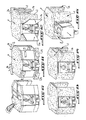
- Les figures 4 à 15 illustrent en perspective et schématiquement les phases successives de mise en oeuvre du dispositif de moulage et de fabrication d'un bloc de construction moulé à l'aide de ce dispositif ;
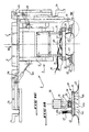
- La figure 16 est une vue en élévation du dispositif équipé d'une variante de support au sol de la cavité de moulage ;
- La figure 17 est une vue suivant la flèche VII de la figure 16 ; et
- La figure 18 est une vue agrandie d'un détail désigné en VIII de la figure 16.
- Figure 1 is an elevational view in vertical section of the mounting device according to the invention with one of its upper walls forming a flap shown in the unfolded and locked molding position and another upper wall folded against the chassis of the mold transport position;
- Figure 2 is a vertical sectional view along line II-II of Figure 1;
- Figure 3 is a horizontal sectional view of the device, the double walls of which are illustrated in the molding position;
- Figures 4 to 15 illustrate in perspective and schematically the successive phases of implementation of the molding device and manufacturing of a building block molded using this device;
- FIG. 16 is an elevation view of the device equipped with a variant support on the ground of the molding cavity;
- Figure 17 is a view along arrow VII of Figure 16; and
- FIG. 18 is an enlarged view of a detail designated in VIII of FIG. 16.
En se reportant aux figures 1 à 3, on voit un dispositif de moulage qui est essentiellement constitué par un moule transportable 1 qui comporte un châssis 5 et une cavité de moulage 2.Referring to FIGS. 1 to 3, we can see a molding device which is essentially constituted by a transportable mold 1 which comprises a
Comme on le voit bien sur la figure 1, ce moule transportable 1 comporte en sa partie supérieure la cavité de moulage 2 pour recevoir du béton ou une autre matière moulable quelconque. Cette cavité de moulage 2 comporte à son sommet une paroi supérieure 3 sur laquelle sont latéralement montées, pivotant autour d'axes 4a et 4b parallèles aux deux bords longitudinaux de la paroi supérieur 3, deux parois formant abattant 3a et 3b. Les axes longitudinaux 4a et 4b s'étendent de façon sensiblement horizontale pour permettre aux abattants 3a et 3b de pivoter vers une position dite "position de moulage", c'est-à-dire une position relevée, pour que la surface supérieure des abattants se trouve dans un plan horizontal comprenant la paroi 3, comme on le voit bien sur la partie gauche de la figure 1. Les abattants 3a et 3b peuvent également être rabattus contre le moule vers une position dite "position de transport" de ce moule, comme illustré sur la partie droite de la figure 1.As can be clearly seen in FIG. 1, this transportable mold 1 has at its upper part the molding cavity 2 for receiving concrete or any other moldable material. This molding cavity 2 has at its top an
La cavité de moulage 2 est montée mobile sur le châssis 5 qui sera décrit ultérieurement.The mold cavity 2 is mounted movably on the
Des organes de blocage 6a et 6b, visibles sur la figure 1 et tels que des vérins, servent à bloquer sélectivement les abattants 3a et 3b en position supérieure de moulage ou rabattue de transport. Ces organes de blocage 6a et 6b sont respectivement montés pivotants à leur extrémité supérieure sous les abattants 3a et 3b et à leur extrémité inférieure sur le châssis 5.Locking
On voit clairement sur les figures 2 et 3 que la cavité de moulage 2 comporte quatre doubles parois 7a, 7b montées pivotantes sur le châssis 5 pour pouvoir être sélectivement dépliées en position de moulage (figure 3) ou repliées contre le châssis 5 en position de transport (figure 2). Ces doubles parois 7a, 7b sont constituées par un volet extérieur 7a et un volet intérieur 7b. Ces volets 7a et 7b sont articulés chacun autour d'un axe vertical 8 et forment en position de moulage, c'est-à-dire en position jointive, la partie verticale et inférieure de la cavité de moulage 2. L'espace entre les volets 7a et 7b communique en partie haute avec la partie supérieure de la cavité de moulage 2 formée par la paroi supérieurs 3 et les abattants 3a et 3b décrits précédemment.It is clearly seen in Figures 2 and 3 that the molding cavity 2 has four
Afin de permettre aux volets extérieurs 7a de s'intercaler après repliement aux extrémités du châssis 5 (figure 3), ces volets 7a sont montés articulés sur ledit châssis par l'intermédiaire de biellettes telles que celles repérées en 9.In order to allow the
Quant aux volets intérieurs 7b des doubles parois 7a, 7b, ils sont repliables contre le châssis 5, entre les extrémités dudit châssis.As for the
Des loquets de blocage (non représentés) permettent d'immobiliser les doubles parois 7a, 7b en position de moulage ou de transport du moule 1.Locking latches (not shown) make it possible to immobilize the
Il est important de noter que la partie supérieure horizontale de la cavité de moulage 2 formée par les parois 3, 3a et 3b, comporte sur certaines parties de sa périphérie des rebords 2b correspondant à l'épaisseur de la partie horizontale supérieure du bloc de construction à mouler.It is important to note that the horizontal upper part of the molding cavity 2 formed by the
En outre, des rainures 10 longitudinales et transversales sont ménagées dans la partie supérieure horizontale de la cavité de moulage 2 pour former des nervures de renforcement sur la partie correspondante du bloc de construction à mouler.In addition, longitudinal and
Le châssis 5 sur lequel est montée la cavité de moulage 2 comporte un support supérieur 11 comme on le voit bien sur la figure 3, qui est fixé, par exemple par soudage, sur la paroi supérieure 3 de la cavité de moulage 2. Ce support 11 possède à ses extrémités avant et arrière (figures 2 et 3), des poutres 12 de support sur lesquelles sont articulées comme décrit plus haut les doubles parois 7a, 7b de la cavité de moulage 2.The
Le support supérieur 11 est lui-même soutenu par un mécanisme d'ajustement en hauteur de la cavité de moulage 2 constitué par des bras articulés 13 formant des compas. Ces compas sont montés articulés entre, d'une part le support supérieur 11 et d'autre part un chariot 14 qui sera décrit ci-après.The
Les compas 13, le chariot 14 et le support supérieur 11 forment ensemble des polygones déformables permettant le réglage en hauteur de la cavité de moulage par rapport au chariot 14.The compasses 13, the
Le chariot 14 est muni de roulettes 16 guidées dans des rails 17 faisant partie d'un deuxième chariot 18 agencé sous le premier chariot 14. Les roulettes 16 ainsi guidées permettent le déplacement longitudinal du chariot 14 par rapport au deuxième chariot 18 qui va être décrit maintenant. On précisera que le premier chariot 14 peut rouler sur le deuxième chariot 18 qui peut lui-même rouler sur la partie inférieure ou embase 21 du châssis 5.The
Le chariot 18 comporte des roulettes 19 guidées dans des rails 20 solidaires de l'embase 21 et orthogonaux aux rails 17, de sorte que le chariot 18, peut se déplacer selon une direction perpendiculaire à la direction de déplacement du chariot 14.The
On a montré en 22, 23 des roues fixées sous l'embase 21 du châssis 5 et permettant le transport par roulement de l'ensemble du dispositif de moulage selon l'invention.At 22, 23, wheels have been shown fixed under the
L'embase 21 du châssis 5 est en outre équipée d'un système de béquilles rétractables 24 permettant de stabiliser le moule 1 dans une position fixe par rapport au sol.The
Selon les besoins, divers équipements (non représentés) peuvent être montés sur le moule 1, comme par exemple une pompe à béton, un vibreur ou un système de chauffage de la cavité de moulage 2.Depending on requirements, various pieces of equipment (not shown) can be mounted on the mold 1, such as a concrete pump, a vibrator or a system for heating the molding cavity 2.
Le dispositif de moulage qui vient d'être décrit ci-dessus permet de fabriquer des blocs de constructions B tels que celui bien visible sur la figure 15 et comprenant notamment un plateau horizontal P et des éléments porteurs verticaux E faisant saillies, suivant l'exemple de réalisation représenté, perpendiculairement au plateau P et destinés à reposer, par exemple, sur le sol.The molding device which has just been described above makes it possible to manufacture building blocks B such as that clearly visible in FIG. 15 and comprising in particular a horizontal plate P and vertical support elements E protruding, according to the example of embodiment shown, perpendicular to the plate P and intended to rest, for example, on the ground.
Le fonctionnement du dispositif précédent sera décrit ci-après à l'aide des figures 3 à 15 où seules les pièces nécessaires à la compréhension sont représentées.The operation of the previous device will be described below with the aid of Figures 3 to 15 where only the parts necessary for understanding are shown.
Tout d'abrod, comme on le voit sur la figure 4, on déplace grâce aux roues 22 et 23 le moule 1 dont les parois sont refermées en position de transport jusqu'à l'emplacement S du bâtiment, représenté par des traits pointillés, où sera moulé le bloc de construction B.All abrod, as can be seen in FIG. 4, the mold 1 is moved using the
On peut très bien imaginer que cet emplacement S soit situé sur une construction déjà existante, comme par exemple un autre bloc de construction B solidifié. D'autre part, on pourra réaliser, pour des raisons d'hygiène et de stabilité, une fondation telle qu'une dalle de béton ou une fondation sous chaque élément porteur vertical à l'emplacement S choisi pour faire reposer le bloc de construction que l'on désire mouler.One can very well imagine that this location S is located on an already existing construction, such as for example another solidified building block B. On the other hand, it will be possible, for reasons of hygiene and stability, to create a foundation such as a concrete slab or a foundation under each vertical support element at the location S chosen to rest the building block that we want to mold.
Une fois le moule 1 disposé à l'emplacement S choisi, les béquilles 24 sont mises en place de façon à stabiliser le moule 1 par rapport au sol, comme on le voit bien sur la figure 5, et à ainsi éviter tout déplacement indésirable lors des opérations ultérieures du moulage.Once the mold 1 has been placed at the location S chosen, the
La mise à la position du moulage des parois formant la cavité de moulage 2 va maintenant être décrite en faisant référence aux figures 6 et 7.The placing of the walls forming the molding cavity 2 in the position of molding will now be described with reference to FIGS. 6 and 7.
Les premières parois mises en position de moulage sont les abattants 3a et 3b. Pour y parvenir, ces abattants sont soulevés jusqu'à une position sensiblement horizontale à l'aide des vérins 6a et 6b (figure 1) qui assurent également le blocage des abattants.The first walls placed in the molding position are the
On voit alors clairement sur la figure 6 que les rainures 10 et les rebords 2b forment, avec les abattants 3a et 3b et la paroi supérieure 3, la partie supérieure de la cavité de moulage 2.It is then clearly seen in FIG. 6 that the
Les quatre doubles parois 7a, 7b formant la partie inférieure de la cavité 2 et servant à mouler les éléments porteurs E du bloc de construction B sont alors dépliées comme on le voit sur la figure 7 dans la position de moulage. Pour ce faire, on fait pivoter autour des axes 8 les volets extérieurs 7a depuis leur position repliée contre les extrémités du châssis 5 jusqu'à une position de coincidence avec les abattants 3a et 3b. Puis, on fait pivoter les volets intérieurs 7b autour de leurs axes 8 depuis leur position rabattue entre le châssis 5 jusqu'à une position de contact avec les volets extérieurs pour définir avec ceux-ci un espace de moulage communiquant avec la partie supérieure de la cavité de moulage 2 et permettant le moulage en un seul bloc des éléments porteurs E et du plateau P du bloc. On observera que les volets intérieurs 7b et que les volets extérieurs 7a sont, en position de moulage, immobilisés par des loquets (non représentés).The four
Les opérations d'ajustement des positions longitudinale et transversale de la cavité de moulage 2 ainsi que l'opération de soulèvement de cette cavité de moulage 2 par rapport au châssis 5 seront décrites ci-après.The operations for adjusting the longitudinal and transverse positions of the molding cavity 2 as well as the lifting operation of this molding cavity 2 relative to the
Il est indispensable, lors de l'opération d'installation du moule 1, de soulever la cavité de moulage 2 d'une hauteur au moins égale à la hauteur des nervures du plateau P, formées à l'aide des rainures 10 de la paroi 3 et des abattants 3a et 3b, afin de pouvoir par la suite abaisser cette cavité de moulage 2 de façon à permettre un démoulage correct du bloc B en fin d'opération de moulage.It is essential, during the installation operation of the mold 1, to raise the molding cavity 2 by a height at least equal to the height of the ribs of the plate P, formed using the
L'opération de soulèvement s'effectue en déformant, à l'aide d'un manivelle (non représentée), les compas constitués par les bras articulés 13 dans le sens indiqué par les flèches H sur la figure 8.The lifting operation is carried out by deforming, using a crank (not shown), the compasses constituted by the articulated
Quant à l'opération d'ajustement de la position longitudinale et transversale de la cavité de moulage 2 par rapport au châssis 5, elle s'effectue, si cela s'avère nécessaire, en déplaçant dans la direction indiquée par les flèches L et T sur la figure 8, les chariots 14 et 18 respectivement.As for the operation of adjusting the longitudinal and transverse position of the molding cavity 2 relative to the
Une fois que la cavité de moulage se trouve alors exactement à l'emplacement préalablement choisi pour mouler le bloc de construction B, on immobilise les chariots 14 et 18 par rapport à l'embase 21 du châssis 5 à l'aide, par exemple, de freins d'arrêt (non représentés) bloquant la rotation des roulettes 16 et 19.Once the molding cavity is then exactly at the location previously chosen to mold the building block B, the
Il suffit alors de compléter la cavité de moulage 2 précédemment soulevée pour qu'elle délimite entièrement le contour du bloc de moulage B à l'aide des éléments de coffrage 25 et 26 en partie basse et haute respectivement des quatre doubles parois 7a, 7b comme on le voit bien sur la figure 9.It then suffices to complete the previously raised molding cavity 2 so that it completely delimits the contour of the molding block B using the
Une opération de coulée du béton peut alors être effectuée, comme représenté de façon très schématique sur la figure 10, lequel béton remplit tout l'espace défini par les doubles parois 7a, 7b, la paroi 3, les abattants 3a, 3b, les rebords 2b et les coffrages 25 et 26. Des armatures de renforcement (non représentées) peuvent être disposées dans la cavité de moulage 2 avant que celle-ci soit remplie de béton jusqu'au sommet des rebords 2b.A concrete pouring operation can then be carried out, as shown very schematically in FIG. 10, which concrete fills all the space defined by the
Si nécessaire, on peut alors procéder à un vibrage du béton à l'intérieur de la cavité de moulage 2 de manière à le rendre plus homogène. Pour effectuer un tel vibrage, un vibreur du type utilisé en construction peut être installé, par exemple, sur la cavité de moulage 2.If necessary, the concrete can then be vibrated inside the molding cavity 2 so as to make it more homogeneous. To perform such vibration, a vibrator of the type used in construction can be installed, for example, on the molding cavity 2.
Lorsque le moule 1 est utilisé, par exemple, sous une faible température ambiante, il peut être nécessaire d'utiliser un système de chauffage de la cavité de moulage 2 qui peut comporter à cet effet des résistances électriques disposées à proximité des emplacements à chauffer du moule 1 et solidaires de ce moule de façon à maintenir le bloc de béton B hors-gel ou encore à accélérer sa solidification. Des capteurs solaires à eau (non représentés) peuvent également être disposés à proximité du moule 1 de façon à fournir avantageusement la chaleur nécessaire.When the mold 1 is used, for example, under a low ambient temperature, it may be necessary to use a heating system for the mold cavity 2 which may for this purpose include electrical resistors arranged near the locations to be heated from the mold 1 and integral with this mold so as to keep the concrete block B frost-free or even to accelerate its solidification. Solar water collectors (not shown) can also be placed near the mold 1 so as to advantageously provide the necessary heat.
Tous les équipements du moule nécessitant une alimentation en courant électrique peuvent être avantageusement alimentés en courant à l'aide de moyens autonomes (non représentés).All mold equipment requiring electric current supply can advantageously be supplied with current using autonomous means (not shown).
Après solidification du bloc de construction B à l'intérieur de la cavité de moulage 2, on procède alors au démontage des éléments de coffrage 25 et 26 comme on le voit bien sur la figure 11. Puis, on ouvre les doubles parois 7a, 7b de façon à en dégager les éléments porteurs E du bloc de construction B, comme on le voit bien sur la figure 12. Les doubles parois 7a et 7b sont repliées en pivotant les volets 7a et 7b autour de leurs axes 8 jusqu'à ce qu'ils viennent se placer contre le châssis 5 du moule 1.After the building block B has solidified inside the molding cavity 2, the
La figure 13 représente l'opération d'abaissement de la cavité de moulage 2 par rapport au châssis 5. Cette opération s'effectue en agissant sur les bras articulés 13 des compas dans le sens inverse à celui précédemment décrit pour l'opération de soulèvement. La flèche A sur la figure 13 illustre la déformation des bras articulés 13 et l'abaissement de la cavité de moulage 2. En effet, pour pouvoir extraire le moule 1 hors du bloc de construction B sans endommager celui-ci il est indispensable d'abaisser la cavité 2 d'une hauteur telle que la paroi 3 et les abattants 3a et 3b soient plus bas que la partie inférieure des nervures du plateau P résultant du moulage du béton dans les rainures 10.FIG. 13 shows the operation of lowering the molding cavity 2 relative to the
Puis on rabat contre les côtés du moule 1 les abattants 3a et 3b de la façon illustrée sur la figure 14, c'est-à-dire en faisant pivoter les abattants 3a et 3b autour de leurs axes respectifs 4a et 4b.Then the
Finalement, on effectue l'extraction du moule 1 en le faisant rouler entre les éléments porteurs E du bloc de construction B.Finally, the mold 1 is extracted by rolling it between the bearing elements E of the block of construction B.
Ce déplacement se fait dans le sens de la flèche visible sur la figure 15.This movement is done in the direction of the arrow visible in Figure 15.
On a donc réalisé avec le procédé et le dispositif suivant l'invention, un bloc de construction B qui peut constituer à lui seul l'ossature d'un bâtiment tel que, par exemple, une maison individuelle, étant entendu qu'il suffira d'obturer, avec des éléments préfabriqués par exemple, les ouvertures latérales délimitées par les éléments porteurs E. Mais ce procédé et ce dispositif permettent aussi avantageusement de réaliser un bloc de construction B qui peut servir de référence pour le positionnement du moule 1 pour procéder à une nouvelle opération de moulage de façon à former, par exemple, un bâtiment constitué de plusieurs blocs de construction B accolés les uns aux autres.We have therefore achieved with the method and the device according to the invention, a building block B which alone can constitute the framework of a building such as, for example, a detached house, it being understood that it will suffice to closing, with prefabricated elements for example, the lateral openings delimited by the load-bearing elements E. But this method and this device also advantageously make it possible to produce a building block B which can serve as a reference for the positioning of the mold 1 in order to proceed with a new molding operation so as to form, for example, a building made up of several building blocks B placed side by side.
Pour ce faire, on juxtapose le moule 1 à un bloc de construction B préalablement moulé. Après avoir stabilisé le moule 1 sur ses béquilles rétractables 24 on procède, de manière identique à celle décrite précédemment, au réglage de la position de la cavité de moulage 2 par rapport au châssis 5 de façon à placer la cavité de moulage 2 dans une position telle que l'on puisse enserrer un des éléments porteurs E du bloc de construction B déjà solidifié entre les volets extérieurs 7a et intérieurs 7b de l'une des doubles parois 7a, 7b. On installe alors en position de moulage les différentes parois du moule 1 comme illustré sur les figures 4 à 7. Ensuite, on moule un deuxième bloc de construction adjacent au premier bloc solidifié et possédant, par conséquent, un élément porteur E en commun avec le premier bloc. Ensuite, on procède comme décrit précédemment en référence aux figures 11 à 15. On peut bien sûr, sans sortir du cadre de l'invention, effectuer des moulages successifs des blocs de construction B qui pourront être juxtaposés et/ou superposés pour ainsi réaliser un bâtiment quelconque.To do this, the mold 1 is juxtaposed with a building block B previously molded. After stabilizing the mold 1 on its
On se reportera maintenant aux figures 16 à 18 qui représentent un autre mode de réalisation des moyens de support et de déplacement sur le sol du dispositif selon cette invention, et qui portent les mêmes repères pour désigner les éléments communs.Reference will now be made to FIGS. 16 to 18 which represent another embodiment of the support and displacement means on the floor of the device according to this invention, and which bear the same references to designate the common elements.
On voit sur ces figures que le châssis 5 supportant la cavité 2 est supporté par plusieurs assises formant coussins d'air qui sont désignées par la référence générale 40.It can be seen in these figures that the
Chaque assise 40 est solidaire d'un cadre ou analogue 30 relié au support 11 par l'intermédiaire du mécanisme à bras articulés 13 permettant l'ajustement en hauteur de la cavité de moulage.Each
On précisera ici que chaque assise formant coussin d'air peut être fixée à demeure ou de façon amovible au châssis 5.It will be specified here that each seat forming an air cushion can be fixed permanently or removably to the
En se reportant plus particulièrement à la figure 18, on voit que chaque assise formant coussin d'air 40 est constituée par une platine 42 sous laquelle est fixée une jupe 43. La jupe 43 repose elle-même sur un plan d'appui du moule 1, tel que par exemple le sol. Une conduite flexible 44 d'alimentation en air comprimé est fixée sur la platine 42 et communique avec une chambre 45 formée dans cette platine. La paroi inférieure de la platine 42 comporte une pluralité de perçages 46 qui relient la chambre 45 à l'espace délimité par la jupe 43, entre la platine 42 et le plan d'appui du moule.Referring more particularly to FIG. 18, it can be seen that each seat forming an
Chaque platine d'appui 42 est articulé sur le cadre 30 par l'intermédiaire d'un élément formant rotule 50.Each
Cet élément 50 comporte un montant 51 ou analogue, qui est fixé, par exemple par soudage, au cadre 30, et qui s'étend sensiblement à la verticale depuis la partie inférieure de celui-ci. On précisera ici que les assises formant coussins d'air peuvent également être fixées de façon démontable au châssis 5. L'extrémité inférieure du montant 51, suivant un exemple de réalisation, présente la forme d'une demi-sphère 52 qui est raccordé au montant par une partie de section réduite 53. Un boîtier 41 est monté avec jeu sur le montant 51 au niveau de la partie de section réduite 53 qui traverse un perçage 41b de la paroi supérieure 41a du boîtier 41. Ainsi, la demi-sphère 52 peut venir en contact avec la paroi inférieure 41c du boîtier, grâce au jeu de montage de la partie 53 dans le perçage 51b. La paroi inférieure 41c du boîtier est fixée à la platine d'appui 42 pour réaliser ainsi une liaison rotulante.This
Grâce à la liaison rotulante ainsi établie, le coussin d'air 40 peut automatiquement s'adapter aux irrégularités de la surface sur laquelle repose le moule 1 pour faciliter son déplacement, comme par exemple dans le cas où l'on souhaite déplacer le moule sur un plan incliné. On peut ainsi éviter tout recours à un système annexe de déplacement tel qu'une grue, lorsque l'on veut charger le moule sur un véhicule par exemple.Thanks to the swiveling connection thus established, the
Suivant l'exemple illustré, le moule 1 est équipé de quatre assises formant coussins d'air 40 disposées au voisinage des quatre coins du cadre 30, qui est par exemple rectangulaire.According to the example illustrated, the mold 1 is equipped with four seats forming
Chaque coussin d'air 40 est raccordé, par l'intermédiaire de sa conduite d'alimentation 44 à un répartiteur de pression 60. Le répartiteur de pression 60 est lui-même relié par un conduit flexible 61 à un compresseur interne montré de façon schématique en 70 sur la figure 17.Each
Ce système d'alimentation en air comprimé présente principalement deux avantages. Tout d'abord grâce au répartiteur 60, il est possible d'équilibrer les pressions dans les coussins d'air 40 pour conférer au châssis 5 une stabilité parfaite. Ensuite, il est possible d'utiliser un compresseur du type de ceux couramment employés sur les chantiers, ce compresseur pouvant également être utilisé à d'autres fins que l'alimentation des coussins d'air, par exemple pour vibrer le matériau à mouler.This compressed air supply system has two main advantages. First of all thanks to the
On comprend déjà que lorsque le compresseur 70 débite par l'intermédiaire du conduit 61, du répartiteur 60 et des conduites flexibles 44 dans la chambre 45, de l'air comprimé est propulsé au travers des perçages 46, de façon à créer un coussin d'air de sustentation sous la jupe 43. Ce coussin d'air permet de soulever le châssis 5 de quelques dizaines de millimètres pour éliminer tout frottement s'opposant au déplacement du moule, de sorte que le transport et le positionnement de la cavité 2 par rapport à la surface d'appui du moule 1 sont particulièrement aisés et précis. La manoeuvre du châssis 5 peut donc avantageusement être effectuée par deux ou trois personnes. Il va de soi qu'une fois que le moule est adéquatement positionné, notamment grâce aux assises formant coussins d'air, celui-ci est immobilisé dans cette position, avant de procéder à la coulée du béton. Une telle immobilisation peut avantageusement être effectuée à l'aide de vérins (non représentés), par exemple du type à vis et fixés au châssis du moule. De tels vérins évitent aux assises d'avoir à supporter le poids du matériau à mouler.It is already understood that when the
On observera que la forme, la disposition et le nombre de coussin d'air peuvent varier en fonction des impératifs de mobilité et de stabilité du moule.It will be observed that the shape, the arrangement and the number of air cushions can vary according to the requirements of mobility and stability of the mold.
Il convient encore de noter que dans le cas où le moule 1 doit être déplacé sur une surface meuble ou très accidentée, il peut être avantageux d'interposer des plaques d'appui entre les jupes et la surface en question pour reconstituer un plan d'appui régulier sur lequel les déplacements et les positionnements du moule seront aisés.It should also be noted that in the case where the mold 1 has to be moved over a loose or very uneven surface, it may be advantageous to interpose support plates between the skirts and the surface in question to reconstruct a plane of regular support on which movement and positioning of the mold will be easy.
Bien entendu, la présente invention n'est nullement limitée aux modes de réalisation décrits et illustrés qui n'ont été donnés qu'à titre d'exemple.Of course, the present invention is in no way limited to the embodiments described and illustrated which have been given only by way of example.
C'est ainsi que la forme et le nombre de parois pivotantes du moule 1 peuvent varier en fonction de la forme du bloc que l'on désire construire, ce bloc pouvant présenter une forme polygonale ou autre et comprendre des éléments porteurs E perpendiculaires ou non au plateau P du bloc.Thus the shape and the number of pivoting walls of the mold 1 can vary depending on the shape of the block that one wishes to build, this block can have a polygonal or other shape and include supporting elements E perpendicular or not at the P stage of the block.
Cette invention comprend donc tous les équivalents techniques des moyens décrits ainsi que leurs combinaisons si celles-ci sont effectuées suivant son esprit.This invention therefore includes all the technical equivalents of the means described and their combinations if these are carried out according to the spirit.
Claims (14)
- installer un moule (1) avec parois pivotantes en un emplacement (S) où ledit bloc (B) doit être définitivement installé ;
- soulever la cavité de moulage (2) du moule (1) par rapport à un châssis (5) de transport de ce moule ;
- déplier et bloquer lesdites parois pivotantes (3a, 3b, 7a, 7b) de façon à former une cavité de moulage (2) délimitant le contour du plateau (P) et des éléments porteurs (E) du bloc (B) ;
- ajuster éventuellement suivant au moins une direction horizontale et verticale ladite cavité de moulage (2) par rapport au châssis de transport (5) ;
- couler une matière à mouler, par exemple du béton, à l'intérieur de la cavité de moulage (2) ;
- replier les parois pivotantes (3a, 3b, 7a, 7b) à leur position initiale pour dégager le plateau (P) et les éléments porteurs (E) du bloc (B) solidifié ;
- abaisser la cavité de moulage (2) pour la détacher du bloc (B) solidifié ; et
- extraire le moule (1) du bloc (B) solidifié par passage entre les éléments porteurs (E) dudit bloc.1. A method of molding a building block consisting of a plate from which projecting elements are perpendicular or not, characterized in that it consists of:
- install a mold (1) with pivoting walls in a location (S) where said block (B) must be permanently installed;
- Lift the mold cavity (2) from the mold (1) relative to a chassis (5) for transporting this mold;
- unfold and block said pivoting walls (3a, 3b, 7a, 7b) so as to form a molding cavity (2) delimiting the contour of the plate (P) and the supporting elements (E) of the block (B);
- Optionally adjust in at least one horizontal and vertical direction said molding cavity (2) relative to the transport frame (5);
- casting a molding material, for example concrete, inside the molding cavity (2);
- fold the pivoting walls (3a, 3b, 7a, 7b) to their initial position to release the plate (P) and the supporting elements (E) of the solidified block (B);
- lower the mold cavity (2) to detach it from the solidified block (B); and
- extract the mold (1) from the block (B) solidified by passage between the carrier elements (E) of said block.
Applications Claiming Priority (4)
| Application Number | Priority Date | Filing Date | Title |
|---|---|---|---|
| FR8913998A FR2653376B1 (en) | 1989-10-25 | 1989-10-25 | METHOD AND DEVICE FOR MOLDING CONSTRUCTION BLOCKS. |
| FR8913998 | 1989-10-25 | ||
| FR9012430 | 1990-10-09 | ||
| FR9012430A FR2667534B2 (en) | 1989-10-25 | 1990-10-09 | METHOD AND DEVICE FOR MOLDING CONSTRUCTION BLOCKS. |
Publications (1)
| Publication Number | Publication Date |
|---|---|
| EP0425377A1 true EP0425377A1 (en) | 1991-05-02 |
Family
ID=26227621
Family Applications (1)
| Application Number | Title | Priority Date | Filing Date |
|---|---|---|---|
| EP90403002A Withdrawn EP0425377A1 (en) | 1989-10-25 | 1990-10-24 | Process and apparatus for moulding building elements |
Country Status (2)
| Country | Link |
|---|---|
| EP (1) | EP0425377A1 (en) |
| FR (1) | FR2667534B2 (en) |
Cited By (3)
| Publication number | Priority date | Publication date | Assignee | Title |
|---|---|---|---|---|
| ES2132015A1 (en) * | 1996-12-02 | 1999-08-01 | Fernandez Jose Maria Villar | Shuttering (formwork) for concrete and the like |
| WO2003090986A1 (en) * | 2002-04-24 | 2003-11-06 | David Anthony Dicesare | Vertical casting apparatus and method |
| CN113459254A (en) * | 2021-07-09 | 2021-10-01 | 北京好运达智创科技有限公司 | Assembled bent cap split mould |
Citations (9)
| Publication number | Priority date | Publication date | Assignee | Title |
|---|---|---|---|---|
| BE710121A (en) * | 1968-01-30 | 1968-05-30 | ||
| FR2091938A1 (en) * | 1970-05-26 | 1971-01-21 | Materiel Special Entrepr | |
| FR2289704A1 (en) * | 1974-10-29 | 1976-05-28 | Auxiliaire Entreprises Soc | Internal shuttering using retractable moulds - has telescopic legs and drop leaf edges for ease of stripping |
| FR2296070A2 (en) * | 1974-12-27 | 1976-07-23 | Auxiliaire Entreprises Soc | Mould for floor slab with posts - has table on telescopic legs supporting displaceable vertical corner pieces |
| NL8105300A (en) * | 1981-11-23 | 1983-06-16 | Maco Veenendaal B V | Concrete shuttering section foot - has support resting via rollers on baseplate |
| CA1151406A (en) * | 1982-11-18 | 1983-08-09 | Mikhail Linetsky | Precast house making plant |
| NL8201173A (en) * | 1982-03-22 | 1983-10-17 | Hubert Adriaan Van Strien | Building construction method - using movable formworks removed for pouring next unit after pouring and hardening |
| GB2162229A (en) * | 1984-07-24 | 1986-01-29 | Aero Go Limited | Improvements relating to scaffolding |
| WO1986004540A1 (en) * | 1985-02-04 | 1986-08-14 | James Dudley Day | Apparatus and method for constructing modular pre-cast concrete buildings |
Family Cites Families (1)
| Publication number | Priority date | Publication date | Assignee | Title |
|---|---|---|---|---|
| CA115406A (en) * | 1908-04-07 | 1908-12-01 | Isaac Emerson Palmer | Thread guide |
-
1990
- 1990-10-09 FR FR9012430A patent/FR2667534B2/en not_active Expired - Lifetime
- 1990-10-24 EP EP90403002A patent/EP0425377A1/en not_active Withdrawn
Patent Citations (9)
| Publication number | Priority date | Publication date | Assignee | Title |
|---|---|---|---|---|
| BE710121A (en) * | 1968-01-30 | 1968-05-30 | ||
| FR2091938A1 (en) * | 1970-05-26 | 1971-01-21 | Materiel Special Entrepr | |
| FR2289704A1 (en) * | 1974-10-29 | 1976-05-28 | Auxiliaire Entreprises Soc | Internal shuttering using retractable moulds - has telescopic legs and drop leaf edges for ease of stripping |
| FR2296070A2 (en) * | 1974-12-27 | 1976-07-23 | Auxiliaire Entreprises Soc | Mould for floor slab with posts - has table on telescopic legs supporting displaceable vertical corner pieces |
| NL8105300A (en) * | 1981-11-23 | 1983-06-16 | Maco Veenendaal B V | Concrete shuttering section foot - has support resting via rollers on baseplate |
| NL8201173A (en) * | 1982-03-22 | 1983-10-17 | Hubert Adriaan Van Strien | Building construction method - using movable formworks removed for pouring next unit after pouring and hardening |
| CA1151406A (en) * | 1982-11-18 | 1983-08-09 | Mikhail Linetsky | Precast house making plant |
| GB2162229A (en) * | 1984-07-24 | 1986-01-29 | Aero Go Limited | Improvements relating to scaffolding |
| WO1986004540A1 (en) * | 1985-02-04 | 1986-08-14 | James Dudley Day | Apparatus and method for constructing modular pre-cast concrete buildings |
Cited By (3)
| Publication number | Priority date | Publication date | Assignee | Title |
|---|---|---|---|---|
| ES2132015A1 (en) * | 1996-12-02 | 1999-08-01 | Fernandez Jose Maria Villar | Shuttering (formwork) for concrete and the like |
| WO2003090986A1 (en) * | 2002-04-24 | 2003-11-06 | David Anthony Dicesare | Vertical casting apparatus and method |
| CN113459254A (en) * | 2021-07-09 | 2021-10-01 | 北京好运达智创科技有限公司 | Assembled bent cap split mould |
Also Published As
| Publication number | Publication date |
|---|---|
| FR2667534B2 (en) | 1993-01-22 |
| FR2667534A2 (en) | 1992-04-10 |
Similar Documents
| Publication | Publication Date | Title |
|---|---|---|
| EP2710207A1 (en) | Device for at least partially closing off a cavity that is open at the top | |
| EP0425377A1 (en) | Process and apparatus for moulding building elements | |
| EP0619773B1 (en) | Method and device for manufacturing construction blocks from a hydraulic binder such as plaster, an inert filler such as sand, and water | |
| BE620670A (en) | ||
| FR2507506A1 (en) | CONTINUOUS CROSSED CAGE ROLLER FOR THE PRODUCTION OF SOLDERLESS TUBES | |
| BE1005071A5 (en) | Casting apparatus for synthetic resin. | |
| BE663028A (en) | ||
| FR2653376A1 (en) | Method and device for moulding construction blocks | |
| FR2724920A1 (en) | Swingletree for handling of heavy aircraft engines | |
| EP0094465A1 (en) | Premanufacturing process for construction panels, panels so produced and plant for putting this process into operation | |
| FR2740377A1 (en) | Method of casting concrete sections | |
| BE1001496A7 (en) | Prefabricated buildings. | |
| FR2504904A1 (en) | Method of installing radar equipment - uses platform with pivoting support struts to lift it above transport vehicle | |
| FR2730513A1 (en) | PROCESS FOR CONSTRUCTION OF A CONCRETE FLOOR OF A STRUCTURE AND DEVICE USED THEREFOR | |
| EP0251878A1 (en) | Method and apparatus for moulding housings, chests or cupboards, and housing obtained | |
| FR2789930A1 (en) | Manufacturing apparatus for true-to-size large block stones of concrete | |
| EP1260334B1 (en) | Process and device for producing building components | |
| CH714545A2 (en) | Compressed clay earth press. | |
| EP0299888A1 (en) | Mould for voussoirs | |
| EP1818149A1 (en) | Method of manufacturing a concrete beam, moulding tool and corresponding concrete beam | |
| EP0136241A1 (en) | Device for the production of elements in one piece designed for the construction of burial vaults | |
| FR2513562A1 (en) | Mould for manufacture of plaster tiles - uses T=shape inserts sliding between parallel cruciform sections to form row of rectangular open mould cavities | |
| FR2563204A1 (en) | ATTACHMENT FOR FORK TROLLEY, AND UNLOADING METHOD USING THE SAME | |
| BE646450A (en) | ||
| EP0283391A2 (en) | Method for the realisation of concrete structures such as bridge decks, and arrangement for its application |
Legal Events
| Date | Code | Title | Description |
|---|---|---|---|
| PUAI | Public reference made under article 153(3) epc to a published international application that has entered the european phase |
Free format text: ORIGINAL CODE: 0009012 |
|
| AK | Designated contracting states |
Kind code of ref document: A1 Designated state(s): AT BE CH DE DK ES GB GR IT LI LU NL SE |
|
| STAA | Information on the status of an ep patent application or granted ep patent |
Free format text: STATUS: THE APPLICATION IS DEEMED TO BE WITHDRAWN |
|
| 18D | Application deemed to be withdrawn |
Effective date: 19911105 |